EP1266979A2 - Amorphous carbon coated tool and fabrication method thereof - Google Patents
Amorphous carbon coated tool and fabrication method thereof Download PDFInfo
- Publication number
- EP1266979A2 EP1266979A2 EP02254150A EP02254150A EP1266979A2 EP 1266979 A2 EP1266979 A2 EP 1266979A2 EP 02254150 A EP02254150 A EP 02254150A EP 02254150 A EP02254150 A EP 02254150A EP 1266979 A2 EP1266979 A2 EP 1266979A2
- Authority
- EP
- European Patent Office
- Prior art keywords
- amorphous carbon
- coated tool
- tool according
- carbon film
- film
- Prior art date
- Legal status (The legal status is an assumption and is not a legal conclusion. Google has not performed a legal analysis and makes no representation as to the accuracy of the status listed.)
- Granted
Links
Images
Classifications
-
- C—CHEMISTRY; METALLURGY
- C23—COATING METALLIC MATERIAL; COATING MATERIAL WITH METALLIC MATERIAL; CHEMICAL SURFACE TREATMENT; DIFFUSION TREATMENT OF METALLIC MATERIAL; COATING BY VACUUM EVAPORATION, BY SPUTTERING, BY ION IMPLANTATION OR BY CHEMICAL VAPOUR DEPOSITION, IN GENERAL; INHIBITING CORROSION OF METALLIC MATERIAL OR INCRUSTATION IN GENERAL
- C23C—COATING METALLIC MATERIAL; COATING MATERIAL WITH METALLIC MATERIAL; SURFACE TREATMENT OF METALLIC MATERIAL BY DIFFUSION INTO THE SURFACE, BY CHEMICAL CONVERSION OR SUBSTITUTION; COATING BY VACUUM EVAPORATION, BY SPUTTERING, BY ION IMPLANTATION OR BY CHEMICAL VAPOUR DEPOSITION, IN GENERAL
- C23C14/00—Coating by vacuum evaporation, by sputtering or by ion implantation of the coating forming material
- C23C14/02—Pretreatment of the material to be coated
- C23C14/021—Cleaning or etching treatments
- C23C14/022—Cleaning or etching treatments by means of bombardment with energetic particles or radiation
-
- A—HUMAN NECESSITIES
- A63—SPORTS; GAMES; AMUSEMENTS
- A63H—TOYS, e.g. TOPS, DOLLS, HOOPS OR BUILDING BLOCKS
- A63H1/00—Tops
- A63H1/20—Tops with figure-like features; with movable objects, especially figures
-
- B—PERFORMING OPERATIONS; TRANSPORTING
- B65—CONVEYING; PACKING; STORING; HANDLING THIN OR FILAMENTARY MATERIAL
- B65D—CONTAINERS FOR STORAGE OR TRANSPORT OF ARTICLES OR MATERIALS, e.g. BAGS, BARRELS, BOTTLES, BOXES, CANS, CARTONS, CRATES, DRUMS, JARS, TANKS, HOPPERS, FORWARDING CONTAINERS; ACCESSORIES, CLOSURES, OR FITTINGS THEREFOR; PACKAGING ELEMENTS; PACKAGES
- B65D85/00—Containers, packaging elements or packages, specially adapted for particular articles or materials
- B65D85/60—Containers, packaging elements or packages, specially adapted for particular articles or materials for sweets or like confectionery products
-
- C—CHEMISTRY; METALLURGY
- C23—COATING METALLIC MATERIAL; COATING MATERIAL WITH METALLIC MATERIAL; CHEMICAL SURFACE TREATMENT; DIFFUSION TREATMENT OF METALLIC MATERIAL; COATING BY VACUUM EVAPORATION, BY SPUTTERING, BY ION IMPLANTATION OR BY CHEMICAL VAPOUR DEPOSITION, IN GENERAL; INHIBITING CORROSION OF METALLIC MATERIAL OR INCRUSTATION IN GENERAL
- C23C—COATING METALLIC MATERIAL; COATING MATERIAL WITH METALLIC MATERIAL; SURFACE TREATMENT OF METALLIC MATERIAL BY DIFFUSION INTO THE SURFACE, BY CHEMICAL CONVERSION OR SUBSTITUTION; COATING BY VACUUM EVAPORATION, BY SPUTTERING, BY ION IMPLANTATION OR BY CHEMICAL VAPOUR DEPOSITION, IN GENERAL
- C23C14/00—Coating by vacuum evaporation, by sputtering or by ion implantation of the coating forming material
- C23C14/06—Coating by vacuum evaporation, by sputtering or by ion implantation of the coating forming material characterised by the coating material
- C23C14/0605—Carbon
-
- C—CHEMISTRY; METALLURGY
- C23—COATING METALLIC MATERIAL; COATING MATERIAL WITH METALLIC MATERIAL; CHEMICAL SURFACE TREATMENT; DIFFUSION TREATMENT OF METALLIC MATERIAL; COATING BY VACUUM EVAPORATION, BY SPUTTERING, BY ION IMPLANTATION OR BY CHEMICAL VAPOUR DEPOSITION, IN GENERAL; INHIBITING CORROSION OF METALLIC MATERIAL OR INCRUSTATION IN GENERAL
- C23C—COATING METALLIC MATERIAL; COATING MATERIAL WITH METALLIC MATERIAL; SURFACE TREATMENT OF METALLIC MATERIAL BY DIFFUSION INTO THE SURFACE, BY CHEMICAL CONVERSION OR SUBSTITUTION; COATING BY VACUUM EVAPORATION, BY SPUTTERING, BY ION IMPLANTATION OR BY CHEMICAL VAPOUR DEPOSITION, IN GENERAL
- C23C30/00—Coating with metallic material characterised only by the composition of the metallic material, i.e. not characterised by the coating process
- C23C30/005—Coating with metallic material characterised only by the composition of the metallic material, i.e. not characterised by the coating process on hard metal substrates
-
- Y—GENERAL TAGGING OF NEW TECHNOLOGICAL DEVELOPMENTS; GENERAL TAGGING OF CROSS-SECTIONAL TECHNOLOGIES SPANNING OVER SEVERAL SECTIONS OF THE IPC; TECHNICAL SUBJECTS COVERED BY FORMER USPC CROSS-REFERENCE ART COLLECTIONS [XRACs] AND DIGESTS
- Y10—TECHNICAL SUBJECTS COVERED BY FORMER USPC
- Y10T—TECHNICAL SUBJECTS COVERED BY FORMER US CLASSIFICATION
- Y10T407/00—Cutters, for shaping
- Y10T407/27—Cutters, for shaping comprising tool of specific chemical composition
-
- Y—GENERAL TAGGING OF NEW TECHNOLOGICAL DEVELOPMENTS; GENERAL TAGGING OF CROSS-SECTIONAL TECHNOLOGIES SPANNING OVER SEVERAL SECTIONS OF THE IPC; TECHNICAL SUBJECTS COVERED BY FORMER USPC CROSS-REFERENCE ART COLLECTIONS [XRACs] AND DIGESTS
- Y10—TECHNICAL SUBJECTS COVERED BY FORMER USPC
- Y10T—TECHNICAL SUBJECTS COVERED BY FORMER US CLASSIFICATION
- Y10T408/00—Cutting by use of rotating axially moving tool
- Y10T408/78—Tool of specific diverse material
-
- Y—GENERAL TAGGING OF NEW TECHNOLOGICAL DEVELOPMENTS; GENERAL TAGGING OF CROSS-SECTIONAL TECHNOLOGIES SPANNING OVER SEVERAL SECTIONS OF THE IPC; TECHNICAL SUBJECTS COVERED BY FORMER USPC CROSS-REFERENCE ART COLLECTIONS [XRACs] AND DIGESTS
- Y10—TECHNICAL SUBJECTS COVERED BY FORMER USPC
- Y10T—TECHNICAL SUBJECTS COVERED BY FORMER US CLASSIFICATION
- Y10T428/00—Stock material or miscellaneous articles
- Y10T428/24—Structurally defined web or sheet [e.g., overall dimension, etc.]
- Y10T428/24479—Structurally defined web or sheet [e.g., overall dimension, etc.] including variation in thickness
-
- Y—GENERAL TAGGING OF NEW TECHNOLOGICAL DEVELOPMENTS; GENERAL TAGGING OF CROSS-SECTIONAL TECHNOLOGIES SPANNING OVER SEVERAL SECTIONS OF THE IPC; TECHNICAL SUBJECTS COVERED BY FORMER USPC CROSS-REFERENCE ART COLLECTIONS [XRACs] AND DIGESTS
- Y10—TECHNICAL SUBJECTS COVERED BY FORMER USPC
- Y10T—TECHNICAL SUBJECTS COVERED BY FORMER US CLASSIFICATION
- Y10T428/00—Stock material or miscellaneous articles
- Y10T428/24—Structurally defined web or sheet [e.g., overall dimension, etc.]
- Y10T428/24628—Nonplanar uniform thickness material
-
- Y—GENERAL TAGGING OF NEW TECHNOLOGICAL DEVELOPMENTS; GENERAL TAGGING OF CROSS-SECTIONAL TECHNOLOGIES SPANNING OVER SEVERAL SECTIONS OF THE IPC; TECHNICAL SUBJECTS COVERED BY FORMER USPC CROSS-REFERENCE ART COLLECTIONS [XRACs] AND DIGESTS
- Y10—TECHNICAL SUBJECTS COVERED BY FORMER USPC
- Y10T—TECHNICAL SUBJECTS COVERED BY FORMER US CLASSIFICATION
- Y10T428/00—Stock material or miscellaneous articles
- Y10T428/24—Structurally defined web or sheet [e.g., overall dimension, etc.]
- Y10T428/24942—Structurally defined web or sheet [e.g., overall dimension, etc.] including components having same physical characteristic in differing degree
-
- Y—GENERAL TAGGING OF NEW TECHNOLOGICAL DEVELOPMENTS; GENERAL TAGGING OF CROSS-SECTIONAL TECHNOLOGIES SPANNING OVER SEVERAL SECTIONS OF THE IPC; TECHNICAL SUBJECTS COVERED BY FORMER USPC CROSS-REFERENCE ART COLLECTIONS [XRACs] AND DIGESTS
- Y10—TECHNICAL SUBJECTS COVERED BY FORMER USPC
- Y10T—TECHNICAL SUBJECTS COVERED BY FORMER US CLASSIFICATION
- Y10T428/00—Stock material or miscellaneous articles
- Y10T428/24—Structurally defined web or sheet [e.g., overall dimension, etc.]
- Y10T428/24942—Structurally defined web or sheet [e.g., overall dimension, etc.] including components having same physical characteristic in differing degree
- Y10T428/2495—Thickness [relative or absolute]
- Y10T428/24967—Absolute thicknesses specified
- Y10T428/24975—No layer or component greater than 5 mils thick
-
- Y—GENERAL TAGGING OF NEW TECHNOLOGICAL DEVELOPMENTS; GENERAL TAGGING OF CROSS-SECTIONAL TECHNOLOGIES SPANNING OVER SEVERAL SECTIONS OF THE IPC; TECHNICAL SUBJECTS COVERED BY FORMER USPC CROSS-REFERENCE ART COLLECTIONS [XRACs] AND DIGESTS
- Y10—TECHNICAL SUBJECTS COVERED BY FORMER USPC
- Y10T—TECHNICAL SUBJECTS COVERED BY FORMER US CLASSIFICATION
- Y10T428/00—Stock material or miscellaneous articles
- Y10T428/26—Web or sheet containing structurally defined element or component, the element or component having a specified physical dimension
- Y10T428/263—Coating layer not in excess of 5 mils thick or equivalent
- Y10T428/264—Up to 3 mils
- Y10T428/265—1 mil or less
-
- Y—GENERAL TAGGING OF NEW TECHNOLOGICAL DEVELOPMENTS; GENERAL TAGGING OF CROSS-SECTIONAL TECHNOLOGIES SPANNING OVER SEVERAL SECTIONS OF THE IPC; TECHNICAL SUBJECTS COVERED BY FORMER USPC CROSS-REFERENCE ART COLLECTIONS [XRACs] AND DIGESTS
- Y10—TECHNICAL SUBJECTS COVERED BY FORMER USPC
- Y10T—TECHNICAL SUBJECTS COVERED BY FORMER US CLASSIFICATION
- Y10T428/00—Stock material or miscellaneous articles
- Y10T428/30—Self-sustaining carbon mass or layer with impregnant or other layer
Definitions
- the present invention relates to a tool having a wear-resistant and adhesion-resistant amorphous carbon film formed at the surface of rotating tools (drills, end mills, reamers, and the like), an indexable insert used for milling cutters and turning tools, and cutting-off tools (cutters, knives, slitters and the like).
- the present invention also relates to a method of fabricating such a tool.
- the conventional requirements with respect to cutting tools include the capability of increasing the lifetime of the tool by minimizing any damage at its surface and carrying out machining at high efficiency as well as finishing the workpiece with high quality (maintaining the surface configuration, the hardness of the parent material, the dimension accuracy and the like).
- the material of the workpiece now includes a variety of types.
- the workpiece includes soft metal such as aluminum alloy, a non-ferrous metal such as titanium, magnesium, or copper, an organic material, or a material including hard particles such as graphite, or in the case of working on a printed circuit board or bi-metallic cutting of an iron type material and aluminum, problems are noted such as residuals adhering to the cutting edge of the cutting tool to increase the cutting resistance, and, in some cases, cause chipping at the cutting edge. The wear of the tool used on such specific workpieces has become more significant.
- the diamond tool In the specific field of working on aluminum, aluminum alloy, or organic material, the diamond tool has been traditionally used. As to such tools having a diamond film formed on the base, the growing rate of the diamond film differs greatly depending upon the crystal orientation. The surface asperity is so great that the complex shape of the tool must be polished if the tool is to be used for high-precision processing.
- a film of 20-30 ⁇ m in thickness must be prepared in the case of a diamond film, as compared to the general thickness of 2-3 ⁇ m for a ceramics coated film such as TiN, obtained by PVD (Physical Vapor Deposition) coating. Formation of a diamond film is carried out while graphite that is deposited at the same time is removed by etching. Therefore, the film growth rate becomes as slow as less than 1/10 the rate of normal PVD coating. There was a problem that the fabrication cost including the coating process is extremely high.
- Japanese Patent Laying-Open No. 2000-176705 discloses a tool member having a hard material including TiN, TiCN, TiAlN, Al 2 O 3 or a combination thereof coated, and then further coated with a hard carbon type lubricating film.
- a hard material including TiN, TiCN, TiAlN, Al 2 O 3 or a combination thereof coated, and then further coated with a hard carbon type lubricating film.
- the inventors in this publication propose formation of an intermediate layer of a component including silicon and carbon or silicon, carbon and nitrogen, followed by a formation of a silicon layer of at least 0.02 ⁇ m and not more than 0.5 ⁇ m in thickness under and in contact with the bottom of the intermediate layer.
- the hard carbon coated film at the outermost surface layer disclosed in this publication inevitably includes hydrogen atoms in the film since formation is conducted through ion plating and plasma CVD (Chemical Vapor Deposition) using hydrocarbon type gas. It is generally known that hydrogen atoms in hard carbon film are desorbed from the film at the temperature of at least approximately 350°C in the atmosphere. Following desorption of hydrogen, the hard carbon coated film is modified into graphite. The hardness is significantly degraded. Such a coated film is not suitable for usage in a severe cutting environment.
- a main object of the present invention is to provide an amorphous carbon coated tool less vulnerable to adhesion of residual and chipping at the cutting edge when used in cutting soft metal, non-ferrous metal, organic material, material including hard particles, printed circuit boards, and in bi-metallic cutting of iron base material and soft metal material, and having temperature increase at the cutting edge suppressed by coating with amorphous carbon that has high heat conductivity to allow usage even under a severe cutting environment such as in dry cutting and high speed machining.
- Another object of the present invention is to provide a method of fabricating such an amorphous carbon coated tool.
- the above objects of the present invention are achieved by specifying the component of the base material and the thickness of the amorphous carbon film.
- the amorphous carbon coated tool of the present invention includes a base material of WC base cemented carbide, and an amorphous carbon coated film covering at least the cutting edge on the base material.
- the base material has a cobalt content of not more than 12 % by mass.
- the amount of hydrogen in the amorphous carbon film is not more than 5% by mass.
- the maximum film at the cutting edge of the amorphous carbon film is at least 0.05 ⁇ m and not more 0.5 ⁇ m.
- the amorphous carbon coated tool of the present invention includes a base material of WC base cemented carbide, and an amorphous carbon coated film covering at least the cutting edge on the base material.
- the base material has a cobalt content of not more than 12 % by mass.
- the amorphous carbon film is formed by physical vapor deposition with graphite as the source material under an atmosphere that is substantially absent of hydrogen.
- the maximum thickness at the cutting edge of the amorphous carbon film is at least 0.05 ⁇ m and not more 0.5 ⁇ m.
- the method of fabricating an amorphous carbon coated tool of the present invention includes the steps of supporting in a vacuum vessel a base material of WC base cemented carbide, and applying zero or negative direct-current bias to the base material and vaporizing the graphite that is the source material to form an amorphous carbon film.
- the maximum thickness of the amorphous carbon film at the cutting edge is controlled to be 0.05 to 0.5 ⁇ m.
- the WC base cemented carbide is formed of a hard phase with tungsten carbide (WC) as the main component, and a bonded phase with iron group metal such as cobalt as the main component.
- the reason why the amount of cobalt included in the WC base cemented carbide is defined is set forth below. If the amount of cobalt is great, the toughness of the base material is increased to improve the chipping resistance property at the cutting edge of the cemented base material. However, if a great external force is applied on the cutting edge, the hard amorphous carbon film cannot follow the deformation of the base material. The amorphous carbon film will peel off from the cemented base material at the interface.
- the amount of cobalt is preferably set to not more than 12% by mass. Further preferably, the cobalt content in the base material is at least 3% by mass and not more than 7% by mass.
- the average crystal grain size of tungsten carbide after the base material is subjected to sintering is preferably at least 0.1 ⁇ m and not more than 3 ⁇ m. Any particle smaller than 0.1 ⁇ m in average crystal grain size cannot be easily identified by the current evaluation method. If the average crystal grain size exceeds 3 ⁇ m, the large tungsten carbide particles in the base material will fall off to induce large chipping when the film is abraded.
- a specific example of preferable added compound includes (Ta, Nb) C, VC, Cr 2 C 2 and NbC.
- An amorphous carbon film includes films such as a hard carbon film, diamond-like carbon film, DLC film, and a-C:H, i-carbon film.
- the amorphous carbon film of the present invention is characterized in the following issues.
- an amorphous carbon film is formed with graphite as the source material by physical vapor deposition under an atmosphere absent of hydrogen.
- the film has a high hardness equal to that of diamond, and superior in wear resistance for a cutting tool.
- An amorphous carbon film with hydrogen carbon as the source material will include hydrogen, and differs from the amorphous carbon film of the present invention.
- the amorphous carbon film of the present invention is formed only of carbon atoms with the exception of impurities inevitably included during film deposition. Since the ratio of sp 3 bonding becomes higher than that of an amorphous carbon film including hydrogen, the hardness is improved. Also, the oxidation resistance is improved up to approximately 600°C equal to that of diamond. Even if film deposition is effected under an atmosphere that if substantially absent of hydrogen, a slight amount of hydrogen, not more than 5% by atom, may be included in the resulting amorphous carbon film. It is likely that this is caused by the hydrogen and moisture remaining in the film deposition apparatus being introduced into the amorphous carbon film due to the vacuum during deposition.
- the cathode arc ion plating method, laser abrasion method, sputtering method and the like generally used in the field of industry are suitable by virtue of the high deposition rate.
- the problem of the fabrication cost noted in the case where the conventional diamond film is used is eliminated.
- the cathode arc ion plating method is particularly preferable for film deposition from the standpoint of the adherence and the hardness of the coated film. It is noted that the ionization of the source material is high in the cathode arc ion plating method. Therefore, an amorphous carbon film is formed by directing carbon ions onto the base material. Thus, a film of high sp 3 bond ratio that is compact and that has high hardness is obtained. Accordingly, the lifetime of the tool can be improved greatly.
- temperature of the base material on the occasion of forming film is more than 50°C, and less than 350°C, more desirably less than 200°C, and most desirably less than 150°C.
- temperature of the base material exceeds 350°C, graphite tends to be easily deposited.
- the temperature of the base material rises when carbon ion is irradiated on the base material to form the amorphous carbon film. Therefore, the temperature may rise to the efficient degree without heating.
- the temperature of the base material can also be adjusted by heating and cooling.
- Micro-particle Hard particles called "macro-particle" are present at the surface of an amorphous carbon film formed by cathode arc ion plating. A smaller macro-particle density at the surface of the film is desirable since the cutting resistance will become lower.
- the macro-particle density is not more than 3 ⁇ 10 5 particles/mm 2 , more preferably not more than 1.5 ⁇ 10 5 particles/mm 2 .
- the optimum macro-particle density is of course 0 particle/mm 2 . If the macro-particle density is greater than 3 ⁇ 10 5 particles/mm 2 , the residual of the workpiece will adhere to the macro-particles to increase the cutting resistance.
- the density of the macro-particles can be evaluated by observation through an SEM (Scanning Electron Microscope).
- SEM observation should be conducted after vapor deposition of noble metal such as Pt or Pd on the surface of the sample by ion-sputtering.
- the density is to be obtained by counting the number of macro-particles on a photograph of the sample surface taken at the magnification of at least 1000 times.
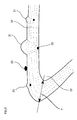
- Fig. 2 is a sectional view of an amorphous carbon coated plane 20 to show the growth of a macro-particle 21.
- Amorphous carbon 20 is applied on a cutting edge 23 of a tool.
- Graphite particles 22 float and adhere to the coated plane during the process. Round particles 21 of various diameters can be observed at the surface through an SEM. However, such particles are not desirable in the present invention. It is assumed that graphite particles 22 are present at various thickness sites of amorphous carbon 20 as shown in Fig. 2, since graphite particles 22 are scattered in the film deposition process.
- amorphous carbon film in order to improve the surface roughness of the amorphous carbon film, appropriate measures to prevent scattering of particles from the graphite material can be taken. For example, growing a film through low energy or using a filter by a magnetic field can be used.
- the surface roughness of the amorphous carbon film is desirably at least 0.002 ⁇ m and not more than 0.05 ⁇ m in Ra representation defined by the standards of JIS B0601. From the standpoint of a cutting tool, the surface roughness Ra should be as small as possible. In practice, a surface roughness Ra of zero cannot be achieved. It is found that the adhesion at the cutting edge is improved to increase the cutting performance when Ra is 0.05 ⁇ m or below as a result of various cutting experiments. Furthermore, the surface roughness is preferably at least 0.02 ⁇ m and not more than 0.5 ⁇ m in Ry representation defined by the standards of JIS BO601. If Ry exceeds 0.5 ⁇ m, any projection on the amorphous carbon film will become the adhesion origin of residuals to result in higher cutting resistance.
- the maximum film thickness of the amorphous carbon film at the cutting edge of a tool is set to 0.05 ⁇ m to 0.5 ⁇ m. If the maximum film thickness is less than 0.05 ⁇ m, the wear resistance is degraded. If the maximum film thickness exceeds 0.5 ⁇ m, the internal stress accumulated at the coated film will be increased to facilitate delamination, or cause chipping of the coated film. By setting the film thickness to not more than 0.5 ⁇ m, the size and density of the macro-particles at the surface can be reduced. There is the advantage that the surface roughness can be suppressed to not more than 0.05 ⁇ m in Ra representation and not more than 0.5 ⁇ m in Ry representation.
- the amorphous carbon film is thicker at the cutting edge of the tool as indicated by T in Fig. 2.
- the performance is improved by reducing this thickness.
- the maximum thickness T at the cutting edge of the amorphous carbon film corresponding to cutting is preferably at least 0.05 ⁇ m and not more than 0.25 ⁇ m from the standpoint of lower adhesion.
- the Knoop hardness of the amorphous carbon film is preferably at least 20 GPa and not more than 50 GPa. If the hardness is lower than 20 GPa, the wear resistance is degraded. If the hardness exceeds 50 GPa, the chipping resistance at the cutting edge is reduced. Further preferably, the Knoop hardness of the amorphous carbon film is at least 25 GPa and not more than 40 GPa.
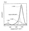
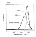
- Fig. 3 represents the Raman spectrum of the amorphous carbon of the present invention whereas Fig. 4 represents the Raman spectrum of conventional amorphous carbon that includes hydrogen.
- Fig. 4 represents the Raman spectrum of conventional amorphous carbon that includes hydrogen.
- FIG. 3 shows the peak separation result carried out in a manner similar to that described above. It is appreciated that the height of the peak of I1340 is lower than that of Fig. 3. The height of the peak in the vicinity of 700 cm -1 is indicated by I700. Similarly, the value corresponding to integration of respective peaks is represented as, for example, S700.
- the total of three peaks are observed in the amorphous carbon film of the tool of the present invention, i.e. between wave number 400 cm -1 to 1000 cm -1 , in the vicinity of 1340 cm -1 , and in the vicinity of 1560 cm -1 .
- no peak is observed at the lower wave number side of 400 cm -1 to 1000 cm -1 in the conventional coated film containing hydrogen.
- the wear resistance is improved. It is possible that the film hardness is improved by the small-size sp 2 bond and the increase of sp 3 bond with distortion.
- the intensity ratio (S700/S1340) of the integrated intensity of the peak located in the range between 400 cm -1 to 1000 cm -1 in wave number (S700) to the integrated intensity of the peak located in the vicinity of 1340 cm -1 (S1340) is preferably at least 0.01 and not more than 2.5. If the peak intensity ratio is less than 0.01, the wear resistance is equal to that of the conventional coated film. Although various film deposition experiments were carried out, a peak intensity ratio exceeding 2.5 could not be obtained by the experiments carried out, as will be described afterwards.
- the intensity ratio (I1340/I1560) of the peak intensity located in the vicinity of 1560 cm -1 (I1560) to the peak intensity located in the vicinity of 1340 cm -1 (I1340) is at least 0.1 and not more than 1.2, high wear resistance is exhibited.
- the ratio of the intensity (I1560) of the peak located in the vicinity of 1560 cm -1 to the intensity (S1340) of the peak located in the vicinity of 1340 cm -1 is also referred to as sp 2 /sp 3 , representing the presence of the carbon bond status in the coated film.
- the hardness is increased when the intensity of the peak located in the vicinity of 1560 cm -1 is high. In other words, the wear resistance is improved when the sp 3 bond characteristic is stronger.
- the intensity ratio (S1340/S1560) of the integrated intensity of the peak located in the vicinity of 1560 cm -1 (S1560) to the integrated intensity of the peak located in the vicinity of 1340 cm -1 (S1340) is to be at least 0.3 and not more than 3.
- the peak located in the vicinity of 1560 cm -1 is present in a range of at least 1560 cm -1 and not more than 1580 cm -1 , high wear resistance can be realized.
- the peak position in the Raman spectrum is affected by the stress in the coated film. In general, the peak in the Raman spectrum shifts to the higher wave number side when the stress in the coated film is high at the compressive side. In contrast, the peak in the Raman spectrum shifts to the lower wave number side when the stress in the coated film is high at the extension side. It was found that the wear resistance is improved when the stress in the coated film is high at the compressive side.
- the amorphous carbon film coated in conventional art is opaque in the visible region and has the color of brown to black.
- the amorphous carbon film of the tool of the present invention is transparent in the visible region, and exhibits interference color.
- Exhibiting interference color implies that sp 3 bond component in the amorphous carbon film is extremely great, and physical properties such as the refractive index, the optical bandgap and elastic modulus are closer to those of diamond than of the conventional amorphous carbon film.
- the amorphous carbon film of the present invention is used for the tool, superior wear resistance and heat resistance are exhibited due to the high film hardness. Since the WC base cemented carbide which is the base material of the tool of the present invention is silver or gray close to silver in color, the tool of the present invention is characterized in the appearance of exhibiting interference color.
- the interference color of the amorphous carbon film changes from (1) brown ⁇ (2) magenta ⁇ (3) violet ⁇ (4) blue-violet ⁇ (5) blue ⁇ (6) silver ⁇ (7) yellow ⁇ (8) red ⁇ (9) blue ⁇ (10) green ⁇ (11) yellow ⁇ (12) red, and then repeats the change from (8) red to (12) red thereafter, as a function of thicker film.
- the change of these colors is continuous with respect to difference in the film thickness. When the film is of a thickness intermediate therebetween, the color exhibited is the intermediate color therebetween.
- the inventors of the present invention studied the results and found that the coated film exhibited the colors between (2) magenta to (10) green when the range of 0.05 ⁇ m to 0.5 ⁇ m is selected for the maximum film thickness at the cutting edge of the tool.
- the color of the coated film may be the rainbow color corresponding to a plurality of color tones instead of a single color.
- the tool of the present invention may have a conventional amorphous carbon film of the brown to black color formed on the amorphous carbon film presenting the above-described interference colors.
- the tool of the present invention preferably has an interlayer provided between the base material and the amorphous carbon film to enhance the adherence of the amorphous carbon film.
- At least one type of element selected from the group consisting of an element from Groups IVa, Va, VIa and IIIb of the periodic table and from Group IVb of the periodic table excluding C, or carbide of at least one type of element selected from the group consisting of these elements is suitable.
- the interlayer includes at least one type of element selected from the group consisting of elements Ti, Zr, Hf, V, Nb, Ta, Cr, Mo, W and Si, or carbide of at least one type of element selected from the group consisting of these elements. Since these metal elements facilitate a strong bond with carbon, the formation of an amorphous carbon film on the interlayer of these metal elements or metal carbide produces stronger adherence.
- the thickness of the interlayer is at least 0.5 nm and less than 10 nm. Is the film thickness is thinner than this range, the interlayer cannot play its role. If the thickness exceeds this range, adherence of only a level equal to that of conventional art can be obtained. By forming such an extremely thin interlayer, significant adherence not achieved in prior art can be obtained. Thus, the lifetime of the tool can be extremely improved.
- Adhesion can further be improved by providing a mixed composition layer whose composition of each coated film is mixed or a gradient composition layer whose composition is continuously varied between the interlayer and the amorphous carbon film.
- the mixed composition layer and the gradient composition layer are not necessarily distinguishable.
- the fabrication conditions are switched from those of forming an interlayer to those for forming an amorphous carbon film, mixture occurs of the compositions of the interlayer and the amorphous carbon layer, whereby a mixed composition layer or gradient composition layer is formed.
- XPS X-ray Photo-electronic Spectroscopy
- AES Alger Electron Spectroscopy
- the amorphous carbon coated tool of the present invention is particularly suitable for working on aluminum and alloy thereof by virtue of the wear resistance and adhesion resistance.
- the tool of the present invention is most suitable to be used on non-ferrous material such as titanium, magnesium and copper.
- the tool of the present invention is also effective for cutting materials including hard particles such as graphite, organic material, and working on printed circuit boards and bi-metallic cutting of iron type material and aluminum.
- the tool of the present invention can be used in working on steel such as stainless steel and cast metal in addition to non-ferrous material by virtue of the high hardness of the amorphous carbon film.
- the amorphous carbon coated tool of the present invention can be used in an application including one type selected from the group consisting of a drill, an end mill, an indexable insert for end mill working, an indexable insert for a milling cutter, an indexable insert for a turning tool, a metal saw, a gear cutter, a reamer and a tap.
- a ⁇ 8 mm drill made of WC base cemented carbide was prepared.
- This base includes 1% by mass of (Ta, Nb) C, and Co of a content indicated in Table 1 that will be described afterwards.
- the surface of this base was subjected to the well-known cathode arc ion plating method, whereby Samples 1-38 of amorphous carbon coated drills of the present invention shown in Table 1- Table 4 were prepared.
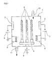
- a plurality of targets 2 and 3 are disposed in a film deposition apparatus 1.
- a drill formed of cemented carbide is attached to a base holder 4 that rotates between targets about the center point of respective targets.
- Power supplies 7 and 8 are adjusted to alter the discharging current of the cathode to coat amorphous carbon while controlling the vaporization of the target material.
- the vacuum level in deposition apparatus 1 was set to an atmosphere of 2 ⁇ 10 -3 Pa while heating up to 100°C using a base heater 6.
- Argon gas is then introduced.
- a voltage of - 1000V is applied to base holder 4 through a bias power supply 9 while maintaining the atmosphere at 2 ⁇ 10 -1 Pa.
- the argon gas is discharged.
- the gas is introduced into deposition apparatus 1 through an inlet 10 and output through an outlet 11.
- the voltage from the bias power supply 9 was set to - several hundred V.
- the temperature of the base material was set up in 100°C.
- a target selected from the group consisting of an element from Groups IVa, Va, VIa and IIIb of the periodic table and an element of Group IVb of the periodic table excluding C was vaporized and ionized, with or without hydrocarbon gas introduced, and a voltage of - several hundred V was applied to base holder 4 by bias power supply 9.
- a voltage of - several hundred V was applied to base holder 4 by bias power supply 9.
- an interlayer of this metal or of metal carbide was formed.
- the formation of an amorphous carbon film from an interlayer was effected by switching the target and atmosphere. At the time of this switching, slight mixture of the components of both layers generally occurs. It is therefore presumed that a mixed composition layer or gradient composition layer of the source material is present between the layers.
- Comparative Example 4 was deposited an amorphous carbon film at the surface of a cemented carbide drill identical to that described above using a general plasma CVD.
- composition of A5052 in Table 7 is defined in the standards of JIS H4000.
- the surface of a ⁇ 4 mm reamer made of cemented carbide was coated with an amorphous carbon film (film of Sample 2).
- the cemented carbide base of Example 2 includes 1% by mass of (Ta, Nb) C, and 7% by mass of Co.
- the hydrogen content in the amorphous carbon film is not more than 5 atomic %.
- a hydrogenated amorphous carbon film by CVD (Comparative Example 4)
- a TiN film Comparative Example 5
- a TiAlN film Comparative Example 6
- composition of ADC12 in Table 8 is defined in the standards of JIS H5302.
- the surface of a ⁇ 7 mm end mill made of cemented carbide was coated with an amorphous carbon film (film of Sample 3 of the present invention), fabricated by a method identical to that of Example 1.
- the cemented carbide base contains 1% by mass of (Ta, Nb) C and 7% by mass of Co.
- the hydrogen content in the amorphous carbon film is not more than 5 atomic %.
- a hydrogenated amorphous carbon film by CVD (Comparative Example 4), a TiN film (Comparative Example 5), and a TiAlN film (Comparative Example 6) were deposited.
- composition of ADC12 in Table 9 is defined in the standards of JIS H5302.
- the hydrogenated amorphous carbon film by CVD (Comparative Example 4) and the metal nitride films formed by PVD (Comparative Examples 5 and 6) exhibited deviation from the tolerance in surface roughness at 20m, 5m and 6m, respectively. Therefore, determination was made that the lifetime of these tools has expired. Aluminum adhering to the leading edges of the surface coated end mills that had expired lifetime was removed and studied. It was found that the coated film is no longer present, and the WC base cemented carbide of the base was exposed.
- the back side of an indexable insert was coated with an amorphous carbon film (coated film of Sample 2 of present invention) according to a method identical to that of EXAMPLE 1.
- the cemented base included 1% by mass of (Ta, Nb) C and 6% by mass of Co.
- the hydrogen content in the amorphous carbon film was not more than 5 atomic %.
- a hydrogenated amorphous carbon film by CVD (Comparative Example 4), TiN film (Comparative Example 5) and TiAlN film (Comparative Example 6) were coated.
- Each of the surface coated indexable insert 1 fabricated by the above-described method was attached to a holder having a tool diameter of 32 mm and used for an end mill process on an aluminium die cast (A390) under the conditions shown in Table 10.
- Ad axial depth of cut
- Rd radial depth of cut
- A390 in Table 10 has the composition of Al-16 ⁇ 18% (m/m) Si.
- the surface roughness of the hydrogen amorphous carbon film by CVD (Comparative Example 4), and the metal nitride film formed by PVD (Comparative Examples 5 and 6) deviated from the surface roughness tolerance at 15m, 4m and 2m, respectively. Accordingly, determination was made that the lifetime of the tools has expired. Aluminum adhering to the tip of the surface coated insert determined as having expired lifetime was removed and examined. It was found that the coated film is no longer present and the WC base cemented carbide of the base was exposed.
- the end mill of Sample 2 of the present invention exhibited deviation in the surface roughness tolerance of the workpiece when cutting has been effected for 900m. Accordingly, determination was made that the lifetime of that tool has expired when the length of 900m has been cut.
- the tool of the present invention maintains wear resistance and exhibits superior adhesion resistance.
- the cutting and wear resistance of the tool of the present invention can be greatly increased.
- an amorphous carbon film absent of hydrogen the wear resistance and adhesion resistance can further be improved.
Landscapes
- Chemical & Material Sciences (AREA)
- Engineering & Computer Science (AREA)
- Mechanical Engineering (AREA)
- Chemical Kinetics & Catalysis (AREA)
- Materials Engineering (AREA)
- Metallurgy (AREA)
- Organic Chemistry (AREA)
- Cutting Tools, Boring Holders, And Turrets (AREA)
- Physical Vapour Deposition (AREA)
- Drilling Tools (AREA)
Abstract
Description


| Workpiece material | A5052P |
| Cutting speed | 100 m/min |
| Feed | 0.5 mm/rev |
| Depth | 40 mm |
| Number of worked holes | 1000 holes |
| Workpiece material | ADC12 |
| Cutting speed | 230 m/min |
| Feed | 0.15 mm/rev |
| Depth | 15 mm |
| Workpiece material | ADC12 |
| Cutting speed | 300 m/min |
| Feed | 0.1 mm/rev |
| Depth of cut | Ad= Rd = 5 mm |
| Workpiece material | A390 |
| Cutting speed | 200 m/min |
| Feed | 0.1 mm/rev |
| Depth of cut | Ad= Rd = 3 mm |
Claims (27)
- A tool comprising a base material of WC base cemented carbide, and an amorphous carbon film covering at least a cutting edge on said base material, characterized in that:said base material has a cobalt content of not more than 12% by mass,hydrogen in said amorphous carbon film is not more than 5 atomic %, anda maximum thickness of said amorphous carbon film at the cutting edge is at least 0.05 µm and not more than 0.5 µm.
- A tool comprising a base material of WC base cemented carbide, and an amorphous carbon film covering at least a cutting edge on said base material, characterized in that:said base material has a cobalt content of not more than 12% by mass,said amorphous carbon film is formed with graphite as a source material by physical vapor deposition under an atmosphere substantially absent of hydrogen, anda maximum thickness of said amorphous carbon film at the cutting edge is at least 0.05 µm and not more than 0.5 µm.
- The amorphous carbon coated tool according to claim 1 or 2, wherein said amorphous carbon film is formed of substantially only carbon.
- The amorphous carbon coated tool according to any of claim 1-3, wherein a density of macro-particles present at a surface of said amorphous carbon film is not more than 3 × 10⁵ particles/mm2.
- The amorphous carbon coated tool according to any of claims 1-4, wherein the maximum thickness of said amorphous carbon film at a cutting edge corresponding to cutting is at least 0.05 µm and not more than 0.25 µm.
- The amorphous carbon coated tool according to any of claims 1-5, wherein said base material has a cobalt content of at least 3% by mass and not more than 7% by mass.
- The amorphous carbon coated tool according to any of claims 1-6, wherein an average crystal grain size of tungsten carbide after said base material is sintered is at least 0.1 µm and not more than 3 µm.
- The amorphous carbon coated tool according to any of claims 1-7, wherein, in said base material, at least 0.01% by mass and not more than 3% by mass is included of a compound comprising at least one type of element selected from the group consisting of a metal element from Groups IVa, Va and VIa of the periodic table, and at least one type of element selected from the group consisting of carbon and nitride.
- The amorphous carbon coated tool according to any of claims 1-8, wherein a surface roughness Ra of said amorphous carbon film is at least 0.002 µm and not more than 0.05 µm.
- The amorphous carbon coated tool according to any of claims 1-9, wherein a surface roughness Ry of said amorphous carbon film is at least 0.02 µm and not more than 0.5 µm.
- The amorphous carbon coated tool according to any of claims 1-10, wherein a Knoop hardness of said amorphous carbon film is at least 20 GPa and not more than 50 GPa.
- The amorphous carbon coated tool according to any of claims 1-11, wherein said amorphous carbon film has a peak in a range of a wave number of at least 400 cm-1 and not more than 1000 cm-1 in a Raman spectrum obtained by Raman spectroscopic analysis using an argon ion laser of 514.5 nm in wavelength.
- The amorphous carbon coated tool according to claim 12, wherein an intensity ratio (I700/I1340) of the intensity of a peak located in a range of at least 400 cm-1 and not more than 1000 cm-1 in wave number (I700) to the intensity of a peak located in a neighborhood of 1340 cm-1 (I1340) is at least 0.02 and not more than 2.5.
- The amorphous carbon coated tool according to claim 12 or 13, wherein an intensity ratio (S700/S1340) of an integrated intensity of a peak located in a range of at least 400 cm-1 and not more than 1000 cm-1 in wave number (S700) to the integrated intensity of a peak located in a neighborhood of 1340 cm-1 (S1340) is at least 0.01 and not more than 2.5.
- The amorphous carbon coated tool according to any of claims 12-14, wherein an intensity ratio (I1340/I1560) of the intensity of a peak located in a neighborhood of 1560 cm-1 (I1560) to the intensity of a peak located in a neighborhood of 1340 cm-1 (I1340) is at least 0.1 and not more than 1.2.
- The amorphous carbon coated tool according to any of claims 12-15, wherein an intensity ratio (S1340/S1560) of an integrated intensity of a peak located in a neighborhood of 1560 cm-1 (S1560) to the integrated intensity of a peak located in a neighborhood of 1340 cm-1 (S1340) is at least 0.3 and not more than 3.
- The amorphous carbon coated tool according to any of claims 12-16, wherein a peak located in a neighborhood of 1560 cm-1 includes a peak in a range of at least 1560 cm-1 and not more than 1580 cm-1
- The amorphous carbon coated tool according to any of claims 12-17, wherein said amorphous carbon film is transparent in a visible region, and exhibits an interference color.
- The amorphous carbon coated tool according to claim 18, wherein said amorphous carbon film exhibits at least one interference color selected from the group consisting of magenta, violet, blue violet, violet, blue, silver, yellow, red, and green.
- The amorphous carbon coated tool according to any of claims 1-19, wherein a coating of said amorphous carbon is directly applied on the base material.
- The amorphous carbon coated tool according to any of claims 1-20, wherein an interlayer is present between said base material and said amorphous carbon film,said interlayer being formed of at least one type of element selected from the group consisting of an element from Groups IVa, Va, VIa and IIIb of the periodic table and an element from Group IVb excluding C, or carbide of at least one type of element selected from said element group,said interlayer having a thickness of at least 0.5 nm and less than 10 nm.
- The amorphous carbon coated tool according to claim 21, wherein said interlayer includes at least one type of element selected from the group consisting of elements Ti, Zr, Hf, V, Nb, Ta, Cr, Mo, W and Si, or carbide of at least one type of element selected from said element group.
- The amorphous carbon coated tool according to claim 21 or 22, wherein a mixed composition layer having a composition of each coated film mixed or a gradient composition layer having a composition continuously changing is present between said interlayer and said amorphous carbon film.
- The amorphous carbon coated tool according to any of claims 1-23, wherein said amorphous carbon coated tool is a tool to work on soft metal material, non-ferrous material, organic material, material including hard particles, a printed circuit board, or for bi-metallic cutting of iron type material and soft metal material.
- The amorphous carbon coated tool according to any of claims 1-24, wherein said amorphous carbon coated tool is one type of tool selected from the group consisting of a drill, a micro-drill, an end mill, an indexable insert for end mill processing, an indexable insert for milling cutting, an indexable insert for turning, a metal saw, a gear cutter, a reamer, and a tap.
- A method of fabricating an amorphous carbon coated tool, comprising the steps of:wherein a maximum thickness of the amorphous carbon film is controlled to be 0.05-0.5 µm at a cutting edge.supporting a base material of WC base cemented carbide in a vacuum vessel, andapplying a zero or negative direct-current bias to the base material, and vaporizing graphite that is a source material to form an amorphous carbon film,
- The fabrication method of an amorphous carbon coated tool according to claim 26, wherein said step of forming an amorphous carbon film is carried out by cathode arc ion plating.
Applications Claiming Priority (2)
| Application Number | Priority Date | Filing Date | Title |
|---|---|---|---|
| JP2001178832 | 2001-06-13 | ||
| JP2001178832 | 2001-06-13 |
Publications (3)
| Publication Number | Publication Date |
|---|---|
| EP1266979A2 true EP1266979A2 (en) | 2002-12-18 |
| EP1266979A3 EP1266979A3 (en) | 2004-03-31 |
| EP1266979B1 EP1266979B1 (en) | 2014-04-02 |
Family
ID=19019473
Family Applications (1)
| Application Number | Title | Priority Date | Filing Date |
|---|---|---|---|
| EP02254150.2A Expired - Lifetime EP1266979B1 (en) | 2001-06-13 | 2002-06-13 | Amorphous carbon coated tool and fabrication method thereof |
Country Status (5)
| Country | Link |
|---|---|
| US (1) | US6881475B2 (en) |
| EP (1) | EP1266979B1 (en) |
| KR (1) | KR100501860B1 (en) |
| CN (1) | CN1291809C (en) |
| IL (1) | IL150195A0 (en) |
Cited By (7)
| Publication number | Priority date | Publication date | Assignee | Title |
|---|---|---|---|---|
| WO2004076171A1 (en) | 2003-02-27 | 2004-09-10 | Kennametal Inc. | Coated carbide tap |
| EP1674597A1 (en) * | 2004-12-22 | 2006-06-28 | Sandvik Intellectual Property AB | Cutting tool insert |
| EP1930105A3 (en) * | 2004-12-22 | 2008-07-02 | Sandvik Intellectual Property AB | Tool holders for chip removing machining |
| RU2486995C2 (en) * | 2011-10-03 | 2013-07-10 | Российская Федерация, от имени которой выступает Министерство промышленности и торговли Российской Федерации (Минпромторг России) | Method of making composite cathode |
| RU2527113C1 (en) * | 2013-03-04 | 2014-08-27 | Игорь Валерьевич Белашов | Method for amorphous diamond-like coating deposition on surgical blades |
| EP2614906A4 (en) * | 2010-09-07 | 2016-05-11 | Sumitomo Elec Hardmetal Corp | Cutting tool |
| WO2017148582A1 (en) * | 2016-03-01 | 2017-09-08 | Oerlikon Surface Solutions Ag, Pfäffikon | Hydrogen-free carbon coating having zirconium adhesive layer |
Families Citing this family (45)
| Publication number | Priority date | Publication date | Assignee | Title |
|---|---|---|---|---|
| JP2003251503A (en) * | 2001-12-26 | 2003-09-09 | Sumitomo Electric Ind Ltd | Surface coated cutting tool |
| US7147413B2 (en) * | 2003-02-27 | 2006-12-12 | Kennametal Inc. | Precision cemented carbide threading tap |
| JP2005007527A (en) * | 2003-06-19 | 2005-01-13 | Osg Corp | Tap |
| DE102004041234A1 (en) * | 2004-08-26 | 2006-03-02 | Ina-Schaeffler Kg | Wear resistant coating and method of making same |
| US20090191016A1 (en) * | 2005-04-04 | 2009-07-30 | Osg Corporation | Drill |
| DE502006005651D1 (en) * | 2005-09-10 | 2010-01-28 | Ixetic Hueckeswagen Gmbh | Wear resistant coating and method of making same |
| JP4735309B2 (en) * | 2006-02-10 | 2011-07-27 | トヨタ自動車株式会社 | Cavitation erosion resistant member and method of manufacturing the same |
| JP4704950B2 (en) * | 2006-04-27 | 2011-06-22 | 株式会社神戸製鋼所 | Amorphous carbon-based hard multilayer film and hard surface member having this film on the surface |
| GB2463439B (en) * | 2007-06-26 | 2012-08-08 | Nanofilm Technologies Internat Pte Ltd | Cutting tools having plasma deposited carbon coatings |
| AU2007211901B2 (en) * | 2007-08-23 | 2010-02-18 | Sandvik Intellectual Property Ab | A reamer |
| JP5165484B2 (en) * | 2008-07-16 | 2013-03-21 | ユニタック株式会社 | Drill head manufacturing method and drill head |
| JP5222764B2 (en) * | 2009-03-24 | 2013-06-26 | 株式会社神戸製鋼所 | Multilayer coating and multilayer coating covering member |
| CN101554790B (en) * | 2009-05-18 | 2012-07-04 | 浙江大学 | Ultra-hard carbon film and preparation method thereof |
| JP5351618B2 (en) * | 2009-06-05 | 2013-11-27 | 株式会社神戸製鋼所 | Negative electrode material for lithium ion secondary battery, manufacturing method thereof, and lithium ion secondary battery |
| JP5330903B2 (en) * | 2009-06-08 | 2013-10-30 | 株式会社神戸製鋼所 | Negative electrode material for lithium ion secondary battery, manufacturing method thereof, and lithium ion secondary battery |
| JP4782222B2 (en) * | 2009-08-03 | 2011-09-28 | ユニオンツール株式会社 | Amorphous carbon film for drilling tools and drilling tools |
| CN102259206A (en) * | 2010-05-25 | 2011-11-30 | 中国砂轮企业股份有限公司 | Film-coated micro-drilling needle, method for preparing same, and method for drilling hole by using film-coated micro-drilling needle |
| JP5527415B2 (en) * | 2010-08-04 | 2014-06-18 | 株式会社タンガロイ | Coated tool |
| CN103088303A (en) * | 2013-01-17 | 2013-05-08 | 西安交通大学 | Method for preparing amorphous carbon coating on surface of screw tap for processing titanium metal |
| JP5974940B2 (en) * | 2013-03-14 | 2016-08-23 | 三菱マテリアル株式会社 | Replaceable cutting head |
| DE112014002893T5 (en) * | 2013-07-15 | 2016-03-17 | GM Global Technology Operations LLC (n. d. Ges. d. Staates Delaware) | Coated tool and method of making and using the coated tool |
| JP5716861B1 (en) * | 2013-11-29 | 2015-05-13 | 三菱マテリアル株式会社 | Diamond-coated cemented carbide cutting tool and method for manufacturing the same |
| US9139908B2 (en) * | 2013-12-12 | 2015-09-22 | The Boeing Company | Gradient thin films |
| JP6211987B2 (en) * | 2014-04-22 | 2017-10-11 | 株式会社神戸製鋼所 | Mold for hot forming of Zn-plated steel sheet |
| JP6336064B2 (en) * | 2014-06-25 | 2018-06-06 | 矢崎総業株式会社 | Electric wire with terminal |
| JP2016056435A (en) * | 2014-09-12 | 2016-04-21 | 株式会社神戸製鋼所 | Manufacturing method of hard sliding member and hard sliding member |
| JP5918326B2 (en) * | 2014-09-16 | 2016-05-18 | 株式会社リケン | Covered sliding member |
| EP3196330B1 (en) * | 2014-09-17 | 2023-07-05 | Nippon Piston Ring Co., Ltd. | Coating film and manufacturing method thereof |
| CN105598457B (en) * | 2016-02-17 | 2017-12-01 | 刘三光 | A kind of scalpel blade and preparation method thereof |
| JP6534123B2 (en) * | 2016-03-23 | 2019-06-26 | 日本アイ・ティ・エフ株式会社 | Coating film, method for producing the same and PVD apparatus |
| JP6371333B2 (en) * | 2016-05-20 | 2018-08-08 | 株式会社不二機販 | Aluminum adhesion prevention method |
| WO2018112910A1 (en) * | 2016-12-23 | 2018-06-28 | 深圳市金洲精工科技股份有限公司 | Cutter composite coating, cutter, and method for preparing cutter composite coating |
| KR102079778B1 (en) * | 2017-12-14 | 2020-02-21 | 한국생산기술연구원 | Sputtering Jig |
| CN109023365B (en) * | 2018-08-10 | 2020-05-26 | 广东省新材料研究所 | Lip-type oil seal rotating shaft wear-resistant antifriction composite coating and preparation method thereof |
| JP7227089B2 (en) * | 2019-06-28 | 2023-02-21 | 株式会社ダイヤメット | Materials used for forming cutting tools and their surface protective coatings |
| JP7108049B2 (en) * | 2019-07-03 | 2022-07-27 | 日本特殊陶業株式会社 | kitchen knife and blade |
| EP4004251A1 (en) * | 2019-07-31 | 2022-06-01 | Oerlikon Surface Solutions AG, Pfäffikon | Graded hydrogen-free carbon-based hard material layer coated onto a substrate |
| JP7032579B1 (en) | 2020-04-24 | 2022-03-08 | 住友電工ハードメタル株式会社 | Cutting tools |
| JP7023388B1 (en) | 2020-04-24 | 2022-02-21 | 住友電工ハードメタル株式会社 | Cutting tools |
| EP4091745B1 (en) * | 2020-04-24 | 2024-07-10 | Sumitomo Electric Hardmetal Corp. | Cutting tool |
| CN111850484B (en) * | 2020-07-24 | 2022-05-17 | 太原理工大学 | A device and method for preparing toughened amorphous carbon-based multiphase hybrid film |
| WO2022254611A1 (en) * | 2021-06-02 | 2022-12-08 | 住友電工ハードメタル株式会社 | Cutting tool |
| CN113996825B (en) * | 2021-12-08 | 2023-08-29 | 广东工业大学 | Multi-cutting-edge tool and amorphous alloy efficient cutting method |
| JP2025523779A (en) | 2022-07-06 | 2025-07-25 | エリコン サーフェース ソリューションズ アーゲー, ファフィコン | Metal-free coating containing tetrahedral hydrogen-free amorphous carbon |
| TWI895774B (en) * | 2023-08-02 | 2025-09-01 | 尖點科技股份有限公司 | Drill bit surface modification structure and processing method thereof |
Family Cites Families (24)
| Publication number | Priority date | Publication date | Assignee | Title |
|---|---|---|---|---|
| DE3706340A1 (en) * | 1987-02-27 | 1988-09-08 | Winter & Sohn Ernst | METHOD FOR APPLYING A WEAR PROTECTIVE LAYER AND PRODUCT PRODUCED THEREOF |
| JP2666338B2 (en) | 1988-03-31 | 1997-10-22 | 三菱マテリアル株式会社 | Tungsten carbide based cemented carbide end mill |
| CA2065581C (en) * | 1991-04-22 | 2002-03-12 | Andal Corp. | Plasma enhancement apparatus and method for physical vapor deposition |
| JPH06145975A (en) * | 1992-03-20 | 1994-05-27 | Komag Inc | Method of spattering carbon film and its product |
| JPH06111287A (en) * | 1992-09-30 | 1994-04-22 | Matsushita Electric Ind Co Ltd | Magnetic recording medium |
| JP3452615B2 (en) * | 1992-10-26 | 2003-09-29 | 三菱マテリアル神戸ツールズ株式会社 | Cemented carbide, hard carbon film coated cemented carbide, method for producing cemented carbide, and tool using these alloys |
| US5474816A (en) * | 1993-04-16 | 1995-12-12 | The Regents Of The University Of California | Fabrication of amorphous diamond films |
| JP3309507B2 (en) | 1993-06-30 | 2002-07-29 | 三菱マテリアル株式会社 | Cutting tools made of surface-coated cubic boron nitride-based ceramics with a hard coating layer with excellent adhesion |
| JPH0785465A (en) | 1993-09-20 | 1995-03-31 | Tosoh Corp | Magnetic disk manufacturing method |
| US5567512A (en) * | 1993-10-08 | 1996-10-22 | Hmt Technology Corporation | Thin carbon overcoat and method of its making |
| US5482602A (en) * | 1993-11-04 | 1996-01-09 | United Technologies Corporation | Broad-beam ion deposition coating methods for depositing diamond-like-carbon coatings on dynamic surfaces |
| JPH07192254A (en) | 1993-12-28 | 1995-07-28 | Hitachi Ltd | Magnetic disk and manufacturing method thereof |
| JP3866305B2 (en) | 1994-10-27 | 2007-01-10 | 住友電工ハードメタル株式会社 | Composite high hardness material for tools |
| DE19502568C1 (en) * | 1995-01-27 | 1996-07-25 | Fraunhofer Ges Forschung | Hard, amorphous, hydrogen-free C-layers and process for their production |
| JPH09314405A (en) | 1996-05-31 | 1997-12-09 | Kyocera Corp | Coated cutting tool |
| US6110329A (en) | 1996-06-25 | 2000-08-29 | Forschungszentrum Karlsruhe Gmbh | Method of manufacturing a composite material |
| JP3026425B2 (en) | 1996-07-12 | 2000-03-27 | 治 高井 | Method for producing hard thin film and hard thin film |
| JP3512597B2 (en) | 1997-06-30 | 2004-03-29 | 京セラ株式会社 | Decorative material |
| JPH1149506A (en) * | 1997-07-31 | 1999-02-23 | Kyocera Corp | Decorative material |
| JPH1186275A (en) * | 1997-09-12 | 1999-03-30 | Sony Corp | Magnetic recording media |
| US6726993B2 (en) * | 1997-12-02 | 2004-04-27 | Teer Coatings Limited | Carbon coatings, method and apparatus for applying them, and articles bearing such coatings |
| JP3372493B2 (en) | 1998-12-09 | 2003-02-04 | 株式会社不二越 | Tool member having hard carbon-based coating |
| EP2000560B1 (en) | 1999-07-08 | 2013-10-02 | Sumitomo Electric Industries, Ltd | Hard coating and coated member |
| JP2001062605A (en) | 1999-08-30 | 2001-03-13 | Sumitomo Electric Ind Ltd | Amorphous carbon coated tool |
-
2002
- 2002-06-11 US US10/167,770 patent/US6881475B2/en not_active Expired - Lifetime
- 2002-06-12 KR KR10-2002-0032713A patent/KR100501860B1/en not_active Expired - Lifetime
- 2002-06-12 IL IL15019502A patent/IL150195A0/en active IP Right Grant
- 2002-06-13 EP EP02254150.2A patent/EP1266979B1/en not_active Expired - Lifetime
- 2002-06-13 CN CNB021227888A patent/CN1291809C/en not_active Expired - Lifetime
Cited By (14)
| Publication number | Priority date | Publication date | Assignee | Title |
|---|---|---|---|---|
| CN1829599B (en) * | 2003-02-27 | 2012-03-21 | 钴碳化钨硬质合金公司 | Coated carbide tap |
| US7147939B2 (en) | 2003-02-27 | 2006-12-12 | Kennametal Inc. | Coated carbide tap |
| EP1597064A4 (en) * | 2003-02-27 | 2008-06-25 | Kennametal Inc | Coated carbide tap |
| WO2004076171A1 (en) | 2003-02-27 | 2004-09-10 | Kennametal Inc. | Coated carbide tap |
| EP1930105A3 (en) * | 2004-12-22 | 2008-07-02 | Sandvik Intellectual Property AB | Tool holders for chip removing machining |
| US7964295B2 (en) | 2004-12-22 | 2011-06-21 | Sandvik Intellectual Property Ab | Coated cutting inserts |
| EP1674597A1 (en) * | 2004-12-22 | 2006-06-28 | Sandvik Intellectual Property AB | Cutting tool insert |
| EP2614906A4 (en) * | 2010-09-07 | 2016-05-11 | Sumitomo Elec Hardmetal Corp | Cutting tool |
| RU2486995C2 (en) * | 2011-10-03 | 2013-07-10 | Российская Федерация, от имени которой выступает Министерство промышленности и торговли Российской Федерации (Минпромторг России) | Method of making composite cathode |
| RU2527113C1 (en) * | 2013-03-04 | 2014-08-27 | Игорь Валерьевич Белашов | Method for amorphous diamond-like coating deposition on surgical blades |
| EP3423609A1 (en) * | 2016-03-01 | 2019-01-09 | Oerlikon Surface Solutions AG, Pfäffikon | Hydrogen-free carbon coating having zirconium adhesive layer |
| CN108884550A (en) * | 2016-03-01 | 2018-11-23 | 欧瑞康表面处理解决方案股份公司普费菲孔 | Hydrogen-free carbon coating with zirconium adhesion layer |
| WO2017148582A1 (en) * | 2016-03-01 | 2017-09-08 | Oerlikon Surface Solutions Ag, Pfäffikon | Hydrogen-free carbon coating having zirconium adhesive layer |
| US10844493B2 (en) | 2016-03-01 | 2020-11-24 | Oerlikon Surface Solutions Ag, Pfäffikon | Hydrogen-free carbon coating having zirconium adhesive layer |
Also Published As
| Publication number | Publication date |
|---|---|
| EP1266979B1 (en) | 2014-04-02 |
| IL150195A0 (en) | 2002-12-01 |
| KR100501860B1 (en) | 2005-07-20 |
| US20030049083A1 (en) | 2003-03-13 |
| CN1291809C (en) | 2006-12-27 |
| EP1266979A3 (en) | 2004-03-31 |
| KR20020094902A (en) | 2002-12-18 |
| CN1390667A (en) | 2003-01-15 |
| US6881475B2 (en) | 2005-04-19 |
Similar Documents
| Publication | Publication Date | Title |
|---|---|---|
| US6881475B2 (en) | Amorphous carbon coated tool and fabrication method thereof | |
| US6962751B2 (en) | Amorphous carbon coated tools and method of producing the same | |
| EP1710326B1 (en) | Surface-coated cutting tool | |
| US8945251B2 (en) | Cutting tool | |
| JP4018480B2 (en) | Coated hard tool | |
| KR101004277B1 (en) | Surface coated cutting tools | |
| KR101505222B1 (en) | Tool with multilayered metal oxide coating and method for producing the coated tool | |
| JP3719709B2 (en) | Amorphous carbon coated tool and method for manufacturing the same | |
| JP3718664B2 (en) | Amorphous carbon coated tool and method for manufacturing the same | |
| JP2009061540A (en) | Amorphous carbon film coated tool | |
| EP1710032B1 (en) | Cutting tool made of surface-coated super hard alloy, and method for manufacture thereof | |
| JP2005022073A (en) | Dlc coated tool | |
| JP2007515300A (en) | Wear resistant layer | |
| JP4445815B2 (en) | Surface coated cutting tool | |
| JP3719708B2 (en) | Amorphous carbon coated tool and method for manufacturing the same | |
| JP3963810B2 (en) | Amorphous carbon coated tool and manufacturing method thereof | |
| JP5035527B2 (en) | Surface coated cutting tool | |
| JP4456905B2 (en) | Surface coated cutting tool | |
| JP2003025112A (en) | Surface coated cemented carbide cutting tool excellent in surface lubricity for cutting chip | |
| JP2009061539A (en) | Amorphous carbon film coated tool | |
| JP2003025115A (en) | Surface coated cemented carbide cutting tool excellent in sliding property of cutting chip | |
| JP2002120103A (en) | Surface-coated cemented carbide cutting tool with excellent surface lubricity against chips | |
| JP2005262386A (en) | Surface coated cutting tool | |
| JP2003340603A (en) | Coated ultra-high hardness sintered body tool |
Legal Events
| Date | Code | Title | Description |
|---|---|---|---|
| PUAI | Public reference made under article 153(3) epc to a published international application that has entered the european phase |
Free format text: ORIGINAL CODE: 0009012 |
|
| AK | Designated contracting states |
Kind code of ref document: A2 Designated state(s): AT BE CH CY DE DK ES FI FR GB GR IE IT LI LU MC NL PT SE TR |
|
| AX | Request for extension of the european patent |
Free format text: AL;LT;LV;MK;RO;SI |
|
| RIN1 | Information on inventor provided before grant (corrected) |
Inventor name: IRIE, MIKI,C/O SUMITOMO ELECTRIC IND. LTD. Inventor name: MORIGUCHI, HIDEKIC/O SUMITOMO ELECTRIC IND. LTD. Inventor name: SETOYAMA, MAKOTO,C/O NIPPON ITF CO. LTD. Inventor name: TSUDA, KEIICHI,C/O SUMITOMO ELECTRIC IND. LTD. Inventor name: UTSUMI, YOSHIHARU,C/O SUMITOMO ELECTRIC IND. LTD. Inventor name: IKEGAYA, AKIHIKOC/O SUMITOMO ELECTRIC IND. LTD. Inventor name: FUKUI, HARUYO,C/O SUMITOMO ELECTRIC IND. LTD. Inventor name: OGATA, KIYOSHI,C/O NISSIN ELECTRIC CO. LTD. Inventor name: OHARA, HISANORI,C/O SUMITOMO ELECTRIC IND. LTD. Inventor name: OKAZAKI, NAOTO,C/O NISSIN ELECTRIC CO. LTD. Inventor name: OHTANI, SATOSHI,C/O NISSIN ELECTRIC CO. LTD. |
|
| PUAL | Search report despatched |
Free format text: ORIGINAL CODE: 0009013 |
|
| AK | Designated contracting states |
Kind code of ref document: A3 Designated state(s): AT BE CH CY DE DK ES FI FR GB GR IE IT LI LU MC NL PT SE TR |
|
| AX | Request for extension of the european patent |
Extension state: AL LT LV MK RO SI |
|
| RIC1 | Information provided on ipc code assigned before grant |
Ipc: 7C 23C 14/02 A Ipc: 7C 23C 14/06 B |
|
| 17P | Request for examination filed |
Effective date: 20040427 |
|
| AKX | Designation fees paid |
Designated state(s): DE SE |
|
| 17Q | First examination report despatched |
Effective date: 20091016 |
|
| REG | Reference to a national code |
Ref country code: DE Ref legal event code: R079 Ref document number: 60246142 Country of ref document: DE Free format text: PREVIOUS MAIN CLASS: C23C0014020000 Ipc: C23C0030000000 |
|
| RIC1 | Information provided on ipc code assigned before grant |
Ipc: C23C 14/02 20060101ALI20130911BHEP Ipc: C23C 14/06 20060101ALI20130911BHEP Ipc: C23C 30/00 20060101AFI20130911BHEP |
|
| GRAP | Despatch of communication of intention to grant a patent |
Free format text: ORIGINAL CODE: EPIDOSNIGR1 |
|
| INTG | Intention to grant announced |
Effective date: 20131030 |
|
| GRAS | Grant fee paid |
Free format text: ORIGINAL CODE: EPIDOSNIGR3 |
|
| GRAA | (expected) grant |
Free format text: ORIGINAL CODE: 0009210 |
|
| AK | Designated contracting states |
Kind code of ref document: B1 Designated state(s): DE SE |
|
| REG | Reference to a national code |
Ref country code: DE Ref legal event code: R096 Ref document number: 60246142 Country of ref document: DE Effective date: 20140515 |
|
| REG | Reference to a national code |
Ref country code: SE Ref legal event code: TRGR |
|
| RAP2 | Party data changed (patent owner data changed or rights of a patent transferred) |
Owner name: SUMITOMO ELECTRIC HARDMETAL CORP. Owner name: NISSIN ELECTRIC COMPANY, LIMITED |
|
| REG | Reference to a national code |
Ref country code: DE Ref legal event code: R081 Ref document number: 60246142 Country of ref document: DE Owner name: SUMITOMO ELECTRIC HARDMETAL CORP., ITAMI-SHI, JP Free format text: FORMER OWNER: NISSIN ELECTRIC CO., LTD., SUMITOMO ELECTRIC INDUSTRIES, L, , JP Effective date: 20140618 Ref country code: DE Ref legal event code: R081 Ref document number: 60246142 Country of ref document: DE Owner name: NISSIN ELECTRIC CO., LTD., KYOTO-SHI, JP Free format text: FORMER OWNER: NISSIN ELECTRIC CO., LTD., SUMITOMO ELECTRIC INDUSTRIES, L, , JP Effective date: 20140403 Ref country code: DE Ref legal event code: R081 Ref document number: 60246142 Country of ref document: DE Owner name: SUMITOMO ELECTRIC HARDMETAL CORP., ITAMI-SHI, JP Free format text: FORMER OWNER: NISSIN ELECTRIC CO., LTD., SUMITOMO ELECTRIC INDUSTRIES, L, , JP Effective date: 20140403 Ref country code: DE Ref legal event code: R081 Ref document number: 60246142 Country of ref document: DE Owner name: NISSIN ELECTRIC CO., LTD., KYOTO-SHI, JP Free format text: FORMER OWNER: NISSIN ELECTRIC CO., LTD., SUMITOMO ELECTRIC INDUSTRIES, L, , JP Effective date: 20140618 Ref country code: DE Ref legal event code: R081 Ref document number: 60246142 Country of ref document: DE Owner name: SUMITOMO ELECTRIC HARDMETAL CORP., ITAMI-SHI, JP Free format text: FORMER OWNERS: NISSIN ELECTRIC CO., LTD., KYOTO, JP; SUMITOMO ELECTRIC INDUSTRIES, LTD., OSAKA-SHI, OSAKA, JP Effective date: 20140403 Ref country code: DE Ref legal event code: R081 Ref document number: 60246142 Country of ref document: DE Owner name: SUMITOMO ELECTRIC HARDMETAL CORP., ITAMI-SHI, JP Free format text: FORMER OWNERS: NISSIN ELECTRIC CO., LTD., KYOTO-SHI, KYOTO, JP; SUMITOMO ELECTRIC INDUSTRIES, LTD., OSAKA-SHI, OSAKA, JP Effective date: 20140618 Ref country code: DE Ref legal event code: R081 Ref document number: 60246142 Country of ref document: DE Owner name: NISSIN ELECTRIC CO., LTD., KYOTO-SHI, JP Free format text: FORMER OWNERS: NISSIN ELECTRIC CO., LTD., KYOTO, JP; SUMITOMO ELECTRIC INDUSTRIES, LTD., OSAKA-SHI, OSAKA, JP Effective date: 20140403 Ref country code: DE Ref legal event code: R081 Ref document number: 60246142 Country of ref document: DE Owner name: NISSIN ELECTRIC CO., LTD., KYOTO-SHI, JP Free format text: FORMER OWNERS: NISSIN ELECTRIC CO., LTD., KYOTO-SHI, KYOTO, JP; SUMITOMO ELECTRIC INDUSTRIES, LTD., OSAKA-SHI, OSAKA, JP Effective date: 20140618 Ref country code: DE Ref legal event code: R081 Ref document number: 60246142 Country of ref document: DE Owner name: NISSIN ELECTRIC CO., LTD., KYOTO-SHI, JP Free format text: FORMER OWNERS: NISSIN ELECTRIC CO., LTD., KYOTO, JP; SUMITOMO ELECTRIC INDUSTRIES, LTD., OSAKA, JP Effective date: 20140403 Ref country code: DE Ref legal event code: R081 Ref document number: 60246142 Country of ref document: DE Owner name: SUMITOMO ELECTRIC HARDMETAL CORP., ITAMI-SHI, JP Free format text: FORMER OWNERS: NISSIN ELECTRIC CO., LTD., KYOTO, JP; SUMITOMO ELECTRIC INDUSTRIES, LTD., OSAKA, JP Effective date: 20140403 Ref country code: DE Ref legal event code: R081 Ref document number: 60246142 Country of ref document: DE Owner name: SUMITOMO ELECTRIC HARDMETAL CORP., ITAMI-SHI, JP Free format text: FORMER OWNERS: NISSIN ELECTRIC CO., LTD., KYOTO-SHI, KYOTO, JP; SUMITOMO ELECTRIC INDUSTRIES, LTD., OSAKA, JP Effective date: 20140618 Ref country code: DE Ref legal event code: R081 Ref document number: 60246142 Country of ref document: DE Owner name: NISSIN ELECTRIC CO., LTD., KYOTO-SHI, JP Free format text: FORMER OWNERS: NISSIN ELECTRIC CO., LTD., KYOTO-SHI, KYOTO, JP; SUMITOMO ELECTRIC INDUSTRIES, LTD., OSAKA, JP Effective date: 20140618 |
|
| REG | Reference to a national code |
Ref country code: SE Ref legal event code: RPOT |
|
| REG | Reference to a national code |
Ref country code: DE Ref legal event code: R097 Ref document number: 60246142 Country of ref document: DE |
|
| PLBE | No opposition filed within time limit |
Free format text: ORIGINAL CODE: 0009261 |
|
| STAA | Information on the status of an ep patent application or granted ep patent |
Free format text: STATUS: NO OPPOSITION FILED WITHIN TIME LIMIT |
|
| 26N | No opposition filed |
Effective date: 20150106 |
|
| REG | Reference to a national code |
Ref country code: DE Ref legal event code: R097 Ref document number: 60246142 Country of ref document: DE Effective date: 20150106 |
|
| PGFP | Annual fee paid to national office [announced via postgrant information from national office to epo] |
Ref country code: DE Payment date: 20210518 Year of fee payment: 20 |
|
| PGFP | Annual fee paid to national office [announced via postgrant information from national office to epo] |
Ref country code: SE Payment date: 20210610 Year of fee payment: 20 |
|
| REG | Reference to a national code |
Ref country code: DE Ref legal event code: R071 Ref document number: 60246142 Country of ref document: DE |
|
| REG | Reference to a national code |
Ref country code: SE Ref legal event code: EUG |