EP1266818A2 - Front end structure of a vehicle - Google Patents
Front end structure of a vehicle Download PDFInfo
- Publication number
- EP1266818A2 EP1266818A2 EP02013458A EP02013458A EP1266818A2 EP 1266818 A2 EP1266818 A2 EP 1266818A2 EP 02013458 A EP02013458 A EP 02013458A EP 02013458 A EP02013458 A EP 02013458A EP 1266818 A2 EP1266818 A2 EP 1266818A2
- Authority
- EP
- European Patent Office
- Prior art keywords
- vehicle body
- carrier
- frame
- fitting
- vehicle
- Prior art date
- Legal status (The legal status is an assumption and is not a legal conclusion. Google has not performed a legal analysis and makes no representation as to the accuracy of the status listed.)
- Granted
Links
Images

Classifications
-
- B—PERFORMING OPERATIONS; TRANSPORTING
- B62—LAND VEHICLES FOR TRAVELLING OTHERWISE THAN ON RAILS
- B62D—MOTOR VEHICLES; TRAILERS
- B62D25/00—Superstructure or monocoque structure sub-units; Parts or details thereof not otherwise provided for
- B62D25/08—Front or rear portions
- B62D25/082—Engine compartments
- B62D25/084—Radiator supports
-
- B—PERFORMING OPERATIONS; TRANSPORTING
- B60—VEHICLES IN GENERAL
- B60R—VEHICLES, VEHICLE FITTINGS, OR VEHICLE PARTS, NOT OTHERWISE PROVIDED FOR
- B60R19/00—Wheel guards; Radiator guards, e.g. grilles; Obstruction removers; Fittings damping bouncing force in collisions
- B60R19/02—Bumpers, i.e. impact receiving or absorbing members for protecting vehicles or fending off blows from other vehicles or objects
- B60R19/04—Bumpers, i.e. impact receiving or absorbing members for protecting vehicles or fending off blows from other vehicles or objects formed from more than one section in a side-by-side arrangement
- B60R19/12—Bumpers, i.e. impact receiving or absorbing members for protecting vehicles or fending off blows from other vehicles or objects formed from more than one section in a side-by-side arrangement vertically spaced
-
- B—PERFORMING OPERATIONS; TRANSPORTING
- B60—VEHICLES IN GENERAL
- B60R—VEHICLES, VEHICLE FITTINGS, OR VEHICLE PARTS, NOT OTHERWISE PROVIDED FOR
- B60R19/00—Wheel guards; Radiator guards, e.g. grilles; Obstruction removers; Fittings damping bouncing force in collisions
- B60R19/02—Bumpers, i.e. impact receiving or absorbing members for protecting vehicles or fending off blows from other vehicles or objects
- B60R19/24—Arrangements for mounting bumpers on vehicles
-
- B—PERFORMING OPERATIONS; TRANSPORTING
- B60—VEHICLES IN GENERAL
- B60R—VEHICLES, VEHICLE FITTINGS, OR VEHICLE PARTS, NOT OTHERWISE PROVIDED FOR
- B60R19/00—Wheel guards; Radiator guards, e.g. grilles; Obstruction removers; Fittings damping bouncing force in collisions
- B60R19/02—Bumpers, i.e. impact receiving or absorbing members for protecting vehicles or fending off blows from other vehicles or objects
- B60R19/18—Bumpers, i.e. impact receiving or absorbing members for protecting vehicles or fending off blows from other vehicles or objects characterised by the cross-section; Means within the bumper to absorb impact
- B60R2019/1806—Structural beams therefor, e.g. shock-absorbing
- B60R2019/1813—Structural beams therefor, e.g. shock-absorbing made of metal
-
- B—PERFORMING OPERATIONS; TRANSPORTING
- B60—VEHICLES IN GENERAL
- B60R—VEHICLES, VEHICLE FITTINGS, OR VEHICLE PARTS, NOT OTHERWISE PROVIDED FOR
- B60R19/00—Wheel guards; Radiator guards, e.g. grilles; Obstruction removers; Fittings damping bouncing force in collisions
- B60R19/02—Bumpers, i.e. impact receiving or absorbing members for protecting vehicles or fending off blows from other vehicles or objects
- B60R19/18—Bumpers, i.e. impact receiving or absorbing members for protecting vehicles or fending off blows from other vehicles or objects characterised by the cross-section; Means within the bumper to absorb impact
- B60R2019/186—Additional energy absorbing means supported on bumber beams, e.g. cellular structures or material
- B60R2019/1873—Cellular materials
-
- B—PERFORMING OPERATIONS; TRANSPORTING
- B60—VEHICLES IN GENERAL
- B60R—VEHICLES, VEHICLE FITTINGS, OR VEHICLE PARTS, NOT OTHERWISE PROVIDED FOR
- B60R21/00—Arrangements or fittings on vehicles for protecting or preventing injuries to occupants or pedestrians in case of accidents or other traffic risks
- B60R21/34—Protecting non-occupants of a vehicle, e.g. pedestrians
Definitions
- the present invention relates to a front end structure of a vehicle, more particularly to the front end structure of a vehicle body frame equipped with a module carrier.
- a front end of the vehicle body frame is joined to and incorporated into front side members provided on right and left sides of a vehicle body and a front wheel apron by welding. Accordingly, an engine room is formed into a box shape with opening provided on top and bottom sides thereof. For this reason, in an assembly process, an operator is forced to perform the prosess in uncomfortable positions such as looking into the engine room from above or below the vehicle body.
- radiator panel constituting the front end is damaged by a light collision on a front side, it is not possible to replace just only the radiator panel because the front end is formed integrally with the vehicle body frame. As a consequence, work procedures for replacement of components are increased and the number of components for replacement is also increased, whereby too much expense is incurred upon such replacement.
- the front end panel is provided separately from the vehicle body frame and the front end panel is detached from the vehicle body frame in the assembly process so as to effectuate the assembly operations from the front of the vehicle body into an engine room.
- assembled components such as a radiator and headlamps are fitted onto the front end panel to form a modularized front end panel.
- the modularized front end panel is fixed onto the vehicle body frame by bolts or the like.
- Japanese Patent Application Laid-Open No. Hei. 7-172345 discloses a technology, in which the front end panel is fixed onto a bumper beam extending in a widthwise direction of the vehicle, and bosses protruding backward from both ends of the bumper beam are fastened to front side members with the bolts, whereby the front end panel is sandwiched and fixed between the bumper beam and a vehicle body frame.
- the front end panel is just sandwiched and fixed between front end faces of the front side members and the bumper beam. Therefore, if an impact is applied from the front to a lower end of the front end panel, a large bending moment is generated at a portion sandwiched between the front side members and the bumper beam as a pivot. Therefore, the prior art has a problem of weak strength because sufficient resistance against an impact load cannot be obtained.
- a front end structure of a vehicle including at least a part of a front end panel being modularized as separate components, in which rigidity against an impact load to be applied from a front side of a vehicle body to a lower end of the modularized part is enhanced so as to receive the impact load positively, and the front end structure being capable of protecting a leg of a pedestrian.
- an aspect of the present invention is characterized by the front end structure of the vehicle, in which a module carrier is formed with a carrier upper frame and a carrier lower frame each extending in a widthwise direction of the vehicle and a stay extending in a vertical direction to connect both side ends of the two frames, and the module carrier is fixed onto a front part of a vehicle body frame to constitute at least a part of a front end.
- the front end structure includes a first fitting face which is provided on the stay, and a second fitting face which is provided on a side closer to a rear end of the vehicle body than the first fitting face, and the both fitting faces are fixed onto the vehicle body frame.
- the first fitting face provided on the stay which constitutes the module carrier, and the second fitting face positioned closer to the rear end of the vehicle body than the first fitting face are fixed onto the vehicle body frame, whereby a lower part of the module carrier is supported on the vehicle body frame with a truss structure. Accordingly, the module carrier can receive an impact load being applied from the front of the vehicle body to the carrier lower frame.
- the present invention is characterized by a front bumper beam extending in the widthwise direction of the vehicle and being fastened to the vehicle body frame so as to sandwich the first fitting face together with the vehicle body frame.
- the front bumper beam being temporarily fitted onto the first fitting face with a temporary fastener, and a pilot pin being provided on a tip of the temporary fastener so as to be engaged into a pilot hole formed on a front portion of the vehicle body frame.
- the front bumper beam being temporarily fitted onto the first fitting face with a temporary fastener, a pilot member being formed to protrude from a front edge of the vehicle body frame, and a pilot hole to be engaged with the pilot member being formed on at least any one of the first fitting face and the front bumper beam.
- a front part of the carrier lower frame protruded further forward of the vehicle body than a front part of the carrier upper frame, an upper stage shock absorber being provided on a front face of the front bumper beam, a lower stage shock absorber being provided on a front face of the carrier lower frame, and rigidity in a longitudinal(back-to-front) direction of the lower stage shock absorber being setted higher than the rigidity of the upper stage shock absorber.
- auxiliary components of a cooling system being integrated on the module carrier.
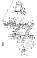
- Fig. 1 is an exploded perspective view of a front end of a vehicle
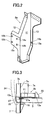
- Fig. 2 is a perspective view of a stay on a right side of a vehicle body
- Fig. 3 is a cross-sectional view taken along the line III-III in Fig 1
- Fig. 4 is a cross-sectional view taken along the line IV-IV in Fig. 1.
- Reference numeral 1 in Fig. 1 denotes a frontal vehicle body frame constituting a vehicle body frame.
- Front wheel aprons 2 are formed on both sides of the frontal vehicle body frame 1 in a widthwise direction of the vehicle so as to define both sides of an engine room.
- front side members 3 are provided on the right and the left at bottoms of the front wheel aprons 2.
- front end portions 2c including headlamp fitting portions 2b are joined to the front of the front wheel aprons 2 on the right and the left sides.
- An opening 4 is formed between the front end portions 2c.
- a frontal edge of the front side member 3 protrudes further forward than the front end portion 2c, and a module carrier 5, which constitutes a front end panel together with the front end portions 2c, is fitted and fixed onto the both front side members 3 so as to place at the opening 4.
- the module carrier 5 includes a carrier upper frame 6 and a carrier lower frame 7 on the top and the bottom thereof.
- the carrier upper frame 6 and the carrier lower frame 7 are joined with a pair of stays 8a and 8b disposed on both sides of the frames 6 and 7, thus constituting an integrated frame structure.
- the module carrier 5 may be also an integrally molded member using plastics or the like.
- the module carrier 5 is fitted onto the frontal vehicle body frame 1 so as to place at the opening 4 between the front end portions 2c.
- auxiliary components for a cooling system which are represented by a radiator unit 9 including a radiator and an air-conditioning condenser, a cooling fan 10 to be fixed at the back of the foregoing members, and the like, are fixed thereto in an assembled state.
- the module carrier 5 is modularized in advance.
- the stays 8a and 8b of the module carrier 5 have mutually symmetrical shapes, each of which is bent and formed into a Z-shaped cross section.
- frontal flanges 12 are formed to bend outward.
- back flanges 13 are formed behind the vertical wall surfaces 11 so as to bend inward.
- a front fitting face 12a as a first fitting face is formed on the midway of each of the frontal flanges 12.
- an upper portion of the frontal flange 12 of each of the stays 8a and 8b is formed into a tapered shape spreading downward, so that the upper portion is formed continuously to the front fitting face 12a.
- a lower portion of the frontal flange 12 extends vertically downward from the front fitting face 12a.
- a portion of the back flange 13 which is lower than a position corresponding to the front fitting face 12a is formed into a tapered shape extending downward. Therefore, regarding the vertical wall surface 11, a second width W2 between the front fitting face 12a and a back fitting face 13a is formed wider than a first width W1 of a lower part of the vertical wall surface 11.
- the back flange 13 positioned on the back of the front fitting face 12a constitutes the back fitting face 13a as a second fitting face, and a bolt inserting hole 13b as shown in Fig. 2 is drilled on the second fitting face 13a.
- the bolt inserting holes 12b are drilled on upper and lower outsides of the front fitting face 12a and on a lower inside thereof.
- a screw hole 12c is drilled on an upper inside thereof.
- the carrier upper frame 6 is formed to have a groove cross section and a downward opening, and upper ends of the stays 8a and 8b are fitted and joined inside the opening.
- the carrier lower frame 7 is formed to have the groove cross section and the backward opening.
- a bottom frame 7a of the carrier lower frame 7 extends further backward than an upper frame 7b thereof.
- the radiator unit 9 is mounted on the bottom frame 7a.
- a flange 7c is formed on a back end of the upper frame 7b of the carrier lower frame 7 so as to bend upward.
- hatched regions on upper ends of the stays 8a and 8b are joined to an inner surface of the carrier upper frame 6. Moreover, hatched regions on lower parts of the stays 8a and 8b are joined to the flange 7c formed on the carrier lower frame 7.
- Radiator fitting brackets 15 for fixing an upper surface of the radiator unit 9 are fixed onto a front face of the carrier upper frame 6.
- a latch fitting bracket 16 is fixed in the center of the carrier upper frame 6.
- a latch to be fixed onto the latch fitting bracket 16 and a hood striker (not shown) to be fixed onto a front end of an engine hood 17 (see Fig. 4) collectively constitute a hood locking system.
- a closed state of the engine hood is maintained by retaining the hood striker with the latch.
- member plates 18 for abutting on the front fitting face 12a are fixed on the respective front side members 3.
- screw holes 18a which correspond to the bolt-inserting holes 12b drilled on the front fitting face 12a, and a pilot hole 18b corresponding to the screw hole 12c.
- a lower end of a frame 19 with a hat-shaped cross section is fixed on each of side faces of the front side members 3 opposite to each other.
- An upper end of the frame 19- is fixed onto an opposite end of the headlamp fitting portion 2b.
- a member bracket 20 On mutually opposite faces at lower parts of the both frames 19, fixed is a member bracket 20 to abut on the second fitting faces 13a provided on the back flanges 13, which constitute the stays 8a and 8b.
- a distance between the member plate 18 fixed onto the front face of the front side member 3 and the member bracket 20 is setted to an almost equal dimension as the second width W2 of the stay 8a or 8b. Accordingly, when the module carrier 5 is placed in the opening 4, a back face of the front fitting face 12a abuts on the member plate 18 and a back face of the second fitting face 13a abuts on the member bracket 20. A weld nut 20a is fixed onto a back face of the member bracket 20 (see Fig. 4). Note that bolt-inserting holes 21 are drilled on the carrier upper frame 6 so that the carrier upper frame 6 is fastened to an upper face of the headlamp fitting portion 2b directly or via a bracket (not shown) with bolts.
- a bolt 27 with a pilot pin 27a formed integrally at its tip is passed through and screwed into the bolt-inserting hole 25a drilled on the beam bracket 25 of the front bumper beam 24, whereby a tip of the pilot pin 27a protrudes out-of the back face of the front fitting face 12a backward.
- an upper-stage shock absorber 28 and a lower-stage shock absorber 29 abut on front faces of the front bumper beam 24 and the carrier lower frame 7, respectively.
- Front sides of the shock absorbers 28 and 29 are covered with a bumper fascia 30 made of an elastic member such as plastics.
- the shock absorbers 28 and 29 are made of foamed materials having given foaming factors, such as polyurethane foam or polypropylene foam.
- the upper-stage shock absorber 28 is disposed in a position almost corresponding to a knee joint of a leg of a pedestrian (a leg impacter K for hitting test is illustrated as a model of a human leg in the drawing).
- a foaming factor and a cross-sectional area of the upper stage shock absorber 28 are setted such that the shock absorber 28 is deformed to absorb the shock applied to the knee joint when the front of the vehicle body hits the leg of the pedestrian.
- the lower stage shock absorber 29 absorbs an impact energy against rigid members such as wall faces and the vehicle, a foaming factor and a cross-sectional area of the lower stage shock absorber 29 are setted to create higher rigidity than that of the upper stage shock absorber 28 in a longitudinal direction of the vehicle body, so as to scoop up a lower leg of the pedestrian responsive to an impact.
- an impact load to be transmitted from the lower stage shock absorber 29 is received by the carrier lower frame 7 which supports the lower stage shock absorber 29. Accordingly, a front part of the carrier lower frame 7 protrudes forward so that a sufficient reactive force can be transferred to the lower stage shock absorber 29. Note that a front edge of the carrier lower frame 7 is setted at a slightly backward position from a front end of the front bumper beam 24 in this embodiment.
- radiator unit 9 including the radiator and the air-conditioning condenser are fitted onto the module carrier 5 in advance, whereby these components are modularized beforehand.
- the front bumper beam 24 is fitted temporarily to a front part of the module carrier 5. Now, procedures for temporarily fitting the front bumper beam 24 will be described in the following.
- the beam brackets 25 fixed onto both sides of the front bumper beam 24 are allowed to abut on the front fitting faces 12a formed in front of the stays 8a and 8b arranged on the both sides of the module carrier 5.
- the bolts 27 are inserted from the front side of the vehicle body into the bolt-inserting holes 25a drilled on the upper part of the inner side thereof out of the bolt-inserting holes 25a drilled on the beam bracket 25.
- the bolt 27 is screwed into the screw hole 12c drilled on the front fitting faces 12a of each of the stays 8a and 8b, and the front bumper beam 24 is thereby fitted temporarily to the module carrier 5.
- the pilot pin 27a formed on the tip of each bolt 27 protrudes backward from the back face of the second fitting face 12a.
- the vehicle body frame traveling on an assembly line has the opening 4, which is provided between the front end portions 2c. Accordingly, it is possible to perform inserting into an engine room not only from top and bottom directions of the vehicle body but also from a frontal direction thereof.
- the module carrier 5 in which the peripheral auxiliary components for the cooling system are integrated and modularized in advance, is placed at the opening 4 provided between the front end portions 2c.
- the pilot pins 27a of the bolt 27 protruding from the back faces of the second fitting faces 12a provided on the module carrier 5 are inserted into the pilot holes 18b on the member plates 18 fixed onto the front ends of the front side members 3 of the front vehicle body frame 1.
- the module carrier 5 is piloted to the space between the front end portions 2c, whereby the back faces of the front fitting faces 12a abut on the member plates 18 provided on the tips of the front side members 3, and the back faces of the second fitting faces 13a abut on the member brackets 20 fixed onto the side faces of the front side members 3.
- the respective bolt-inserting holes 25a drilled on the beam brackets 25 and the respective bolt-inserting holes 12b drilled on the front fitting faces 12a coincide with the screw holes 18a drilled on the member plates 18.
- the bolt-inserting holes 13b drilled on the second fitting faces 13a coincide with the weld nuts 20a fixed onto the member brackets 20.
- the relatively rigid front bumper beam 24 supports the bolts 27 with the pilot pin. Accordingly, if a distance between the pair of the front side members 3 is fluctuated to some extent, such fluctuation can be corrected by inserting the pilot pins 27a on the module carrier 5 into the pilot holes 18b on the front bumper beam 24.
- bolts (not shown) are inserted into three bolt-inserting holes 25a drilled on each of the beam brackets 25 except the bolt-inserting hole 25a where the bolt 27 is inserted, and into the bolt-inserting holes 12b drilled on each of the front fitting faces 12a, whereby the bolts are further screwed into the screw holes 18a provided on each of the member plates 18.
- the front fitting faces 12a of the modular carrier 5 are attached and fixed between the member plates 18 and the beam brackets 25.
- the bolts inserted into the bolt-inserting holes 13b drilled on the back fitting faces 13a are further screwed into the weld nuts 20a fixed onto the member brackets 20 in order to fix the back fitting faces 13a.
- both ends of the carrier upper frame 6 are fixed onto the front end portions 2c either directly or via brackets (not shown).
- the both shock absorbers 28 and 29 are covered with the bumper fascia 30, which constitutes a part of a shape of the vehicle body.
- an upper part and a lower part of the bumper fascia 30 are fixed onto the module carrier 5 and to the front end portions 2c to complete assembly around the front end panel.
- the lower part of the bumper fascia 30 may be allowed to extend downward under the bottom frame 7a of the carrier lower frame 7 and fixed onto the bottom frame 7a with clips or bolts.
- the leg impacter K hits the front of the vehicle body, a part of the upper stage shock absorber 28 colliding on the vicinity of the knee joint of the leg impacter K is subjected to plastic deformation, whereby the impact energy upon collision is absorbed.
- the lower stage shock absorber 29 has more rigidity than that of the upper stage shock absorber 28, which is attributable to a formation under a lower foaming factor than the upper stage shock absorber 28.
- the front end face of the carrier lower frame 7 abutting on the back face of the lower stage shock absorber 29 protrudes to the position being slightly setted back from the front end face of the front bumper beam 24. Accordingly, a thickness of the lower stage shock absorber 29 is reduced and an amount of the deformation upon receipt of the impact is thereby suppressed.
- the front end face of the carrier lower frame 7 can receive the impact load received by the lower stage shock absorber 29, and a sufficient reactive force against the leg can be generated.
- the rigidity on the lower part of the bumper fascia 30 can be enhanced by fixing the lower part to the bottom frame 7a with the clips or the bolts. Accordingly, the bumper fascia 30 can also generate some reactive force by its own rigidity.
- an upper part of the leg impacter K is inclined onto the engine hood 17 of the vehicle body owing to the deformation of the upper stage shock absorber 28, and a lower part of the leg impacter K is scooped up by the reactive force of the lower stage shock absorber 29. Accordingly, it is possible to protect the lower leg of the pedestrian from injury.
- the impact load eventually causes bending moments on the stays 8a and 8b fixing the carrier lower frame 7 on the lower ends thereof, in a counterclockwise direction according to Fig. 4 while taking the front fitting faces 12a as pivots.
- the back fitting faces 13a which are formed closer to the rear end than that of the front fitting faces 12a, are fixed onto the member brackets 20 being fixed onto the front side members 3.
- the second width W2 between the front fitting face 12a and the back fitting face 13a is formed wider than the first width W1 at the lower part of the vertical wall surface 11. Therefore, the lower parts of the stays 8a and 8b are supported by truss structures against the front side members 3, and the stays 8a and 8b can receive the impact load applied from the carrier lower frame 7 securely with an increased strength.
- the bolt 27 may be substituted by an eyebolt associated with a pilot pin. Use of such eyebolt can impart a pulling function as well. Otherwise, a screw hole may be provided on a head of the bolt 27 so as to effectively engage the eyebolt.
- the module carrier may include an entire front end panel including the headlamp fitting portions.
- pins or bolts having piloting functions may be provided on the front ends of the front side members 3 in a protruding manner, and the pilot holes for allowing insertions of the foregoing pins or bolts may be drilled on the front fitting faces 12a formed on the stays 8a and 8b constituting the module carrier 5 and on the beam brackets 25.
- the part of the front end panel is composed of the module carrier of separate components, rigidity against the impact load applied from the front side of the vehicle body to the lower end of the module carrier can be enhanced so as to receive the impact load firmly.
- the rigidity against the impact load is enhanced, the sufficient reactive force can be generated against the impact load if the front of the vehicle body hits the leg of the pedestrian. Such reactive force is effective for scooping up the leg of the pedestrian, and the leg can be thereby protected.
Landscapes
- Engineering & Computer Science (AREA)
- Mechanical Engineering (AREA)
- Chemical & Material Sciences (AREA)
- Combustion & Propulsion (AREA)
- Transportation (AREA)
- Body Structure For Vehicles (AREA)
Abstract
Description
- The present invention relates to a front end structure of a vehicle, more particularly to the front end structure of a vehicle body frame equipped with a module carrier.
- Conventionally, a front end of the vehicle body frame is joined to and incorporated into front side members provided on right and left sides of a vehicle body and a front wheel apron by welding. Accordingly, an engine room is formed into a box shape with opening provided on top and bottom sides thereof. For this reason, in an assembly process, an operator is forced to perform the prosess in uncomfortable positions such as looking into the engine room from above or below the vehicle body.
- Moreover, if a radiator panel constituting the front end is damaged by a light collision on a front side, it is not possible to replace just only the radiator panel because the front end is formed integrally with the vehicle body frame. As a consequence, work procedures for replacement of components are increased and the number of components for replacement is also increased, whereby too much expense is incurred upon such replacement. In addition, it is not possible to change the radiator panel and components related thereto, which collectively constitute the front end, into lightweight materials such as plastics. Such limitation constitutes obstacles to achieve a weight reduction or a reduction of moment of inertia.
- As countermeasures for the foregoing problems, various technologies have been disclosed in the past. According to those technologies, the front end panel is provided separately from the vehicle body frame and the front end panel is detached from the vehicle body frame in the assembly process so as to effectuate the assembly operations from the front of the vehicle body into an engine room. Moreover, assembled components such as a radiator and headlamps are fitted onto the front end panel to form a modularized front end panel. Thereafter, the modularized front end panel is fixed onto the vehicle body frame by bolts or the like.
- For example, Japanese Patent Application Laid-Open No. Hei. 7-172345 discloses a technology, in which the front end panel is fixed onto a bumper beam extending in a widthwise direction of the vehicle, and bosses protruding backward from both ends of the bumper beam are fastened to front side members with the bolts, whereby the front end panel is sandwiched and fixed between the bumper beam and a vehicle body frame.
- However, according to the prior art described above, the front end panel is just sandwiched and fixed between front end faces of the front side members and the bumper beam. Therefore, if an impact is applied from the front to a lower end of the front end panel, a large bending moment is generated at a portion sandwiched between the front side members and the bumper beam as a pivot. Therefore, the prior art has a problem of weak strength because sufficient resistance against an impact load cannot be obtained.
- Incidentally, when the strength is insufficient in the direction of the lower end of the front end panel, if a leg of a pedestrian hits a front bumper, the lower end of the front end panel tends to be inclined backward of the vehicle body due to an impact energy from the leg. If the front end panel is inclined backward of the vehicle body, both upper leg and lower limb(legs) of the pedestrian tend to be bent at a knee joint toward the vehicle body so that the lower limb is caught into a lower part of the vehicle body. Such an aspect is not preferable in terms of pedestrian protection.
- In consideration of the foregoing problems, it is an object of the present invention to provide a front end structure of a vehicle including at least a part of a front end panel being modularized as separate components, in which rigidity against an impact load to be applied from a front side of a vehicle body to a lower end of the modularized part is enhanced so as to receive the impact load positively, and the front end structure being capable of protecting a leg of a pedestrian.
- To attain the foregoing object, an aspect of the present invention is characterized by the front end structure of the vehicle, in which a module carrier is formed with a carrier upper frame and a carrier lower frame each extending in a widthwise direction of the vehicle and a stay extending in a vertical direction to connect both side ends of the two frames, and the module carrier is fixed onto a front part of a vehicle body frame to constitute at least a part of a front end. Here, the front end structure includes a first fitting face which is provided on the stay, and a second fitting face which is provided on a side closer to a rear end of the vehicle body than the first fitting face, and the both fitting faces are fixed onto the vehicle body frame.
- In this structure, the first fitting face provided on the stay which constitutes the module carrier, and the second fitting face positioned closer to the rear end of the vehicle body than the first fitting face are fixed onto the vehicle body frame, whereby a lower part of the module carrier is supported on the vehicle body frame with a truss structure. Accordingly, the module carrier can receive an impact load being applied from the front of the vehicle body to the carrier lower frame.
- In another aspect of the present invention, the present invention is characterized by a front bumper beam extending in the widthwise direction of the vehicle and being fastened to the vehicle body frame so as to sandwich the first fitting face together with the vehicle body frame.
- In still another aspect of the invention, it is characterized by the front bumper beam being temporarily fitted onto the first fitting face with a temporary fastener, and a pilot pin being provided on a tip of the temporary fastener so as to be engaged into a pilot hole formed on a front portion of the vehicle body frame.
- In still another aspect of the present invention, it is characterized by the front bumper beam being temporarily fitted onto the first fitting face with a temporary fastener, a pilot member being formed to protrude from a front edge of the vehicle body frame, and a pilot hole to be engaged with the pilot member being formed on at least any one of the first fitting face and the front bumper beam.
- In still further another aspect of the present invention, it is characterized by a front part of the carrier lower frame protruded further forward of the vehicle body than a front part of the carrier upper frame, an upper stage shock absorber being provided on a front face of the front bumper beam, a lower stage shock absorber being provided on a front face of the carrier lower frame, and rigidity in a longitudinal(back-to-front) direction of the lower stage shock absorber being setted higher than the rigidity of the upper stage shock absorber.
- In still another aspect of the present invention, it is characterized by auxiliary components of a cooling system being integrated on the module carrier.
- These and other objects and advantages of the present invention will become understood from following descriptions with reference to accompanying drawings, wherein:
- Fig. 1 is an exploded perspective view of a front end of a vehicle;
- Fig. 2 is a perspective view of a stay on a right side of a vehicle body;
- Fig. 3 is a cross-sectional view taken along the line III-III in Fig 1; and
- Fig. 4 is the cross-sectional view taken along the line IV-IV in Fig. 1.
-
- Now, an embodiment of the present invention will be described with reference to accompanying drawings. Here, Fig. 1 is an exploded perspective view of a front end of a vehicle; Fig. 2 is a perspective view of a stay on a right side of a vehicle body; Fig. 3 is a cross-sectional view taken along the line III-III in Fig 1; and Fig. 4 is a cross-sectional view taken along the line IV-IV in Fig. 1.
- Reference numeral 1 in Fig. 1 denotes a frontal vehicle body frame constituting a vehicle body frame.
Front wheel aprons 2 are formed on both sides of the frontal vehicle body frame 1 in a widthwise direction of the vehicle so as to define both sides of an engine room. Moreover,front side members 3 are provided on the right and the left at bottoms of the front wheel aprons 2. - Moreover,
front end portions 2c including headlamp fittingportions 2b are joined to the front of the front wheel aprons 2 on the right and the left sides. Anopening 4 is formed between thefront end portions 2c. A frontal edge of thefront side member 3 protrudes further forward than thefront end portion 2c, and amodule carrier 5, which constitutes a front end panel together with thefront end portions 2c, is fitted and fixed onto the bothfront side members 3 so as to place at theopening 4. - The
module carrier 5 includes a carrierupper frame 6 and a carrierlower frame 7 on the top and the bottom thereof. The carrierupper frame 6 and the carrierlower frame 7 are joined with a pair ofstays frames module carrier 5 may be also an integrally molded member using plastics or the like. - In an assembling process, the
module carrier 5 is fitted onto the frontal vehicle body frame 1 so as to place at theopening 4 between thefront end portions 2c. In an aperture formed in the center of themodule carrier 5 and in the periphery of the aperture, auxiliary components for a cooling system, which are represented by aradiator unit 9 including a radiator and an air-conditioning condenser, acooling fan 10 to be fixed at the back of the foregoing members, and the like, are fixed thereto in an assembled state. In this way, themodule carrier 5 is modularized in advance. - As shown in Fig. 2 and Fig. 3, the
stays module carrier 5 have mutually symmetrical shapes, each of which is bent and formed into a Z-shaped cross section. In front of avertical wall surfaces 11 opposite to each other,frontal flanges 12 are formed to bend outward. Moreover,back flanges 13 are formed behind thevertical wall surfaces 11 so as to bend inward. In addition, afront fitting face 12a as a first fitting face is formed on the midway of each of thefrontal flanges 12. - As shown in Fig. 4, an upper portion of the
frontal flange 12 of each of thestays face 12a. Moreover, a lower portion of thefrontal flange 12 extends vertically downward from the frontfitting face 12a. Meanwhile, a portion of theback flange 13 which is lower than a position corresponding to the front fittingface 12a is formed into a tapered shape extending downward. Therefore, regarding thevertical wall surface 11, a second width W2 between the front fittingface 12a and a back fittingface 13a is formed wider than a first width W1 of a lower part of thevertical wall surface 11. - Moreover, the
back flange 13 positioned on the back of the front fittingface 12a constitutes the back fittingface 13a as a second fitting face, and abolt inserting hole 13b as shown in Fig. 2 is drilled on the secondfitting face 13a. - Meanwhile, as shown in Figs. 1 and 2, the
bolt inserting holes 12b are drilled on upper and lower outsides of the front fittingface 12a and on a lower inside thereof. In addition, ascrew hole 12c is drilled on an upper inside thereof. - Moreover, the carrier
upper frame 6 is formed to have a groove cross section and a downward opening, and upper ends of thestays lower frame 7 is formed to have the groove cross section and the backward opening. Here, abottom frame 7a of the carrierlower frame 7 extends further backward than anupper frame 7b thereof. Theradiator unit 9 is mounted on thebottom frame 7a. In addition, aflange 7c is formed on a back end of theupper frame 7b of the carrierlower frame 7 so as to bend upward. - As shown in Fig. 2, hatched regions on upper ends of the
stays upper frame 6. Moreover, hatched regions on lower parts of thestays flange 7c formed on the carrierlower frame 7. - Radiator
fitting brackets 15 for fixing an upper surface of theradiator unit 9 are fixed onto a front face of the carrierupper frame 6. Moreover, a latchfitting bracket 16 is fixed in the center of the carrierupper frame 6. Note that a latch to be fixed onto the latchfitting bracket 16 and a hood striker (not shown) to be fixed onto a front end of an engine hood 17 (see Fig. 4) collectively constitute a hood locking system. A closed state of the engine hood is maintained by retaining the hood striker with the latch. - Moreover,
member plates 18 for abutting on the frontfitting face 12a are fixed on the respectivefront side members 3. On eachmember plate 18, drilled arescrew holes 18a, which correspond to the bolt-insertingholes 12b drilled on the frontfitting face 12a, and apilot hole 18b corresponding to thescrew hole 12c. In addition, a lower end of aframe 19 with a hat-shaped cross section is fixed on each of side faces of thefront side members 3 opposite to each other. An upper end of the frame 19-is fixed onto an opposite end of the headlampfitting portion 2b. On mutually opposite faces at lower parts of the bothframes 19, fixed is amember bracket 20 to abut on the second fitting faces 13a provided on theback flanges 13, which constitute thestays - As shown in Fig. 3, a distance between the
member plate 18 fixed onto the front face of thefront side member 3 and themember bracket 20 is setted to an almost equal dimension as the second width W2 of thestay module carrier 5 is placed in theopening 4, a back face of the frontfitting face 12a abuts on themember plate 18 and a back face of the secondfitting face 13a abuts on themember bracket 20. Aweld nut 20a is fixed onto a back face of the member bracket 20 (see Fig. 4). Note that bolt-insertingholes 21 are drilled on the carrierupper frame 6 so that the carrierupper frame 6 is fastened to an upper face of the headlampfitting portion 2b directly or via a bracket (not shown) with bolts. -
Beam brackets 25, which are provided on thefront bumper beam 24 extending in the widthwise direction of the vehicle, abut on front faces of the front fitting faces 12a. On each of thebeam brackets 25, drilled are bolt-insertingholes 25a corresponding to the bolt-insertinghole 12b and thescrew hole 12c drilled on the frontfitting face 12a. - With respect to the
screw hole 12c drilled on the frontfitting face 12a, abolt 27 with apilot pin 27a formed integrally at its tip is passed through and screwed into the bolt-insertinghole 25a drilled on thebeam bracket 25 of thefront bumper beam 24, whereby a tip of thepilot pin 27a protrudes out-of the back face of the frontfitting face 12a backward. - Moreover, as shown in Fig. 4, an upper-
stage shock absorber 28 and a lower-stage shock absorber 29 abut on front faces of thefront bumper beam 24 and the carrierlower frame 7, respectively. Front sides of theshock absorbers bumper fascia 30 made of an elastic member such as plastics. Theshock absorbers - Here, as shown in Fig. 4, the upper-
stage shock absorber 28 is disposed in a position almost corresponding to a knee joint of a leg of a pedestrian (a leg impacter K for hitting test is illustrated as a model of a human leg in the drawing). A foaming factor and a cross-sectional area of the upperstage shock absorber 28 are setted such that theshock absorber 28 is deformed to absorb the shock applied to the knee joint when the front of the vehicle body hits the leg of the pedestrian. Meanwhile, since the lowerstage shock absorber 29 absorbs an impact energy against rigid members such as wall faces and the vehicle, a foaming factor and a cross-sectional area of the lowerstage shock absorber 29 are setted to create higher rigidity than that of the upperstage shock absorber 28 in a longitudinal direction of the vehicle body, so as to scoop up a lower leg of the pedestrian responsive to an impact. - In this case, an impact load to be transmitted from the lower
stage shock absorber 29 is received by the carrierlower frame 7 which supports the lowerstage shock absorber 29. Accordingly, a front part of the carrierlower frame 7 protrudes forward so that a sufficient reactive force can be transferred to the lowerstage shock absorber 29. Note that a front edge of the carrierlower frame 7 is setted at a slightly backward position from a front end of thefront bumper beam 24 in this embodiment. - Next, a function of the embodiment of the foregoing structure will be described. Auxiliary components mainly composed of the
radiator unit 9 including the radiator and the air-conditioning condenser are fitted onto themodule carrier 5 in advance, whereby these components are modularized beforehand. - Moreover, the
front bumper beam 24 is fitted temporarily to a front part of themodule carrier 5. Now, procedures for temporarily fitting thefront bumper beam 24 will be described in the following. - First, the
beam brackets 25 fixed onto both sides of thefront bumper beam 24 are allowed to abut on the front fitting faces 12a formed in front of thestays module carrier 5. Then, thebolts 27 are inserted from the front side of the vehicle body into the bolt-insertingholes 25a drilled on the upper part of the inner side thereof out of the bolt-insertingholes 25a drilled on thebeam bracket 25. In this way, thebolt 27 is screwed into thescrew hole 12c drilled on the front fitting faces 12a of each of thestays front bumper beam 24 is thereby fitted temporarily to themodule carrier 5. In this case, thepilot pin 27a formed on the tip of eachbolt 27 protrudes backward from the back face of the secondfitting face 12a. - Meanwhile, the vehicle body frame traveling on an assembly line has the
opening 4, which is provided between thefront end portions 2c. Accordingly, it is possible to perform inserting into an engine room not only from top and bottom directions of the vehicle body but also from a frontal direction thereof. - Thereafter, when the vehicle body frame is conveyed to a processing section for installing the
module carrier 5, themodule carrier 5, in which the peripheral auxiliary components for the cooling system are integrated and modularized in advance, is placed at theopening 4 provided between thefront end portions 2c. - Upon fitting, the pilot pins 27a of the
bolt 27 protruding from the back faces of the second fitting faces 12a provided on themodule carrier 5 are inserted into thepilot holes 18b on themember plates 18 fixed onto the front ends of thefront side members 3 of the front vehicle body frame 1. - Then, the
module carrier 5 is piloted to the space between thefront end portions 2c, whereby the back faces of the front fitting faces 12a abut on themember plates 18 provided on the tips of thefront side members 3, and the back faces of the second fitting faces 13a abut on themember brackets 20 fixed onto the side faces of thefront side members 3. Then, the respective bolt-insertingholes 25a drilled on thebeam brackets 25 and the respective bolt-insertingholes 12b drilled on the front fitting faces 12a coincide with thescrew holes 18a drilled on themember plates 18. Moreover, the bolt-insertingholes 13b drilled on the second fitting faces 13a coincide with the weld nuts 20a fixed onto themember brackets 20. - Incidentally, the relatively rigid
front bumper beam 24 supports thebolts 27 with the pilot pin. Accordingly, if a distance between the pair of thefront side members 3 is fluctuated to some extent, such fluctuation can be corrected by inserting the pilot pins 27a on themodule carrier 5 into thepilot holes 18b on thefront bumper beam 24. - Subsequently, bolts (not shown) are inserted into three bolt-inserting
holes 25a drilled on each of thebeam brackets 25 except the bolt-insertinghole 25a where thebolt 27 is inserted, and into the bolt-insertingholes 12b drilled on each of the front fitting faces 12a, whereby the bolts are further screwed into thescrew holes 18a provided on each of themember plates 18. In this way, the front fitting faces 12a of themodular carrier 5 are attached and fixed between themember plates 18 and thebeam brackets 25. Moreover, the bolts inserted into the bolt-insertingholes 13b drilled on the back fitting faces 13a are further screwed into the weld nuts 20a fixed onto themember brackets 20 in order to fix the back fitting faces 13a. - Meanwhile, both ends of the carrier
upper frame 6 are fixed onto thefront end portions 2c either directly or via brackets (not shown). - Thereafter, back faces of the upper
stage shock absorber 28 and the lowerstage shock absorber 29 are fixed onto the front end face of thefront bumper beam 24 and the front end face of the carrierlower frame 7, respectively. Further, the bothshock absorbers bumper fascia 30, which constitutes a part of a shape of the vehicle body. Then, an upper part and a lower part of thebumper fascia 30 are fixed onto themodule carrier 5 and to thefront end portions 2c to complete assembly around the front end panel. In this case, the lower part of thebumper fascia 30 may be allowed to extend downward under thebottom frame 7a of the carrierlower frame 7 and fixed onto thebottom frame 7a with clips or bolts. - Next, description will be made regarding an operation of the front end of the vehicle body thus assembled in the event of hitting the leg impacter K from the front side of the vehicle body.
- When the leg impacter K hits the front of the vehicle body, a part of the upper
stage shock absorber 28 colliding on the vicinity of the knee joint of the leg impacter K is subjected to plastic deformation, whereby the impact energy upon collision is absorbed. Meanwhile, the lowerstage shock absorber 29 has more rigidity than that of the upperstage shock absorber 28, which is attributable to a formation under a lower foaming factor than the upperstage shock absorber 28. In addition, the front end face of the carrierlower frame 7 abutting on the back face of the lowerstage shock absorber 29 protrudes to the position being slightly setted back from the front end face of thefront bumper beam 24. Accordingly, a thickness of the lowerstage shock absorber 29 is reduced and an amount of the deformation upon receipt of the impact is thereby suppressed. - Therefore, the front end face of the carrier
lower frame 7 can receive the impact load received by the lowerstage shock absorber 29, and a sufficient reactive force against the leg can be generated. In this case, the rigidity on the lower part of thebumper fascia 30 can be enhanced by fixing the lower part to thebottom frame 7a with the clips or the bolts. Accordingly, thebumper fascia 30 can also generate some reactive force by its own rigidity. - As a result, as illustrated with arrows in Fig. 4, an upper part of the leg impacter K is inclined onto the
engine hood 17 of the vehicle body owing to the deformation of the upperstage shock absorber 28, and a lower part of the leg impacter K is scooped up by the reactive force of the lowerstage shock absorber 29. Accordingly, it is possible to protect the lower leg of the pedestrian from injury. - Incidentally, as shown in Fig. 4, when the impact load from the lower leg of the leg impacter K is applied to the front end of the carrier
lower frame 7, the impact load is transmitted to lower parts of thestays flange 7c formed by bending on the rear end of theupper frame 7b of the carrierlower frame 7. Then, the impact load is received by themember plates 18 fixed onto the front ends of thefront side members 3 abutting on the front fitting faces 12a, which are formed on thestays - In this stage, the impact load eventually causes bending moments on the
stays lower frame 7 on the lower ends thereof, in a counterclockwise direction according to Fig. 4 while taking the front fitting faces 12a as pivots. However, the back fitting faces 13a, which are formed closer to the rear end than that of the front fitting faces 12a, are fixed onto themember brackets 20 being fixed onto thefront side members 3. In addition, the second width W2 between the frontfitting face 12a and the backfitting face 13a is formed wider than the first width W1 at the lower part of thevertical wall surface 11. Therefore, the lower parts of thestays front side members 3, and thestays lower frame 7 securely with an increased strength. - It should be understood that the present invention is not limited to the particular embodiment as described above. For example, the
bolt 27 may be substituted by an eyebolt associated with a pilot pin. Use of such eyebolt can impart a pulling function as well. Otherwise, a screw hole may be provided on a head of thebolt 27 so as to effectively engage the eyebolt. Meanwhile, the module carrier may include an entire front end panel including the headlamp fitting portions. - Further, pins or bolts having piloting functions may be provided on the front ends of the
front side members 3 in a protruding manner, and the pilot holes for allowing insertions of the foregoing pins or bolts may be drilled on the front fitting faces 12a formed on thestays module carrier 5 and on thebeam brackets 25. - As described above, according to the present invention, if at least the part of the front end panel is composed of the module carrier of separate components, rigidity against the impact load applied from the front side of the vehicle body to the lower end of the module carrier can be enhanced so as to receive the impact load firmly.
- Moreover, since the rigidity against the impact load is enhanced, the sufficient reactive force can be generated against the impact load if the front of the vehicle body hits the leg of the pedestrian. Such reactive force is effective for scooping up the leg of the pedestrian, and the leg can be thereby protected.
Claims (6)
- A front end structure of a vehicle provided with a module carrier (5) with a carrier upper frame(6) and a carrier lower frame(7) each extending in a widthwise direction of the vehicle and a stay(8a,8b) extending in a vertical direction to connect both side ends of the two frames, the module carrier(5) being fixed onto a front part of a vehicle body frame(1) with at least a part of a front end, comprising:a first fitting face(12a) provided on the stay; anda second fitting face(13a) provided on a side closer to a rear end of a vehicle body than the first fitting face,the both fitting faces being fixed onto the vehicle body frame.
- The front end structure of the vehicle according to claim 1, further comprising:a front bumper beam(24) extending in the widthwise direction of the vehicle and fastened to the vehicle body frame so as to sandwich the first fitting face together with the vehicle body frame.
- The front end structure of the vehicle according to claim 2, wherein:the front bumper beam is temporarily fitted onto the first fitting face with a temporary fastener(27); anda pilot pin(27a) is provided on a tip of the temporary fastener so as to be engaged into a pilot hole(18b) formed on a front portion of the vehicle body frame.
- The front end structure of the vehicle according to claim 2, wherein:the front bumper beam is temporarily fitted onto the first fitting face with a temporary fastener(27);a pilot member is formed to protrude on a front edge of the vehicle body frame; andat least either one of the first fitting face(12a) or the front bumper beam(24) has a pilot hole(18b) engaged with the pilot member.
- The front end structure of the vehicle according to any one of claims 2 to 4, further comprising:wherein:an upper stage shock absorber(28) provided on a front face of the front bumper beam; anda lower stage shock absorber(29) provided on a front face of the carrier lower frame,a front part of the carrier lower frame protrudes further forward of the vehicle body than a front part of the carrier upper frame(6); anda rigidity in a longitudinal direction of the lower stage shock absorber is setted higher than one of the upper stage shock absorber.
- The front end structure of the vehicle according to any one of claims 1 to 5, wherein:components(9,10) for a cooling system are integrated on the module carrier(5).
Applications Claiming Priority (2)
| Application Number | Priority Date | Filing Date | Title |
|---|---|---|---|
| JP2001182043 | 2001-06-15 | ||
| JP2001182043A JP4762444B2 (en) | 2001-06-15 | 2001-06-15 | Vehicle front-end structure |
Publications (3)
| Publication Number | Publication Date |
|---|---|
| EP1266818A2 true EP1266818A2 (en) | 2002-12-18 |
| EP1266818A3 EP1266818A3 (en) | 2003-03-12 |
| EP1266818B1 EP1266818B1 (en) | 2006-08-09 |
Family
ID=19022211
Family Applications (1)
| Application Number | Title | Priority Date | Filing Date |
|---|---|---|---|
| EP02013458A Expired - Lifetime EP1266818B1 (en) | 2001-06-15 | 2002-06-13 | Front end structure of a vehicle |
Country Status (4)
| Country | Link |
|---|---|
| US (1) | US6672652B2 (en) |
| EP (1) | EP1266818B1 (en) |
| JP (1) | JP4762444B2 (en) |
| DE (1) | DE60213714T2 (en) |
Cited By (19)
| Publication number | Priority date | Publication date | Assignee | Title |
|---|---|---|---|---|
| FR2849422A1 (en) * | 2002-12-26 | 2004-07-02 | Renault Sa | Vehicle chassiss front part, has assembling unit linking two cross frame units to form space for air passage between frame units, and having module with screws and parallel arms for fixing frame units and rails, respectively |
| EP1527957A1 (en) * | 2003-10-28 | 2005-05-04 | Mitsubishi Fuso Truck and Bus Corporation | Impact shock absorbing structure of a vehicle |
| WO2007011238A1 (en) * | 2005-07-22 | 2007-01-25 | Norsk Hydro Asa | Crash protection system |
| EP1754650A1 (en) * | 2005-08-20 | 2007-02-21 | HBPO GmbH | Front-end module with mounting carrier with lower girder |
| EP1754652A1 (en) * | 2005-08-18 | 2007-02-21 | MAN Nutzfahrzeuge Aktiengesellschaft | Vehicle body frame for a utiliity vehicle. |
| WO2007085582A1 (en) * | 2006-01-26 | 2007-08-02 | Faurecia Kunststoffe Automobilsysteme Gmbh | Motor vehicle longitudinal beam and motor vehicle front unit |
| EP1754654A3 (en) * | 2005-08-20 | 2008-06-25 | HBPO GmbH | Flange joint for screwing a crash box and an assembly carrier to a vehicle chassis rail |
| FR2910865A1 (en) * | 2006-12-28 | 2008-07-04 | Plastic Omnium Cie | Shock-absorbing system supporting element for motor vehicle, has shock absorbers and support surface that is arranged in manner to extend surface under plate and is not irreversibly distorted when vehicle is subjected to shock assurance |
| WO2009013416A1 (en) * | 2007-07-26 | 2009-01-29 | Peugeot Citroën Automobiles SA | Method for mounting a bumper on the structure of an automobile |
| DE102004030794B4 (en) * | 2004-06-25 | 2009-05-07 | Hbpo Gmbh | Vehicle front end module with pedestrian protection device |
| EP1800960A3 (en) * | 2005-12-21 | 2009-05-13 | Kojima Press Industry Co., Ltd. | Pedestrian protection apparatus for vehicle |
| EP2138381A1 (en) * | 2008-06-26 | 2009-12-30 | MAN Nutzfahrzeuge Aktiengesellschaft | Front cross-member of a commercial vehicle |
| DE102011119542A1 (en) * | 2011-11-26 | 2013-05-29 | Volkswagen Aktiengesellschaft | Front end module for motor vehicle, has bumper-cross beam fixed at vehicle-longitudinal beams and mounting carrier for cooling module with cooling components such as water coolers, condensers and ventilating units |
| WO2016120011A1 (en) * | 2015-01-27 | 2016-08-04 | Daimler Ag | Front module for a passenger car |
| EP3040255A4 (en) * | 2013-08-30 | 2017-06-21 | Honda Motor Co., Ltd. | Structure for front of vehicle body |
| US20220212724A1 (en) * | 2021-01-06 | 2022-07-07 | Hyundai Motor Company | Radiator support assembly |
| FR3119129A1 (en) * | 2021-01-28 | 2022-07-29 | Psa Automobiles Sa | Motor vehicle front structure comprising an upper crossmember and vehicle comprising such a front structure |
| US20220314911A1 (en) * | 2021-03-30 | 2022-10-06 | Subaru Corporation | Vehicle shock absorbing structure |
| FR3137044A1 (en) * | 2022-06-23 | 2023-12-29 | Psa Automobiles Sa | Front structure of a motor vehicle and motor vehicle provided with such a front structure |
Families Citing this family (43)
| Publication number | Priority date | Publication date | Assignee | Title |
|---|---|---|---|---|
| JP2001121941A (en) * | 1999-10-28 | 2001-05-08 | Denso Corp | On-vehicle mounting structure of heat exchanger |
| FR2800695B1 (en) * | 1999-11-08 | 2001-12-07 | Renault | VEHICLE, ESPECIALLY TOURISM, WITH ANTI-OVERLAP SHOCK-RECEIVING STRUCTURE |
| JP4605849B2 (en) * | 2000-03-30 | 2011-01-05 | 富士重工業株式会社 | Body front structure |
| GB0114684D0 (en) * | 2001-06-15 | 2001-08-08 | Dow Chemical Co | Automobile assembly |
| JP4192452B2 (en) * | 2001-09-18 | 2008-12-10 | トヨタ自動車株式会社 | Vehicle fender structure |
| US6974166B2 (en) * | 2002-01-18 | 2005-12-13 | Transfreight Technology, Llc | Adjustable safety bumper |
| JP2003252242A (en) * | 2002-02-26 | 2003-09-10 | Denso Corp | Front end structure of vehicle |
| JP4026465B2 (en) * | 2002-03-11 | 2007-12-26 | 株式会社デンソー | Vehicle front end structure |
| JP4349115B2 (en) * | 2003-02-26 | 2009-10-21 | 日産自動車株式会社 | Frame car body front structure |
| US6935669B2 (en) * | 2003-11-04 | 2005-08-30 | Jay Staines | Retrofittable storage container adapted for placement under the hood of a motorized vehicle |
| US6948769B2 (en) * | 2003-12-22 | 2005-09-27 | Nissan Technical Center North America, Inc. | Vehicle front end structure |
| JP4586477B2 (en) * | 2003-12-22 | 2010-11-24 | マツダ株式会社 | Shroud support structure and assembly method |
| KR100577814B1 (en) * | 2004-05-17 | 2006-05-11 | 현대모비스 주식회사 | Structure for horizontal latch bonding to the upper panel of front end module in a car |
| US7066533B2 (en) * | 2004-06-03 | 2006-06-27 | Ford Global Technologies, Llc | Tubular front end structure for automobiles and method for making the same |
| JP4424208B2 (en) * | 2005-01-17 | 2010-03-03 | トヨタ自動車株式会社 | Body front structure |
| JP4207904B2 (en) * | 2005-02-28 | 2009-01-14 | トヨタ自動車株式会社 | Vehicle end structure |
| KR101160355B1 (en) | 2005-03-15 | 2012-06-26 | 한라공조주식회사 | Impact Absorption Protector for a Car |
| JP4434081B2 (en) | 2005-06-07 | 2010-03-17 | トヨタ自動車株式会社 | Vehicle end structure |
| US20070143165A1 (en) * | 2005-08-12 | 2007-06-21 | John Roberts | Customer relationship management system and method |
| DE102005059447A1 (en) * | 2005-12-13 | 2007-06-14 | GM Global Technology Operations, Inc., Detroit | Bumper system for a motor vehicle |
| US7419208B2 (en) * | 2006-02-03 | 2008-09-02 | Halla Climate Control Corp. | Carrier for front end module of vehicle |
| US8141918B2 (en) * | 2006-02-24 | 2012-03-27 | Honda Motor Co., Ltd. | Pedestrian bumper system and method |
| US20070236049A1 (en) * | 2006-03-31 | 2007-10-11 | Dow Global Technologies Inc. | Modular assembly for a vehicle |
| US20070267241A1 (en) * | 2006-05-05 | 2007-11-22 | Textron Inc. | Small utility vehicle frame with prevailing torque weld nuts |
| US7926870B2 (en) * | 2006-05-26 | 2011-04-19 | Dow Global Technologies Llc | Modular assembly for a vehicle |
| ITBO20060487A1 (en) * | 2006-06-23 | 2007-12-24 | Ferrari Spa | FRONT BUMPER FOR A CAR |
| US7571957B2 (en) * | 2007-02-01 | 2009-08-11 | Magna International | Component integration panel system with closed box section |
| JP2008195094A (en) * | 2007-02-08 | 2008-08-28 | Honda Motor Co Ltd | Front body structure of vehicle |
| KR100867700B1 (en) * | 2007-07-27 | 2008-11-10 | 현대자동차주식회사 | Front end structure of a car for pedestrian protection |
| JP5077541B2 (en) * | 2007-08-29 | 2012-11-21 | スズキ株式会社 | Body front structure |
| FR2931417B1 (en) * | 2008-05-22 | 2011-02-25 | Valeo Systemes Thermiques Branche Thermique Moteur | SHOCK ABSORPTION DEVICE AND FRONT PANEL COMPRISING SUCH A DEVICE |
| DE102008039972A1 (en) * | 2008-08-27 | 2010-03-04 | Dr.Ing.H.C.F.Porsche Aktiengesellschaft | Front structure of a motor vehicle |
| US7878579B2 (en) * | 2008-10-22 | 2011-02-01 | Honda Motor Co., Ltd. | Vehicle front end assembly and method |
| DE102009009882B4 (en) * | 2009-02-20 | 2022-10-13 | Dr. Ing. H.C. F. Porsche Aktiengesellschaft | Front module for a motor vehicle |
| DE102009031777A1 (en) * | 2009-07-06 | 2011-01-13 | GM Global Technology Operations, Inc., Detroit | Front part for a motor vehicle body |
| KR101606474B1 (en) * | 2009-11-23 | 2016-03-25 | 현대모비스 주식회사 | Walker protector |
| JP5440207B2 (en) * | 2010-01-22 | 2014-03-12 | スズキ株式会社 | Body front structure |
| DE102010021574A1 (en) * | 2010-05-26 | 2011-12-01 | Gm Global Technology Operations Llc (N.D.Ges.D. Staates Delaware) | Front end for a motor vehicle |
| KR101781921B1 (en) * | 2012-02-23 | 2017-09-26 | 한온시스템 주식회사 | Carrier for vehicle |
| CN105235753B (en) * | 2015-10-27 | 2017-09-12 | 奇瑞商用车(安徽)有限公司 | Security personnel's assembling structure before a kind of |
| JP6236111B2 (en) * | 2016-03-18 | 2017-11-22 | 本田技研工業株式会社 | Body front structure |
| JP6278996B2 (en) * | 2016-03-18 | 2018-02-14 | 本田技研工業株式会社 | Body front structure |
| KR102417245B1 (en) * | 2017-11-06 | 2022-07-06 | 주식회사 성우하이텍 | Bumber beam having seaming joining portion |
Citations (1)
| Publication number | Priority date | Publication date | Assignee | Title |
|---|---|---|---|---|
| JPH07172345A (en) | 1993-12-21 | 1995-07-11 | Honda Motor Co Ltd | Front structure for vehicle |
Family Cites Families (25)
| Publication number | Priority date | Publication date | Assignee | Title |
|---|---|---|---|---|
| US4054045A (en) * | 1975-01-17 | 1977-10-18 | King John O Jun | Two-piece mandrel assembly for deforming |
| JPS63312279A (en) * | 1987-03-24 | 1988-12-20 | Mitsubishi Motors Corp | Vehicle body structure and manufacture of vehicle body |
| JPH0296364A (en) * | 1988-09-30 | 1990-04-09 | Matsushita Electric Ind Co Ltd | Semiconductor device and manufacture thereof |
| JP2605891B2 (en) * | 1989-10-20 | 1997-04-30 | 日産自動車株式会社 | Mounting structure of bumper fascia |
| JPH05170135A (en) * | 1991-12-18 | 1993-07-09 | Mazda Motor Corp | Front body structure for automobile |
| DE4437083C2 (en) * | 1993-10-25 | 1996-10-17 | Fuji Heavy Ind Ltd | Module support structure |
| US5499690A (en) * | 1994-02-03 | 1996-03-19 | Paccar Inc. | Integral hood, radiator and bumper support apparatus |
| JP3266735B2 (en) * | 1994-05-11 | 2002-03-18 | 本田技研工業株式会社 | Car front body structure |
| JPH10264855A (en) * | 1997-03-26 | 1998-10-06 | Aisin Seiki Co Ltd | Vehicle front end modure structure |
| JP3307857B2 (en) * | 1997-07-28 | 2002-07-24 | ダイハツ工業株式会社 | Car body front end structure |
| JP3870503B2 (en) * | 1997-09-01 | 2007-01-17 | 日産自動車株式会社 | Automotive bumper structure |
| JPH11139345A (en) * | 1997-11-05 | 1999-05-25 | Aisin Seiki Co Ltd | Method for assembling front part of vehicle |
| JPH11165653A (en) * | 1997-11-30 | 1999-06-22 | Isuzu Motors Ltd | Bumper fitting structure of body vehicle with frame |
| FR2783794B1 (en) * | 1998-09-30 | 2001-01-26 | Valeo Thermique Moteur Sa | FRONT PANEL COMPOSED METAL / PLASTIC FOR MOTOR VEHICLE |
| JP2000190869A (en) * | 1998-12-25 | 2000-07-11 | Nissan Motor Co Ltd | Automobile body structure |
| DE19919258C2 (en) * | 1999-04-28 | 2002-01-17 | Porsche Ag | Front end module for a vehicle body |
| JP3740901B2 (en) * | 1999-06-28 | 2006-02-01 | マツダ株式会社 | Front body structure of the vehicle |
| JP2001018838A (en) * | 1999-07-09 | 2001-01-23 | Nissan Motor Co Ltd | Front end module mounting structure |
| US6450276B1 (en) * | 1999-07-30 | 2002-09-17 | Valeo Inc. | Modular vehicle front end |
| DE10051568A1 (en) * | 1999-10-20 | 2001-04-26 | Denso Corp | Front end wall for motor vehicles has wall body and horn cover of modular plastic cast part forming channel for sound generated by horn |
| WO2001034452A1 (en) * | 1999-11-10 | 2001-05-17 | Denso Corporation | Front end panel |
| JP2001277963A (en) * | 2000-03-30 | 2001-10-10 | Fuji Heavy Ind Ltd | Bumper structure for automobile |
| JP4113659B2 (en) * | 2000-07-21 | 2008-07-09 | カルソニックカンセイ株式会社 | Front end panel |
| ATE238180T1 (en) * | 2000-10-19 | 2003-05-15 | Benteler Automobiltechnik Gmbh | BUMPER ARRANGEMENT |
| JP2002155981A (en) * | 2000-11-21 | 2002-05-31 | Aisin Seiki Co Ltd | Impact absorbing member and bumper |
-
2001
- 2001-06-15 JP JP2001182043A patent/JP4762444B2/en not_active Expired - Fee Related
-
2002
- 2002-06-13 EP EP02013458A patent/EP1266818B1/en not_active Expired - Lifetime
- 2002-06-13 US US10/172,343 patent/US6672652B2/en not_active Expired - Lifetime
- 2002-06-13 DE DE60213714T patent/DE60213714T2/en not_active Expired - Lifetime
Patent Citations (1)
| Publication number | Priority date | Publication date | Assignee | Title |
|---|---|---|---|---|
| JPH07172345A (en) | 1993-12-21 | 1995-07-11 | Honda Motor Co Ltd | Front structure for vehicle |
Cited By (30)
| Publication number | Priority date | Publication date | Assignee | Title |
|---|---|---|---|---|
| FR2849422A1 (en) * | 2002-12-26 | 2004-07-02 | Renault Sa | Vehicle chassiss front part, has assembling unit linking two cross frame units to form space for air passage between frame units, and having module with screws and parallel arms for fixing frame units and rails, respectively |
| EP1527957A1 (en) * | 2003-10-28 | 2005-05-04 | Mitsubishi Fuso Truck and Bus Corporation | Impact shock absorbing structure of a vehicle |
| DE102004030794B4 (en) * | 2004-06-25 | 2009-05-07 | Hbpo Gmbh | Vehicle front end module with pedestrian protection device |
| WO2007011238A1 (en) * | 2005-07-22 | 2007-01-25 | Norsk Hydro Asa | Crash protection system |
| EP1754652A1 (en) * | 2005-08-18 | 2007-02-21 | MAN Nutzfahrzeuge Aktiengesellschaft | Vehicle body frame for a utiliity vehicle. |
| EP1754650A1 (en) * | 2005-08-20 | 2007-02-21 | HBPO GmbH | Front-end module with mounting carrier with lower girder |
| EP1754654A3 (en) * | 2005-08-20 | 2008-06-25 | HBPO GmbH | Flange joint for screwing a crash box and an assembly carrier to a vehicle chassis rail |
| US7699383B2 (en) | 2005-12-21 | 2010-04-20 | Kojima Press Industry Co., Ltd. | Pedestrian protection apparatus for vehicle |
| EP1800960A3 (en) * | 2005-12-21 | 2009-05-13 | Kojima Press Industry Co., Ltd. | Pedestrian protection apparatus for vehicle |
| WO2007085582A1 (en) * | 2006-01-26 | 2007-08-02 | Faurecia Kunststoffe Automobilsysteme Gmbh | Motor vehicle longitudinal beam and motor vehicle front unit |
| FR2910865A1 (en) * | 2006-12-28 | 2008-07-04 | Plastic Omnium Cie | Shock-absorbing system supporting element for motor vehicle, has shock absorbers and support surface that is arranged in manner to extend surface under plate and is not irreversibly distorted when vehicle is subjected to shock assurance |
| WO2008087346A3 (en) * | 2006-12-28 | 2008-10-23 | Plastic Omnium Cie | Support mount for an impact-absorbing system intended to be mounted at the end of a motor vehicle side member |
| WO2008087346A2 (en) * | 2006-12-28 | 2008-07-24 | Compagnie Plastic Omnium | Support mount for an impact-absorbing system intended to be mounted at the end of a motor vehicle side member |
| EP1942033A1 (en) * | 2006-12-28 | 2008-07-09 | Compagnie Plastic Omnium | Support part for a shock-absorber system designed to be mounted on one end of a longitudinal beam for a vehicle |
| US8118346B2 (en) | 2006-12-28 | 2012-02-21 | Compagnie Plastic Omnium | Support mount for an impact absorbing system intended to be mounted at the end of a motor vehicle side member |
| WO2009013416A1 (en) * | 2007-07-26 | 2009-01-29 | Peugeot Citroën Automobiles SA | Method for mounting a bumper on the structure of an automobile |
| FR2919263A1 (en) * | 2007-07-26 | 2009-01-30 | Peugeot Citroen Automobiles Sa | METHOD FOR MOUNTING A BUMPER ON A MOTOR VEHICLE STRUCTURE |
| EP2138381A1 (en) * | 2008-06-26 | 2009-12-30 | MAN Nutzfahrzeuge Aktiengesellschaft | Front cross-member of a commercial vehicle |
| CN101612955B (en) * | 2008-06-26 | 2012-10-03 | 曼卡车和巴士股份公司 | Front cross-member of commercial vehicle |
| DE102011119542A1 (en) * | 2011-11-26 | 2013-05-29 | Volkswagen Aktiengesellschaft | Front end module for motor vehicle, has bumper-cross beam fixed at vehicle-longitudinal beams and mounting carrier for cooling module with cooling components such as water coolers, condensers and ventilating units |
| EP3040255A4 (en) * | 2013-08-30 | 2017-06-21 | Honda Motor Co., Ltd. | Structure for front of vehicle body |
| WO2016120011A1 (en) * | 2015-01-27 | 2016-08-04 | Daimler Ag | Front module for a passenger car |
| US10023045B2 (en) | 2015-01-27 | 2018-07-17 | Daimler Ag | Front module for a passenger vehicle |
| US20220212724A1 (en) * | 2021-01-06 | 2022-07-07 | Hyundai Motor Company | Radiator support assembly |
| US11613311B2 (en) * | 2021-01-06 | 2023-03-28 | Hyundai Motor Company | Radiator support assembly |
| FR3119129A1 (en) * | 2021-01-28 | 2022-07-29 | Psa Automobiles Sa | Motor vehicle front structure comprising an upper crossmember and vehicle comprising such a front structure |
| WO2022162287A1 (en) * | 2021-01-28 | 2022-08-04 | Psa Automobiles Sa | Front structure of a motor vehicle comprising an upper cross-member and vehicle comprising such a front structure |
| US20220314911A1 (en) * | 2021-03-30 | 2022-10-06 | Subaru Corporation | Vehicle shock absorbing structure |
| US11691579B2 (en) * | 2021-03-30 | 2023-07-04 | Subaru Corporation | Vehicle shock absorbing structure |
| FR3137044A1 (en) * | 2022-06-23 | 2023-12-29 | Psa Automobiles Sa | Front structure of a motor vehicle and motor vehicle provided with such a front structure |
Also Published As
| Publication number | Publication date |
|---|---|
| US6672652B2 (en) | 2004-01-06 |
| EP1266818B1 (en) | 2006-08-09 |
| US20020190542A1 (en) | 2002-12-19 |
| EP1266818A3 (en) | 2003-03-12 |
| JP2002370674A (en) | 2002-12-24 |
| DE60213714D1 (en) | 2006-09-21 |
| JP4762444B2 (en) | 2011-08-31 |
| DE60213714T2 (en) | 2007-08-02 |
Similar Documents
| Publication | Publication Date | Title |
|---|---|---|
| EP1266818B1 (en) | Front end structure of a vehicle | |
| US6086141A (en) | Body structure for motor vehicle | |
| US8857902B2 (en) | Front vehicle body structure | |
| US7032961B2 (en) | Frame structure for vehicle | |
| EP0990577B1 (en) | Front body structure of vehicle | |
| US10870403B2 (en) | Bumper cross member system for a motor vehicle, modular system, and motor vehicle having such a bumper cross member system | |
| US20070144851A1 (en) | Energy absorber system for a motor vehicle | |
| JP4006894B2 (en) | Front body structure of the vehicle | |
| JP2007030535A (en) | Radar unit mounting structure | |
| JP3289629B2 (en) | Body front structure | |
| JP4736030B2 (en) | Collision detection sensor mounting structure | |
| KR101703612B1 (en) | Front vehicle body reinforcing structure and assembling method thereof | |
| JP4894270B2 (en) | Front body structure of automobile | |
| KR101096052B1 (en) | Bumper device for vehicle | |
| JP7052332B2 (en) | Vehicle front structure | |
| JP4589543B2 (en) | Bumper mounting structure | |
| US20230106302A1 (en) | Front structure of vehicle | |
| KR20200117277A (en) | Front pillar structure for vehicle | |
| JP3540879B2 (en) | Front frame structure of vehicle | |
| JP6943189B2 (en) | Vehicle undercarriage | |
| US20230105286A1 (en) | Front structure of vehicle | |
| JPH05294257A (en) | Front body structure of automobile | |
| JP5877187B2 (en) | Front structure of automobile and its assembling method | |
| KR100256541B1 (en) | Bumper stay | |
| JP2581156Y2 (en) | Car body front structure |
Legal Events
| Date | Code | Title | Description |
|---|---|---|---|
| PUAI | Public reference made under article 153(3) epc to a published international application that has entered the european phase |
Free format text: ORIGINAL CODE: 0009012 |
|
| AK | Designated contracting states |
Kind code of ref document: A2 Designated state(s): AT BE CH CY DE DK ES FI FR GB GR IE IT LI LU MC NL PT SE TR |
|
| AX | Request for extension of the european patent |
Free format text: AL;LT;LV;MK;RO;SI |
|
| PUAL | Search report despatched |
Free format text: ORIGINAL CODE: 0009013 |
|
| AK | Designated contracting states |
Kind code of ref document: A3 Designated state(s): AT BE CH CY DE DK ES FI FR GB GR IE IT LI LU MC NL PT SE TR |
|
| AX | Request for extension of the european patent |
Extension state: AL LT LV MK RO SI |
|
| 17P | Request for examination filed |
Effective date: 20030620 |
|
| AKX | Designation fees paid |
Designated state(s): DE FR GB |
|
| 17Q | First examination report despatched |
Effective date: 20041208 |
|
| GRAP | Despatch of communication of intention to grant a patent |
Free format text: ORIGINAL CODE: EPIDOSNIGR1 |
|
| GRAS | Grant fee paid |
Free format text: ORIGINAL CODE: EPIDOSNIGR3 |
|
| GRAA | (expected) grant |
Free format text: ORIGINAL CODE: 0009210 |
|
| AK | Designated contracting states |
Kind code of ref document: B1 Designated state(s): DE FR GB |
|
| REG | Reference to a national code |
Ref country code: GB Ref legal event code: FG4D |
|
| REF | Corresponds to: |
Ref document number: 60213714 Country of ref document: DE Date of ref document: 20060921 Kind code of ref document: P |
|
| EN | Fr: translation not filed | ||
| PLBE | No opposition filed within time limit |
Free format text: ORIGINAL CODE: 0009261 |
|
| STAA | Information on the status of an ep patent application or granted ep patent |
Free format text: STATUS: NO OPPOSITION FILED WITHIN TIME LIMIT |
|
| 26N | No opposition filed |
Effective date: 20070510 |
|
| GBPC | Gb: european patent ceased through non-payment of renewal fee |
Effective date: 20070613 |
|
| PG25 | Lapsed in a contracting state [announced via postgrant information from national office to epo] |
Ref country code: FR Free format text: LAPSE BECAUSE OF FAILURE TO SUBMIT A TRANSLATION OF THE DESCRIPTION OR TO PAY THE FEE WITHIN THE PRESCRIBED TIME-LIMIT Effective date: 20070511 |
|
| PG25 | Lapsed in a contracting state [announced via postgrant information from national office to epo] |
Ref country code: GB Free format text: LAPSE BECAUSE OF NON-PAYMENT OF DUE FEES Effective date: 20070613 |
|
| PG25 | Lapsed in a contracting state [announced via postgrant information from national office to epo] |
Ref country code: FR Free format text: LAPSE BECAUSE OF FAILURE TO SUBMIT A TRANSLATION OF THE DESCRIPTION OR TO PAY THE FEE WITHIN THE PRESCRIBED TIME-LIMIT Effective date: 20060809 |
|
| PGFP | Annual fee paid to national office [announced via postgrant information from national office to epo] |
Ref country code: DE Payment date: 20160607 Year of fee payment: 15 |
|
| REG | Reference to a national code |
Ref country code: DE Ref legal event code: R082 Ref document number: 60213714 Country of ref document: DE Representative=s name: MEISSNER BOLTE PATENTANWAELTE RECHTSANWAELTE P, DE Ref country code: DE Ref legal event code: R081 Ref document number: 60213714 Country of ref document: DE Owner name: SUBARU CORPORATION, JP Free format text: FORMER OWNER: FUJI JUKOGYO K.K., TOKIO/TOKYO, JP |
|
| REG | Reference to a national code |
Ref country code: DE Ref legal event code: R119 Ref document number: 60213714 Country of ref document: DE |
|
| PG25 | Lapsed in a contracting state [announced via postgrant information from national office to epo] |
Ref country code: DE Free format text: LAPSE BECAUSE OF NON-PAYMENT OF DUE FEES Effective date: 20180103 |