JP4589543B2 - Bumper mounting structure - Google Patents
Bumper mounting structure Download PDFInfo
- Publication number
- JP4589543B2 JP4589543B2 JP2001033062A JP2001033062A JP4589543B2 JP 4589543 B2 JP4589543 B2 JP 4589543B2 JP 2001033062 A JP2001033062 A JP 2001033062A JP 2001033062 A JP2001033062 A JP 2001033062A JP 4589543 B2 JP4589543 B2 JP 4589543B2
- Authority
- JP
- Japan
- Prior art keywords
- bumper
- vehicle body
- mounting structure
- body frame
- cross
- Prior art date
- Legal status (The legal status is an assumption and is not a legal conclusion. Google has not performed a legal analysis and makes no representation as to the accuracy of the status listed.)
- Expired - Fee Related
Links
Images


Landscapes
- Body Structure For Vehicles (AREA)
Description
【0001】
【発明の属する技術分野】
本発明は、車両用のバンパ取付構造に関するものであり、特に、衝撃時の荷重を確実に受けつつ、衝撃吸収を効率的に行うことができるバンパ取付構造に関するものである。
【0002】
【従来の技術】
従来の自動車用のバンパ取付構造としては、予めバンパフェースにバンパビーム、バンパステーをサブアッセンブリしておき、これを車体に取り付ける構造を採用している(特開平6−227333号)。サブアッセンブリしたバンパは重量が増大するため、取付作業にあたっては、一方の作業者がサブアッセンブリを保持しかつ他方の作業者が車体フレームにボルト等によって固定する作業を行うため、取付作業性に問題がある。また、バンパステーの補強リブまたは縦壁が車体フレームの縦壁とオフセットした構造を採用しているため、衝突時の衝撃荷重が面外荷重として車体フレームに伝達されることになり、衝突エネルギの吸収の点で問題がある。
【0003】
このため、取付作業性がよく、また衝突エネルギ吸収を効率よく行うことができるバンパ取付構造が提案されている(特開平9−86309号、特開平11−208392号等)。
特開平9−86309号のバンパ取付構造を図5を参照して説明すると、図 は側断面図であり、図中101はアルミ合金等の軽合金等から成形されたバンパビーム、101aはバンパフェース、102はアルミ合金等の軽合金等から成形されたバンパステー、103は車体フレームである。このバンパ取付構造は、軽金属の押出し成形にて形成されるバンパステー102を、箱形の本体部102aと、バンパビーム101の断面内に突出する突出部102bと、車体フレーム103内に嵌挿される嵌挿部102cとで構成し、嵌挿部102cを車体フレーム103内に嵌挿し、車体フレーム103と嵌挿部102cとにボルト104を貫通させ、ナット105で締付けて固定する構成とされている。この構成により衝突時にバンパステー102の突出部102bと本体部102aとが潰れることで衝突初期のエネルギ吸収を行ない、ボルト104による取付部が車体フレーム103の座屈を妨げないので、ボルト104より前方(図中左方側)の車体フレーム103がバランス良く座屈変形し、有効クラッシュストロークが増大し、衝突エネルギの吸収が効果的に行なわれるようにしている。また、バンパビームおよびバンパステーを軽合金等を使用して成形したため全体の重量が軽減化され、作業性も向上する。
【0004】
また、特開平11−208392号のバンパ取付構造は図6の平面図に示すように、車体の左右両側に各々配された閉断面形状を有するサイドメンバ(車体フレーム)203の前後方向端部に、上下方向で同一断面形状を有する軽合金等による押出成形品のバンパステー202を介して、バンパレインフォース(バンパビーム)201の両端部を取付けるバンパレインフォースの取付構造であって、前記バンパステー202の左右側壁202R、202Lを、サイドメンバの前後方向の左右側壁203a、203bと同一直線状に配置することにより、バンパレインフォース201に伝わる衝突荷重をバンパステー202からサイドメンバ203に直接入力し、衝突時の抗力を大きくしている。なお、バンパステー202はサイドメンバにボルト204により固定されている。
【0005】
【発明が解決しようとする課題】
しかしながら、前者の構造では、嵌挿部102cの衝撃吸収に寄与しているのは、車体フレームにボルト止めされている前方部分(図中ボルト104より左方側の部分)であり、ボルト止め位置より後方の嵌挿部では、衝撃吸収には寄与していないので、バンパステーの衝撃吸収効率の点で改善の余地がある。また、嵌挿部分で車体フレームにボルト止めを行うと前後荷重入力がボルトを介して車体フレームに伝達されるのでこの部位において荷重が集中して車体フレームの変形が生じる。したがって、伝達効率の点で改善の余地がある。さらに、後者の構造でも、嵌挿部分の衝撃吸収に寄与している部分はボルト部204より前方(図中ボルトより左方部分)であり、ボルト止め位置より後方部においては、寄与していないので、バンパステーの衝撃吸収効率の点で改善の余地がある。
【0006】
そこで、本発明は、車体フレーム内に嵌挿される嵌挿部の後端部を車体フレームの断面内に固定される係止部材(リンフォースメント)によって係止することにより、車体フレームの断面内に嵌挿しているバンパステーの嵌挿部全体を衝撃吸収体として機能させることを可能にしたバンパ取付構造を提供し、上記問題点を解決することを目的とする。さらにバンパステーは、上下方向に同一断面形状を有し、その断面内で車体フレームの側壁と同一直線状に補強リブを配置したことで、ステー強度を向上することができるとともに、補強リブを車体フレームの側壁と同一直線状に配置したことで、衝突荷重をリブから車体フレームにダイレクトに伝達することができるバンパ取付構造を提供し、上記問題点を解決することを目的とする。
【0007】
【課題を解決するための手段】
このため本発明が採用した課題解決手段は、車体の左右両側に配された閉断面形状の車体フレームの端部に押し出し成形のバンパステーを介してバンパビームを取り付けるバンパ取付構造において、バンパステーは、本体部と、本体部の後部に突出形成され車体フレーム内に嵌挿する嵌挿部とを有し、前記本体部はバンパビームが固定されるビーム取付面と前記ビーム取付面と一定距離離間して配される車体取付面とを備え、前記嵌挿部は前記車体取付面に形成され、前記車体フレーム内には、衝突時に前記嵌挿部の移動を阻止するための係止部材を備え、前記係止部材は、左右の車体フレームを連結するクロスメンバ取付用のブラケットで構成するとともに前記ブラケットはバンパステーの嵌挿部の端部を受け止める係止部を有していることを特徴とするバンパ取付構造である。また、前記バンパステーは、上下方向に同一断面形状を有し、その断面内で車体フレームの側壁と同一直線上となる位置に補強リブを配したことを特徴とするバンパ取付構造である。また、バンパステーの上下方向断面内は補強リブによって3つのブロックに区画され、中央のブロックは本体部から嵌挿部へと連続するとともに、左右のブロックは車体取付面を形成することを特徴とするバンパ取付構造である。そして、上記のような解決手段からなる本発明では、衝突時に、車体フレーム内に嵌挿される嵌挿部の端部が車体フレームの断面内に固定される係止部材によって係止されることで、車体フレームの断面内に嵌挿しているバンパステーの嵌挿部全体を衝撃吸収体として機能させることができる。また、バンパステーは、上下方向に同一断面形状を有し、その断面内で車体フレームの側壁と同一直線状に補強リブを配置したことで、衝突荷重を補強リブから車体フレームにダイレクトに伝達することができる。
【0008】
【発明の実施の形態】
以下、本発明の実施形態を図面に基づいて説明する。
図1〜図4は、この発明の実施形態を示す図であり、図1は、車体の前方に取り付けたバンパ取付部の斜視図、図2は同平面図、図3は図2中のA−A断面図、図4は衝突時のエネルギ吸収の様子を説明する側面図である。なお、説明中、前、後とは車両の前後方向に対応している。
【0009】
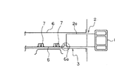
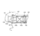
図において、1はバンパビーム、2はバンパステー、3は車体フレームであり、バンパビーム1は溶接等の適宜固着手段でバンパステー2に固定され、バンパステー2の嵌挿部2aがボックス状閉断面を有する車体フレーム3内に嵌挿される構成となっている。また車体側には図示のようにバンパステー2およびバンパビーム1を固定するための複数の埋め込みボルト4が取付けられており、このボルト4がバンパステー2の後述する車体取付面2cに開けた孔5を貫通し反対のバンパビーム側から図示せぬナットによりバンパビーム1およびバンパステー2の後述するビーム取付面2bに明けた孔5を通してバンパビームおよびバンパステー2を車体に締結する。
【0010】
バンパビーム1はアルミまたはその合金等からなる軽合金等で押し出し成形され、所定の断面形状を有し車体幅方向に長い形状をしている。
バンパステー2もバンパビーム1と同様にアルミまたは軽合金等で一体成形されており、バンパステー2は、バンパビーム1と当接する左右に伸びたビーム取付面2bを備え、そのビーム取付面2bと略平行でかつ一定距離離間して形成した車体取付面2cを備えている。車体取付面2cには、車体フレーム3内に嵌挿する上下に開口した嵌挿部2aが形成されており、前記車体取付面2cは、車体側前部との当接面として構成されている。また、バンパステー2には平面視において図2に示すように、車体フレーム3の左右側壁3L、3Rと同一直線上に対応する位置に補強リブ2dが形成されており、この補強リブ2dによってバンパステー2内を三つのブロックに区画し、中央部の区画はバンパステー2内の中空部と一体に形成され、この中央部が嵌挿部2aとして形成されている。このバンパステー2は上下方向の押し出し成形によって製造される。
【0011】
車体フレーム3は、前記嵌挿部2aを嵌挿することができるボックス状の閉断面を形成しており、バンパステー2の嵌挿部2aを嵌挿した状態の嵌挿部2aの端部に対応する位置に、嵌挿部2a端部と対向する係止部材(リンフォースメント)6が固定されている。このリンフォースメント6は本例では車体側のクロスメンバを固定するための取付ブラケットを兼用しており、バンパステー2の嵌合部端部に対応する部位には起立した係止部としてのフランジ6aが形成され、嵌挿部2aの後方への移動を阻止できるようになっている。また取付ブラケット6にはクロスメンバを固定するためのナット7が溶着固定されている。
【0012】
上記の構成からなるバンパ取付構造において、衝突時には図4に示すようにバンパステー2の嵌挿部2aの端面がリンフォースメント6のフランジ6aに当接し、それ以上の移動を阻止された状態でバンパビーム1、バンパステー2さらには車体フレーム3が変形し、この変形によって衝撃エネルギが吸収される。またバンパステー2の補強リブ2dが図2に示すように車体フレーム3の側壁と同一直線上にあるため、バンパステー2の補強リブ2dから直接車体フレーム3の側壁3L、3Rに荷重を伝達することができ、衝突時の抗力を与えることができる。なお、バンパステー2を車体に取り付ける際に、本例のような構成を採用すると、バンパステー2を車体フレーム3内に挿通して仮止め状態とすることができるため組付け作業性が向上する。
【0013】
なお、上記各実施形態は本発明の実施形態の内の例示に過ぎず、他の形態とすることもできる。例えば、上記実施形態ではフロント側のバンパ取付構造について説明したが、リヤ側のバンパ取付構造にも適用できることは言うまでもなく、またバンパビームの断面形状等も変更することが可能である。またリンフォースメントもクロスメンバ取付用ブラケットと兼用することなく、単独部品とすることも可能であり、また嵌挿部と当接する係止部(フランジ)の高さも自由に変更することができる。
【0014】
【発明の効果】
以上詳細に述べた如く本発明によれば、車体フレームの断面内に嵌挿しているバンパステーの嵌挿部全体を衝撃吸収体として機能させることができ、また車体フレーム全体の抗力を向上させることができる。また、バンパステーは車体に対して面結合されるので荷重を確実に受け取ることができるとともに、捩じり剛性も向上する。リンフォースメントとして既存のクロスメンバ取付用ブラケットを使用することで部品点数の軽減を図ることができる。バンパステーの断面内に補強リブを設けたことでバンパステーの強度を向上することができるとともに、補強リブを車体フレームの側壁と同一直線状とすることで、衝突荷重を補強リブから車体フレームにダイレクトに伝達することができる。また全体として構造が簡略化され、さらに、取付作業も向上する、等の優れた効果を奏することができる。
【図面の簡単な説明】
【図1】実施形態としての自動車のフロント側のバンパ取付構造の斜視図である。
【図2】同バンパ取付部の平面断面図である。
【図3】図2中のA−A断面図である。
【図4】衝突時のバンパ取付部の変形状態を説明する図である。
【図5】従来のバンパ取付部の断面図である。
【図6】他の従来のバンパ取付部の断面図である。
【符号の説明】
1 バンパビーム
2 バンパステー
3 車体フレーム
4 埋め込みボルト
5 孔
6 係止部材(リンフォースメント、取付ブラケット)
7 ナット[0001]
BACKGROUND OF THE INVENTION
The present invention relates to a bumper mounting structure for a vehicle, in particular, while receiving reliably load during an impact, to a bumper mounting structure capable of performing a shock absorbing efficiently.
[0002]
[Prior art]
As a conventional bumper mounting structure for an automobile, a structure in which a bumper beam and a bumper stay are sub-assembled on a bumper face in advance and mounted on a vehicle body is employed (Japanese Patent Laid-Open No. 6-227333). Because the sub-assembled bumper increases in weight, one worker holds the sub-assembly and the other worker secures it to the body frame with bolts, etc., during installation work. There is. In addition, because the reinforcement rib or vertical wall of the bumper stay is offset from the vertical wall of the body frame, the impact load at the time of collision is transmitted to the body frame as an out-of-plane load, absorbing the collision energy. There is a problem in terms of.
[0003]
For this reason, a bumper mounting structure has been proposed that has good mounting workability and can efficiently absorb collision energy (Japanese Patent Laid-Open Nos. 9-86309, 11-208392, etc.).
The bumper mounting structure of Japanese Patent Laid-Open No. 9-86309 will be described with reference to FIG. 5. FIG. 5 is a side sectional view, in which 101 is a bumper beam formed from a light alloy such as an aluminum alloy, 101a is a bumper face, 102 is a bumper stay formed from a light alloy such as an aluminum alloy, and 103 is a body frame. In this bumper mounting structure, a bumper stay 102 formed by light metal extrusion molding is inserted into a box-shaped
[0004]
Further, as shown in the plan view of FIG. 6, the bumper mounting structure disclosed in Japanese Patent Laid-Open No. 11-208392 is provided at the front and rear end portions of side members (vehicle body frames) 203 having closed cross-sectional shapes respectively arranged on the left and right sides of the vehicle body. A bumper reinforcement mounting structure that attaches both ends of a bumper reinforcement (bumper beam) 201 via a
[0005]
[Problems to be solved by the invention]
However, in the former structure, it is the front part (the part on the left side of the
[0006]
In view of this, the present invention provides a configuration in which the rear end portion of the insertion portion that is inserted into the vehicle body frame is locked by a locking member (reinforcement) that is fixed in the cross section of the vehicle body frame, thereby It is an object of the present invention to provide a bumper mounting structure that enables an entire insertion portion of a bumper stay that is inserted into a shock absorber to function as an impact absorber, and to solve the above problems. Furthermore, the bumper stay has the same cross-sectional shape in the vertical direction, and the reinforcement ribs are arranged in the same straight line as the side wall of the vehicle body frame in the cross section, so that the stay strength can be improved and the reinforcement ribs It is an object of the present invention to provide a bumper mounting structure capable of directly transmitting a collision load from a rib to a vehicle body frame and to solve the above-mentioned problems.
[0007]
[Means for Solving the Problems]
For this reason, the problem-solving means adopted by the present invention is a bumper mounting structure in which a bumper beam is attached to an end portion of a vehicle body frame having a closed cross-sectional shape disposed on both left and right sides of a vehicle body via an extruded bumper stay. And a fitting insertion part that protrudes from the rear part of the main body part and is fitted into the vehicle body frame, and the main body part is arranged at a predetermined distance from the beam attachment surface to which the bumper beam is fixed and the beam attachment surface. A vehicle body mounting surface, and the fitting portion is formed on the vehicle body mounting surface, and a locking member is provided in the vehicle body frame for preventing movement of the fitting insertion portion in the event of a collision. The member is constituted by a bracket for attaching a cross member for connecting the left and right body frames, and the bracket has a locking portion for receiving the end of the fitting insertion portion of the bumper stay. Which is a bumper mounting structure characterized. In addition, the bumper stay has a bumper mounting structure characterized in that the bumper stay has the same cross-sectional shape in the vertical direction, and reinforcing ribs are arranged in a position that is collinear with the side wall of the vehicle body frame in the cross-section. The vertical cross section of the bumper stay is divided into three blocks by reinforcing ribs, the central block is continuous from the main body portion to the fitting insertion portion, and the left and right blocks form a vehicle body mounting surface. Bumper mounting structure. And in this invention which consists of the above solution means, at the time of a collision, the edge part of the insertion part inserted in a body frame is locked by the locking member fixed in the section of a body frame. The entire insertion portion of the bumper stay that is inserted in the cross section of the vehicle body frame can function as an impact absorber. In addition, the bumper stay has the same cross-sectional shape in the vertical direction, and the reinforcing rib is arranged in the same straight line as the side wall of the vehicle body frame in the cross section, so that the collision load is directly transmitted from the reinforcing rib to the vehicle body frame. Can do.
[0008]
DETAILED DESCRIPTION OF THE INVENTION
Hereinafter, embodiments of the present invention will be described with reference to the drawings.
1 to 4 are views showing an embodiment of the present invention. FIG. 1 is a perspective view of a bumper attachment portion attached to the front of a vehicle body, FIG. 2 is a plan view thereof, and FIG. 3 is A in FIG. FIG. 4 is a side view for explaining the state of energy absorption at the time of collision. In the description, “front” and “rear” correspond to the longitudinal direction of the vehicle.
[0009]
In the figure, 1 is a bumper beam, 2 is a bumper stay, 3 is a body frame, the bumper beam 1 is fixed to the bumper stay 2 by an appropriate fixing means such as welding, and the
[0010]
The bumper beam 1 is extruded from a light alloy made of aluminum or an alloy thereof, and has a predetermined cross-sectional shape and a long shape in the vehicle body width direction.
Similarly to the bumper beam 1, the
[0011]
The
[0012]
In the bumper mounting structure having the above-described configuration, the bumper beam is in a state where the end face of the
[0013]
In addition, each said embodiment is only the illustration in embodiment of this invention, It can also be set as another form. For example, in the above embodiment, the front-side bumper mounting structure has been described. However, it goes without saying that the present invention can also be applied to the rear-side bumper mounting structure, and the bumper beam cross-sectional shape and the like can be changed. Also, the reinforcement can be made as a single component without being used also as the cross member mounting bracket, and the height of the engaging portion (flange) contacting the fitting insertion portion can be freely changed.
[0014]
【The invention's effect】
As described above in detail, according to the present invention, the entire insertion portion of the bumper stay fitted in the cross section of the vehicle body frame can function as an impact absorber, and the drag of the entire vehicle body frame can be improved. it can. In addition, since the bumper stay is surface-coupled to the vehicle body, the load can be reliably received and the torsional rigidity is also improved. The number of parts can be reduced by using an existing cross member mounting bracket as reinforcement. By providing reinforcing ribs in the section of the bumper stay, the strength of the bumper stay can be improved, and by making the reinforcing rib the same straight line as the side wall of the body frame, the collision load can be directly applied from the reinforcing rib to the body frame. Can communicate. Moreover, the structure can be simplified as a whole, and further excellent effects such as improvement of the mounting work can be obtained.
[Brief description of the drawings]
FIG. 1 is a perspective view of a bumper mounting structure on the front side of an automobile as an embodiment.
FIG. 2 is a plan sectional view of the bumper mounting portion.
FIG. 3 is a cross-sectional view taken along the line AA in FIG.
FIG. 4 is a diagram illustrating a deformed state of a bumper mounting portion at the time of a collision.
FIG. 5 is a cross-sectional view of a conventional bumper mounting portion.
FIG. 6 is a cross-sectional view of another conventional bumper mounting portion.
[Explanation of symbols]
1
7 Nut
Claims (3)
Priority Applications (1)
| Application Number | Priority Date | Filing Date | Title |
|---|---|---|---|
| JP2001033062A JP4589543B2 (en) | 2001-02-09 | 2001-02-09 | Bumper mounting structure |
Applications Claiming Priority (1)
| Application Number | Priority Date | Filing Date | Title |
|---|---|---|---|
| JP2001033062A JP4589543B2 (en) | 2001-02-09 | 2001-02-09 | Bumper mounting structure |
Publications (2)
| Publication Number | Publication Date |
|---|---|
| JP2002234409A JP2002234409A (en) | 2002-08-20 |
| JP4589543B2 true JP4589543B2 (en) | 2010-12-01 |
Family
ID=18896871
Family Applications (1)
| Application Number | Title | Priority Date | Filing Date |
|---|---|---|---|
| JP2001033062A Expired - Fee Related JP4589543B2 (en) | 2001-02-09 | 2001-02-09 | Bumper mounting structure |
Country Status (1)
| Country | Link |
|---|---|
| JP (1) | JP4589543B2 (en) |
Families Citing this family (8)
| Publication number | Priority date | Publication date | Assignee | Title |
|---|---|---|---|---|
| JP4114468B2 (en) * | 2002-12-05 | 2008-07-09 | トヨタ自動車株式会社 | Bumper support structure for vehicles |
| JP2005205991A (en) * | 2004-01-21 | 2005-08-04 | Honda Motor Co Ltd | Bumper beam structure |
| JP3962040B2 (en) * | 2004-07-20 | 2007-08-22 | 本田技研工業株式会社 | Bumper beam mounting structure for vehicles |
| KR100747029B1 (en) * | 2005-11-25 | 2007-08-07 | 현대자동차주식회사 | Front end part structure of vehicle |
| JP5313817B2 (en) * | 2008-09-15 | 2013-10-09 | 住友軽金属工業株式会社 | Bumper stay |
| JP5267929B2 (en) | 2008-09-30 | 2013-08-21 | スズキ株式会社 | Vehicle front structure |
| JP5880320B2 (en) * | 2012-07-06 | 2016-03-09 | トヨタ自動車株式会社 | Body front structure |
| KR101399334B1 (en) | 2012-09-24 | 2014-06-27 | 주식회사 성우하이텍 | A bumper beam unit for vehicles |
Citations (4)
| Publication number | Priority date | Publication date | Assignee | Title |
|---|---|---|---|---|
| JPS60156058U (en) * | 1984-03-28 | 1985-10-17 | ダイハツ工業株式会社 | Bumper mounting structure |
| JPH0257751U (en) * | 1988-10-20 | 1990-04-25 | ||
| JPH08108815A (en) * | 1994-10-07 | 1996-04-30 | Mitsubishi Alum Co Ltd | Bumper mounting bracket for automobile |
| JPH11208392A (en) * | 1998-01-26 | 1999-08-03 | Nissan Motor Co Ltd | Mounting structure of bumper reinforcement |
-
2001
- 2001-02-09 JP JP2001033062A patent/JP4589543B2/en not_active Expired - Fee Related
Patent Citations (4)
| Publication number | Priority date | Publication date | Assignee | Title |
|---|---|---|---|---|
| JPS60156058U (en) * | 1984-03-28 | 1985-10-17 | ダイハツ工業株式会社 | Bumper mounting structure |
| JPH0257751U (en) * | 1988-10-20 | 1990-04-25 | ||
| JPH08108815A (en) * | 1994-10-07 | 1996-04-30 | Mitsubishi Alum Co Ltd | Bumper mounting bracket for automobile |
| JPH11208392A (en) * | 1998-01-26 | 1999-08-03 | Nissan Motor Co Ltd | Mounting structure of bumper reinforcement |
Also Published As
| Publication number | Publication date |
|---|---|
| JP2002234409A (en) | 2002-08-20 |
Similar Documents
| Publication | Publication Date | Title |
|---|---|---|
| US8857902B2 (en) | Front vehicle body structure | |
| KR101588752B1 (en) | Vehicle body reinforcing structure for coping with small overlap collision | |
| KR101097018B1 (en) | Automobile door with strengthened side collision performance | |
| US7735902B2 (en) | Front structure of a motor vehicle | |
| KR101786676B1 (en) | Front vehicle body structure | |
| CN210000408U (en) | Front engine room assembly for electric automobile, automobile body assembly and electric automobile | |
| KR101703612B1 (en) | Front vehicle body reinforcing structure and assembling method thereof | |
| JP4589543B2 (en) | Bumper mounting structure | |
| JP4687138B2 (en) | Vehicle front structure | |
| JP3870677B2 (en) | Shock absorber for moving body | |
| WO2024028099A1 (en) | Side extension for crash management system | |
| KR101085819B1 (en) | A mounting structure of bumper stay | |
| JP2005231436A (en) | Front body structure of vehicle | |
| JP2007008346A (en) | Vehicle rear part structure | |
| JP4106935B2 (en) | Front body structure of automobile | |
| JP2008132831A (en) | Front part structure for vehicle | |
| JP2002274299A (en) | Frame tip structure | |
| KR100256541B1 (en) | Bumper stay | |
| JP2000001150A (en) | Bumper unit of automobile | |
| CN210126556U (en) | Aluminum alloy frame front section structure for car and car | |
| CN215883820U (en) | Upper vehicle body structure | |
| KR100412351B1 (en) | Combination structure of Front pillar | |
| KR0178912B1 (en) | Front bumper reinforcement structure of automobile | |
| KR101005461B1 (en) | Crash box in automotive bumper system | |
| KR100258620B1 (en) | Bumper conbinating structure |
Legal Events
| Date | Code | Title | Description |
|---|---|---|---|
| A621 | Written request for application examination |
Free format text: JAPANESE INTERMEDIATE CODE: A621 Effective date: 20080121 |
|
| A977 | Report on retrieval |
Free format text: JAPANESE INTERMEDIATE CODE: A971007 Effective date: 20100430 |
|
| A131 | Notification of reasons for refusal |
Free format text: JAPANESE INTERMEDIATE CODE: A131 Effective date: 20100525 |
|
| A521 | Written amendment |
Free format text: JAPANESE INTERMEDIATE CODE: A523 Effective date: 20100721 |
|
| TRDD | Decision of grant or rejection written | ||
| A01 | Written decision to grant a patent or to grant a registration (utility model) |
Free format text: JAPANESE INTERMEDIATE CODE: A01 Effective date: 20100907 |
|
| A01 | Written decision to grant a patent or to grant a registration (utility model) |
Free format text: JAPANESE INTERMEDIATE CODE: A01 |
|
| A61 | First payment of annual fees (during grant procedure) |
Free format text: JAPANESE INTERMEDIATE CODE: A61 Effective date: 20100910 |
|
| R150 | Certificate of patent or registration of utility model |
Ref document number: 4589543 Country of ref document: JP Free format text: JAPANESE INTERMEDIATE CODE: R150 Free format text: JAPANESE INTERMEDIATE CODE: R150 |
|
| FPAY | Renewal fee payment (event date is renewal date of database) |
Free format text: PAYMENT UNTIL: 20130917 Year of fee payment: 3 |
|
| R250 | Receipt of annual fees |
Free format text: JAPANESE INTERMEDIATE CODE: R250 |
|
| R250 | Receipt of annual fees |
Free format text: JAPANESE INTERMEDIATE CODE: R250 |
|
| S531 | Written request for registration of change of domicile |
Free format text: JAPANESE INTERMEDIATE CODE: R313531 |
|
| R350 | Written notification of registration of transfer |
Free format text: JAPANESE INTERMEDIATE CODE: R350 |
|
| R250 | Receipt of annual fees |
Free format text: JAPANESE INTERMEDIATE CODE: R250 |
|
| R250 | Receipt of annual fees |
Free format text: JAPANESE INTERMEDIATE CODE: R250 |
|
| S533 | Written request for registration of change of name |
Free format text: JAPANESE INTERMEDIATE CODE: R313533 |
|
| R350 | Written notification of registration of transfer |
Free format text: JAPANESE INTERMEDIATE CODE: R350 |
|
| R250 | Receipt of annual fees |
Free format text: JAPANESE INTERMEDIATE CODE: R250 |
|
| R250 | Receipt of annual fees |
Free format text: JAPANESE INTERMEDIATE CODE: R250 |
|
| R250 | Receipt of annual fees |
Free format text: JAPANESE INTERMEDIATE CODE: R250 |
|
| LAPS | Cancellation because of no payment of annual fees |