EP1266701A2 - Katalytische Beschichtung von strukturierten Wärmetauschern - Google Patents
Katalytische Beschichtung von strukturierten Wärmetauschern Download PDFInfo
- Publication number
- EP1266701A2 EP1266701A2 EP02011805A EP02011805A EP1266701A2 EP 1266701 A2 EP1266701 A2 EP 1266701A2 EP 02011805 A EP02011805 A EP 02011805A EP 02011805 A EP02011805 A EP 02011805A EP 1266701 A2 EP1266701 A2 EP 1266701A2
- Authority
- EP
- European Patent Office
- Prior art keywords
- heat exchanger
- material component
- printing
- catalytically active
- active material
- Prior art date
- Legal status (The legal status is an assumption and is not a legal conclusion. Google has not performed a legal analysis and makes no representation as to the accuracy of the status listed.)
- Granted
Links
- 230000003197 catalytic effect Effects 0.000 title claims abstract description 15
- 238000000576 coating method Methods 0.000 title claims description 21
- 239000011248 coating agent Substances 0.000 title claims description 20
- 239000000463 material Substances 0.000 claims abstract description 29
- 239000011149 active material Substances 0.000 claims abstract description 13
- 239000011230 binding agent Substances 0.000 claims abstract description 9
- 239000000919 ceramic Substances 0.000 claims abstract description 6
- 238000000034 method Methods 0.000 claims description 34
- 238000007639 printing Methods 0.000 claims description 25
- 230000008569 process Effects 0.000 claims description 19
- 239000005871 repellent Substances 0.000 claims description 12
- 238000001035 drying Methods 0.000 claims description 9
- 239000000446 fuel Substances 0.000 claims description 9
- 238000007649 pad printing Methods 0.000 claims description 9
- 238000001354 calcination Methods 0.000 claims description 8
- 239000000203 mixture Substances 0.000 claims description 5
- 238000004519 manufacturing process Methods 0.000 abstract description 4
- 239000003054 catalyst Substances 0.000 description 25
- 239000010410 layer Substances 0.000 description 14
- 229920001296 polysiloxane Polymers 0.000 description 10
- 239000006072 paste Substances 0.000 description 8
- 239000007788 liquid Substances 0.000 description 6
- 229910052751 metal Inorganic materials 0.000 description 6
- 239000002184 metal Substances 0.000 description 6
- 229920001343 polytetrafluoroethylene Polymers 0.000 description 5
- 239000004810 polytetrafluoroethylene Substances 0.000 description 5
- 239000000725 suspension Substances 0.000 description 5
- 230000000694 effects Effects 0.000 description 4
- OKKJLVBELUTLKV-UHFFFAOYSA-N Methanol Chemical compound OC OKKJLVBELUTLKV-UHFFFAOYSA-N 0.000 description 3
- -1 Polytetrafluoroethylene Polymers 0.000 description 3
- 239000012530 fluid Substances 0.000 description 3
- 239000007921 spray Substances 0.000 description 3
- 230000008646 thermal stress Effects 0.000 description 3
- KXGFMDJXCMQABM-UHFFFAOYSA-N 2-methoxy-6-methylphenol Chemical compound [CH]OC1=CC=CC([CH])=C1O KXGFMDJXCMQABM-UHFFFAOYSA-N 0.000 description 2
- 239000004925 Acrylic resin Substances 0.000 description 2
- 229920000178 Acrylic resin Polymers 0.000 description 2
- 229920001800 Shellac Polymers 0.000 description 2
- 230000001070 adhesive effect Effects 0.000 description 2
- 230000008901 benefit Effects 0.000 description 2
- 238000006243 chemical reaction Methods 0.000 description 2
- 238000009833 condensation Methods 0.000 description 2
- 230000005494 condensation Effects 0.000 description 2
- 239000003822 epoxy resin Substances 0.000 description 2
- 229920002313 fluoropolymer Polymers 0.000 description 2
- 239000012528 membrane Substances 0.000 description 2
- 230000006855 networking Effects 0.000 description 2
- 230000000737 periodic effect Effects 0.000 description 2
- 229920001568 phenolic resin Polymers 0.000 description 2
- 239000005011 phenolic resin Substances 0.000 description 2
- 229920000647 polyepoxide Polymers 0.000 description 2
- ZLGIYFNHBLSMPS-ATJNOEHPSA-N shellac Chemical compound OCCCCCC(O)C(O)CCCCCCCC(O)=O.C1C23[C@H](C(O)=O)CCC2[C@](C)(CO)[C@@H]1C(C(O)=O)=C[C@@H]3O ZLGIYFNHBLSMPS-ATJNOEHPSA-N 0.000 description 2
- 229940113147 shellac Drugs 0.000 description 2
- 239000004208 shellac Substances 0.000 description 2
- 235000013874 shellac Nutrition 0.000 description 2
- 229920002379 silicone rubber Polymers 0.000 description 2
- 239000004945 silicone rubber Substances 0.000 description 2
- 238000005507 spraying Methods 0.000 description 2
- 239000000126 substance Substances 0.000 description 2
- XLYOFNOQVPJJNP-UHFFFAOYSA-N water Chemical compound O XLYOFNOQVPJJNP-UHFFFAOYSA-N 0.000 description 2
- 229910018072 Al 2 O 3 Inorganic materials 0.000 description 1
- OKTJSMMVPCPJKN-UHFFFAOYSA-N Carbon Chemical compound [C] OKTJSMMVPCPJKN-UHFFFAOYSA-N 0.000 description 1
- 229910052684 Cerium Inorganic materials 0.000 description 1
- RYGMFSIKBFXOCR-UHFFFAOYSA-N Copper Chemical compound [Cu] RYGMFSIKBFXOCR-UHFFFAOYSA-N 0.000 description 1
- 229910004298 SiO 2 Inorganic materials 0.000 description 1
- GEIAQOFPUVMAGM-UHFFFAOYSA-N ZrO Inorganic materials [Zr]=O GEIAQOFPUVMAGM-UHFFFAOYSA-N 0.000 description 1
- 239000000654 additive Substances 0.000 description 1
- 239000000853 adhesive Substances 0.000 description 1
- 238000004026 adhesive bonding Methods 0.000 description 1
- 239000004840 adhesive resin Substances 0.000 description 1
- 229920006223 adhesive resin Polymers 0.000 description 1
- 230000009286 beneficial effect Effects 0.000 description 1
- 229910052799 carbon Inorganic materials 0.000 description 1
- 239000012876 carrier material Substances 0.000 description 1
- 229910010293 ceramic material Inorganic materials 0.000 description 1
- 150000001875 compounds Chemical class 0.000 description 1
- 230000001276 controlling effect Effects 0.000 description 1
- 229910052802 copper Inorganic materials 0.000 description 1
- 239000010949 copper Substances 0.000 description 1
- 238000004132 cross linking Methods 0.000 description 1
- 230000009849 deactivation Effects 0.000 description 1
- 238000010586 diagram Methods 0.000 description 1
- 239000000428 dust Substances 0.000 description 1
- 239000010411 electrocatalyst Substances 0.000 description 1
- 239000007789 gas Substances 0.000 description 1
- 239000001257 hydrogen Substances 0.000 description 1
- 229910052739 hydrogen Inorganic materials 0.000 description 1
- 125000004435 hydrogen atom Chemical class [H]* 0.000 description 1
- 150000004679 hydroxides Chemical class 0.000 description 1
- 238000007654 immersion Methods 0.000 description 1
- 239000012535 impurity Substances 0.000 description 1
- 238000005304 joining Methods 0.000 description 1
- 230000007774 longterm Effects 0.000 description 1
- 230000000873 masking effect Effects 0.000 description 1
- 150000002739 metals Chemical class 0.000 description 1
- 239000003595 mist Substances 0.000 description 1
- 238000007645 offset printing Methods 0.000 description 1
- 238000010979 pH adjustment Methods 0.000 description 1
- 239000004033 plastic Substances 0.000 description 1
- 239000002574 poison Substances 0.000 description 1
- 231100000614 poison Toxicity 0.000 description 1
- 231100000572 poisoning Toxicity 0.000 description 1
- 230000000607 poisoning effect Effects 0.000 description 1
- 239000005518 polymer electrolyte Substances 0.000 description 1
- 239000010970 precious metal Substances 0.000 description 1
- 238000003825 pressing Methods 0.000 description 1
- 230000005855 radiation Effects 0.000 description 1
- 229910001404 rare earth metal oxide Inorganic materials 0.000 description 1
- 230000009257 reactivity Effects 0.000 description 1
- 230000009467 reduction Effects 0.000 description 1
- 230000001105 regulatory effect Effects 0.000 description 1
- 230000000717 retained effect Effects 0.000 description 1
- 238000007650 screen-printing Methods 0.000 description 1
- 229920002050 silicone resin Polymers 0.000 description 1
- 239000002356 single layer Substances 0.000 description 1
- 239000007787 solid Substances 0.000 description 1
- 230000006641 stabilisation Effects 0.000 description 1
- 238000011105 stabilization Methods 0.000 description 1
- 229920003002 synthetic resin Polymers 0.000 description 1
- 239000000057 synthetic resin Substances 0.000 description 1
- 238000009736 wetting Methods 0.000 description 1
- 239000010457 zeolite Substances 0.000 description 1
Images

Classifications
-
- F—MECHANICAL ENGINEERING; LIGHTING; HEATING; WEAPONS; BLASTING
- F28—HEAT EXCHANGE IN GENERAL
- F28F—DETAILS OF HEAT-EXCHANGE AND HEAT-TRANSFER APPARATUS, OF GENERAL APPLICATION
- F28F3/00—Plate-like or laminated elements; Assemblies of plate-like or laminated elements
- F28F3/02—Elements or assemblies thereof with means for increasing heat-transfer area, e.g. with fins, with recesses, with corrugations
- F28F3/04—Elements or assemblies thereof with means for increasing heat-transfer area, e.g. with fins, with recesses, with corrugations the means being integral with the element
- F28F3/042—Elements or assemblies thereof with means for increasing heat-transfer area, e.g. with fins, with recesses, with corrugations the means being integral with the element in the form of local deformations of the element
- F28F3/046—Elements or assemblies thereof with means for increasing heat-transfer area, e.g. with fins, with recesses, with corrugations the means being integral with the element in the form of local deformations of the element the deformations being linear, e.g. corrugations
-
- B—PERFORMING OPERATIONS; TRANSPORTING
- B01—PHYSICAL OR CHEMICAL PROCESSES OR APPARATUS IN GENERAL
- B01J—CHEMICAL OR PHYSICAL PROCESSES, e.g. CATALYSIS OR COLLOID CHEMISTRY; THEIR RELEVANT APPARATUS
- B01J19/00—Chemical, physical or physico-chemical processes in general; Their relevant apparatus
- B01J19/24—Stationary reactors without moving elements inside
- B01J19/248—Reactors comprising multiple separated flow channels
- B01J19/249—Plate-type reactors
-
- B—PERFORMING OPERATIONS; TRANSPORTING
- B01—PHYSICAL OR CHEMICAL PROCESSES OR APPARATUS IN GENERAL
- B01J—CHEMICAL OR PHYSICAL PROCESSES, e.g. CATALYSIS OR COLLOID CHEMISTRY; THEIR RELEVANT APPARATUS
- B01J35/00—Catalysts, in general, characterised by their form or physical properties
- B01J35/50—Catalysts, in general, characterised by their form or physical properties characterised by their shape or configuration
- B01J35/56—Foraminous structures having flow-through passages or channels, e.g. grids or three-dimensional monoliths
-
- F—MECHANICAL ENGINEERING; LIGHTING; HEATING; WEAPONS; BLASTING
- F28—HEAT EXCHANGE IN GENERAL
- F28D—HEAT-EXCHANGE APPARATUS, NOT PROVIDED FOR IN ANOTHER SUBCLASS, IN WHICH THE HEAT-EXCHANGE MEDIA DO NOT COME INTO DIRECT CONTACT
- F28D9/00—Heat-exchange apparatus having stationary plate-like or laminated conduit assemblies for both heat-exchange media, the media being in contact with different sides of a conduit wall
- F28D9/0031—Heat-exchange apparatus having stationary plate-like or laminated conduit assemblies for both heat-exchange media, the media being in contact with different sides of a conduit wall the conduits for one heat-exchange medium being formed by paired plates touching each other
- F28D9/0043—Heat-exchange apparatus having stationary plate-like or laminated conduit assemblies for both heat-exchange media, the media being in contact with different sides of a conduit wall the conduits for one heat-exchange medium being formed by paired plates touching each other the plates having openings therein for circulation of at least one heat-exchange medium from one conduit to another
- F28D9/005—Heat-exchange apparatus having stationary plate-like or laminated conduit assemblies for both heat-exchange media, the media being in contact with different sides of a conduit wall the conduits for one heat-exchange medium being formed by paired plates touching each other the plates having openings therein for circulation of at least one heat-exchange medium from one conduit to another the plates having openings therein for both heat-exchange media
-
- H—ELECTRICITY
- H01—ELECTRIC ELEMENTS
- H01M—PROCESSES OR MEANS, e.g. BATTERIES, FOR THE DIRECT CONVERSION OF CHEMICAL ENERGY INTO ELECTRICAL ENERGY
- H01M8/00—Fuel cells; Manufacture thereof
- H01M8/06—Combination of fuel cells with means for production of reactants or for treatment of residues
- H01M8/0606—Combination of fuel cells with means for production of reactants or for treatment of residues with means for production of gaseous reactants
- H01M8/0612—Combination of fuel cells with means for production of reactants or for treatment of residues with means for production of gaseous reactants from carbon-containing material
- H01M8/0625—Combination of fuel cells with means for production of reactants or for treatment of residues with means for production of gaseous reactants from carbon-containing material in a modular combined reactor/fuel cell structure
- H01M8/0631—Reactor construction specially adapted for combination reactor/fuel cell
-
- B—PERFORMING OPERATIONS; TRANSPORTING
- B01—PHYSICAL OR CHEMICAL PROCESSES OR APPARATUS IN GENERAL
- B01J—CHEMICAL OR PHYSICAL PROCESSES, e.g. CATALYSIS OR COLLOID CHEMISTRY; THEIR RELEVANT APPARATUS
- B01J2219/00—Chemical, physical or physico-chemical processes in general; Their relevant apparatus
- B01J2219/24—Stationary reactors without moving elements inside
- B01J2219/2401—Reactors comprising multiple separate flow channels
- B01J2219/245—Plate-type reactors
- B01J2219/2451—Geometry of the reactor
- B01J2219/2456—Geometry of the plates
- B01J2219/2458—Flat plates, i.e. plates which are not corrugated or otherwise structured, e.g. plates with cylindrical shape
-
- B—PERFORMING OPERATIONS; TRANSPORTING
- B01—PHYSICAL OR CHEMICAL PROCESSES OR APPARATUS IN GENERAL
- B01J—CHEMICAL OR PHYSICAL PROCESSES, e.g. CATALYSIS OR COLLOID CHEMISTRY; THEIR RELEVANT APPARATUS
- B01J2219/00—Chemical, physical or physico-chemical processes in general; Their relevant apparatus
- B01J2219/24—Stationary reactors without moving elements inside
- B01J2219/2401—Reactors comprising multiple separate flow channels
- B01J2219/245—Plate-type reactors
- B01J2219/2451—Geometry of the reactor
- B01J2219/2456—Geometry of the plates
- B01J2219/2459—Corrugated plates
-
- B—PERFORMING OPERATIONS; TRANSPORTING
- B01—PHYSICAL OR CHEMICAL PROCESSES OR APPARATUS IN GENERAL
- B01J—CHEMICAL OR PHYSICAL PROCESSES, e.g. CATALYSIS OR COLLOID CHEMISTRY; THEIR RELEVANT APPARATUS
- B01J2219/00—Chemical, physical or physico-chemical processes in general; Their relevant apparatus
- B01J2219/24—Stationary reactors without moving elements inside
- B01J2219/2401—Reactors comprising multiple separate flow channels
- B01J2219/245—Plate-type reactors
- B01J2219/2461—Heat exchange aspects
-
- B—PERFORMING OPERATIONS; TRANSPORTING
- B01—PHYSICAL OR CHEMICAL PROCESSES OR APPARATUS IN GENERAL
- B01J—CHEMICAL OR PHYSICAL PROCESSES, e.g. CATALYSIS OR COLLOID CHEMISTRY; THEIR RELEVANT APPARATUS
- B01J2219/00—Chemical, physical or physico-chemical processes in general; Their relevant apparatus
- B01J2219/24—Stationary reactors without moving elements inside
- B01J2219/2401—Reactors comprising multiple separate flow channels
- B01J2219/245—Plate-type reactors
- B01J2219/2476—Construction materials
- B01J2219/2477—Construction materials of the catalysts
- B01J2219/2479—Catalysts coated on the surface of plates or inserts
-
- B—PERFORMING OPERATIONS; TRANSPORTING
- B05—SPRAYING OR ATOMISING IN GENERAL; APPLYING FLUENT MATERIALS TO SURFACES, IN GENERAL
- B05D—PROCESSES FOR APPLYING FLUENT MATERIALS TO SURFACES, IN GENERAL
- B05D1/00—Processes for applying liquids or other fluent materials
- B05D1/28—Processes for applying liquids or other fluent materials performed by transfer from the surfaces of elements carrying the liquid or other fluent material, e.g. brushes, pads, rollers
-
- H—ELECTRICITY
- H01—ELECTRIC ELEMENTS
- H01M—PROCESSES OR MEANS, e.g. BATTERIES, FOR THE DIRECT CONVERSION OF CHEMICAL ENERGY INTO ELECTRICAL ENERGY
- H01M8/00—Fuel cells; Manufacture thereof
- H01M8/04—Auxiliary arrangements, e.g. for control of pressure or for circulation of fluids
- H01M8/04007—Auxiliary arrangements, e.g. for control of pressure or for circulation of fluids related to heat exchange
- H01M8/04067—Heat exchange or temperature measuring elements, thermal insulation, e.g. heat pipes, heat pumps, fins
- H01M8/04074—Heat exchange unit structures specially adapted for fuel cell
-
- Y—GENERAL TAGGING OF NEW TECHNOLOGICAL DEVELOPMENTS; GENERAL TAGGING OF CROSS-SECTIONAL TECHNOLOGIES SPANNING OVER SEVERAL SECTIONS OF THE IPC; TECHNICAL SUBJECTS COVERED BY FORMER USPC CROSS-REFERENCE ART COLLECTIONS [XRACs] AND DIGESTS
- Y02—TECHNOLOGIES OR APPLICATIONS FOR MITIGATION OR ADAPTATION AGAINST CLIMATE CHANGE
- Y02E—REDUCTION OF GREENHOUSE GAS [GHG] EMISSIONS, RELATED TO ENERGY GENERATION, TRANSMISSION OR DISTRIBUTION
- Y02E60/00—Enabling technologies; Technologies with a potential or indirect contribution to GHG emissions mitigation
- Y02E60/30—Hydrogen technology
- Y02E60/50—Fuel cells
-
- Y—GENERAL TAGGING OF NEW TECHNOLOGICAL DEVELOPMENTS; GENERAL TAGGING OF CROSS-SECTIONAL TECHNOLOGIES SPANNING OVER SEVERAL SECTIONS OF THE IPC; TECHNICAL SUBJECTS COVERED BY FORMER USPC CROSS-REFERENCE ART COLLECTIONS [XRACs] AND DIGESTS
- Y02—TECHNOLOGIES OR APPLICATIONS FOR MITIGATION OR ADAPTATION AGAINST CLIMATE CHANGE
- Y02P—CLIMATE CHANGE MITIGATION TECHNOLOGIES IN THE PRODUCTION OR PROCESSING OF GOODS
- Y02P70/00—Climate change mitigation technologies in the production process for final industrial or consumer products
- Y02P70/50—Manufacturing or production processes characterised by the final manufactured product
-
- Y—GENERAL TAGGING OF NEW TECHNOLOGICAL DEVELOPMENTS; GENERAL TAGGING OF CROSS-SECTIONAL TECHNOLOGIES SPANNING OVER SEVERAL SECTIONS OF THE IPC; TECHNICAL SUBJECTS COVERED BY FORMER USPC CROSS-REFERENCE ART COLLECTIONS [XRACs] AND DIGESTS
- Y10—TECHNICAL SUBJECTS COVERED BY FORMER USPC
- Y10T—TECHNICAL SUBJECTS COVERED BY FORMER US CLASSIFICATION
- Y10T29/00—Metal working
- Y10T29/49—Method of mechanical manufacture
- Y10T29/4935—Heat exchanger or boiler making
Definitions
- the invention relates to a method for producing a coated, structured heat exchanger sheet for one Reactor in a fuel cell system.
- structured heat exchanger plates have been used for application of coatings usually spray, rinse or dip coated.
- spray coating occurs Coating mass loss of up to 50% due to overspray.
- structured heat exchangers made of spray-coated metal sheets that cover the entire surface are coated, layer flaking occurs at the points of contact on. Are such welded reactors flushed or dip-coated, so form at the contact points Deposits from the occurrence of thermal stresses also flake off easily.
- the object of the invention is therefore an inexpensive method for coating a structured heat exchanger plate for a rector at which a Catalyst discharge through mechanical and / or thermal Stress in the manufacture or operation of a fuel cell system is almost avoided.
- the present invention provides a solution to this problem Process for producing a coated, structured Heat exchanger sheet for a reactor in a fuel cell system with the features of claim 1.
- the further subclaims contain advantageous refinements the invention.
- Pad printing is about an indirect printing process, i.e. one plate, the cliché is used as a template on which the printed image as Deepening is present.
- the cliché is created using a Squeegees with a so-called printing paste or printing fluid flooded, which is then pulled off again with a knife.
- the printing paste or remains in the recesses of the cliché Hang hydraulic fluid.
- the coating of the heat exchanger plate with the catalytic Component can by one or more imprints in the entire scope of the sheet.
- the coating can also by coating the heat exchanger plates zone by zone.
- the individual layers can be created by multiple printing functionalize so that, for example, on the one hand at the reactor entrance another catalyst as applied at the reactor outlet, on the other hand, the amount of catalyst over the length of the sheet can be varied to build a gradient.
- this procedure is used selective control of sales and reactions within the Reactor.
- the catalytic component to be applied by pad printing contains a catalytically active and / or a water-repellent Material component.
- the coating with the respective Material components can be in mixed form or as a single layer take place, i.e. on the sheet metal is first a catalytically effective lower layer and then a water-repellent one Printed top layer containing material component. Because the pad printing is not flat, but in shape of patterns can be applied when done first Apply the catalytically active material component through this the following imprint of the water-repellent material component not completely covered, so that the reaction gases and / or vapors can still reach the catalyst and so that the catalytic activity is retained, but a "Catalyst flooding" i.e.
- metals from the sub-groups of the periodic table Ib, IIb, VIIb and / or VIIIb are preferably selected as the catalytically active material, which may also contain substances to which elements from other groups of the Periodic table, such as rare earth oxides for thermal stabilization of the catalyst.
- the at least one catalyst material component and / or catalyst-containing material component is preferably supported.
- support materials for catalysts such as ceramic, carbon, plastic, metal etc.
- Porous solids are particularly suitable, on the surface of which catalytically active material is deposited. Ceramic materials such as zeolites, Al 2 O 3 , SiO 2 , ZrO 2 , CeO 2 and / or mixtures thereof are particularly preferably used as carrier materials.
- the at least one water-repellent material preferably contains Silicones or silicone-containing materials, fluorinated polymers such as. Polytetrafluoroethylene or polytetrafluoroethylene-containing Materials, epoxy resin or epoxy resin containing Materials, phenolic resin or materials containing phenolic resin, Acrylic resin or materials containing acrylic resin, PUR adhesive materials or materials containing PUR adhesive or synthetic resin / shellac mixtures or resinous / shellac-containing Mixtures. Suitable in the field of fluorinated polymers especially polytetrafluoroethylene (PTFE) as water-repellent Component and binder for catalysts. In the field of Silicones are particularly preferably used as silicone resins have high long-term heat resistance in the area of application have to.
- PTFE polytetrafluoroethylene
- These operating temperatures are in the range between about 30 ° C to 650 ° C, preferably in the range between about 50 ° C up to 300 ° C.
- Another advantage is that the Use of precious metal as a catalytically active material component in combination with silicones as water-repellent Material components no signs of poisoning Catalyst poisons occur, e.g. when using of copper as a catalytic component is the case.
- the layer that the contains water-repellent material component one by the chemical substance itself has limited elasticity, the one Chipping or discharge of catalyst from the layer additionally prevented or largely reduced these effects.
- the Proportion of water-repellent material component in relation to the catalytically active material component and / or catalyst-containing Material component is 1 to 50 weight percent, preferably 5 to 25 percent by weight.
- the catalyst paste or suspension required for printing liquid can be at least one catalytically active Material component preferably contain a ceramic binder, which also crosslinks after calcination in air at about 500 ° C can be, and water.
- Ceramic binder especially oxides and / or hydroxides of Al, Ce, Si, Zr and / or Mixtures thereof, preference being given to those which can be networked.
- Contains the catalyst paste or suspension required for printing or liquid is a polymeric binder which is used in the degrades the temperatures required for calcining the calcination step and only one or more follow Drying steps. Use is an exception to this of PTFE as a polymeric binder because this material can withstand higher temperatures for a short time.
- additives such as for controlling the viscosity, the wetting behavior on the stamp or for pH adjustment, can in the printing paste, suspension or liquid also be present.
- the adjustment of the process parameters to the The printing process depends on the material, temperature and process step and can be done using standard printing skills be solved.
- the printing process itself is carried out at room temperature, where the print medium (the stamp or tampon) and the Coating mass (printing paste, suspension or liquid) not be heated.
- the heat exchanger plate can during the application of the catalytic Components can be heated up to 200 ° C. This advantageously requires a faster drying of the Coating compound, especially with multiple printing.
- the printing step is a drying step in a temperature range from about 100 to 200 ° C for better adhesion of the coating downstream.
- circulating air / continuous dryers but also radiation dryers, e.g. using infrared, be used.
- the drying time required is about the throughput speed of the sheet or strip is regulated. Further printing processes can follow the drying step connect.
- the calcining step that concludes the process performed at about 500 ° C, the final Drying and cross-linking in the coating contained ceramic binder contributes.
- the duration of the Calcination step ranges from 0.5 to 4 hours.
- Silicone or silicone-containing material that is used for the Calcination degrades the temperatures used, the must Calcination step before applying the silicone or silicone-containing Material. To dry the following applied silicone or silicone-containing layer is or one or more drying steps are added.
- the heat exchanger plates produced by the process according to the invention are equally suitable for use as Reactor in hydrogen, reformate and direct methanol operated Fuel cell systems.
Landscapes
- Chemical & Material Sciences (AREA)
- Engineering & Computer Science (AREA)
- Chemical Kinetics & Catalysis (AREA)
- Organic Chemistry (AREA)
- Physics & Mathematics (AREA)
- Thermal Sciences (AREA)
- Mechanical Engineering (AREA)
- General Engineering & Computer Science (AREA)
- Life Sciences & Earth Sciences (AREA)
- Manufacturing & Machinery (AREA)
- Sustainable Development (AREA)
- Sustainable Energy (AREA)
- Electrochemistry (AREA)
- General Chemical & Material Sciences (AREA)
- Materials Engineering (AREA)
- Catalysts (AREA)
- Inert Electrodes (AREA)
- Fuel Cell (AREA)
Abstract
Description
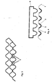
- Fig. 1
- die Draufsicht eines gewellten Bleches
- Fig. 2
- die Überlappung der Wellen beim Stapeln der Bleche und daraus resultierende Berührungspunkte
- Fig. 3
- einen Querschnitt durch 2 geschweißte, gewellte Bleche
- Fig. 4
- eine Prinzipskizze des Tampondrucks am Beispiel gewellter Bleche
Claims (10)
- Verfahren zur Herstellung eines beschichteten, strukturierten Wärmetauscherbleches für einen Reaktor in einem Brennstoffzellensytem, wobei eine katalytische Komponente in mindestens einer Schicht in kontinuierlicher oder diskontinuierlicher Weise mittels Tampondruck ausschließlich in die Vertiefungen und/oder Flanken des Wärmetauscherbleches aufgebracht wird.
- Verfahren nach Anspruch 1,
dadurch gekennzeichnet, daß die katalytische Komponente zonenweise aufgebracht wird. - Verfahren nach Anspruch 1,
dadurch gekennzeichnet, daß die katalytische Komponente eine katalytisch aktive Materialkomponente und/oder eine wasserabweisende Materialkomponente enthält. - Verfahren nach Anspruch 3,
dadurch gekennzeichnet, daß die katalytisch wirksame Materialkomponente bevorzugt geträgert vorliegt. - Verfahren nach Anspruch 3,
dadurch gekennzeichnet, daß die katalytisch wirksame Materialkomponente ein keramisches und/oder ein polymeres Bindemittel enthält. - Verfahren nach Anspruch 3, wobei die Zusammensetzung und/oder Konzentration der katalytisch aktiven Materialkomponente über die Länge des Wärmetauscherbleches variiert ist.
- Verfahren nach Anspruch 1,
dadurch gekennzeichnet, daß der Druckvorgang bei Raumtemperatur durchgeführt wird, wobei Druckmedium und Beschichtungsmasse nicht erwärmt werden. - Verfahren nach Anspruch 7,
dadurch gekennzeichnet, daß nach dem Druckschritt ein Trocknungsschritt in einem Temperaturbereich von etwa 100 bis 200°C durchgeführt wird. - Verfahren nach Anspruch 7,
dadurch gekennzeichnet, daß das Wärmetauscherblech während des Aufbringens der katalytischen Komponente beheizt wird. - Verfahren nach Anspruch 8 oder 9,
dadurch gekennzeichnet, daß der das Verfahren abschließende Calcinierungsschritt bei einer Temperatur von etwa 500°C durchgeführt wird.
Applications Claiming Priority (2)
| Application Number | Priority Date | Filing Date | Title |
|---|---|---|---|
| DE10129099A DE10129099A1 (de) | 2001-06-16 | 2001-06-16 | Katalytische Beschichtung von strukturierten Wärmetauscherblechen |
| DE10129099 | 2001-06-16 |
Publications (3)
| Publication Number | Publication Date |
|---|---|
| EP1266701A2 true EP1266701A2 (de) | 2002-12-18 |
| EP1266701A3 EP1266701A3 (de) | 2005-11-02 |
| EP1266701B1 EP1266701B1 (de) | 2006-08-23 |
Family
ID=7688425
Family Applications (1)
| Application Number | Title | Priority Date | Filing Date |
|---|---|---|---|
| EP02011805A Expired - Lifetime EP1266701B1 (de) | 2001-06-16 | 2002-05-28 | Katalytische Beschichtung von strukturierten Wärmetauschern |
Country Status (3)
| Country | Link |
|---|---|
| US (1) | US20030014865A1 (de) |
| EP (1) | EP1266701B1 (de) |
| DE (2) | DE10129099A1 (de) |
Cited By (3)
| Publication number | Priority date | Publication date | Assignee | Title |
|---|---|---|---|---|
| DE102005054713A1 (de) * | 2004-11-29 | 2006-06-08 | Modine Manufacturing Co., Racine | Wärmetauscher-Vorrichtung |
| WO2007129109A3 (en) * | 2006-05-08 | 2008-10-02 | Compactgtl Plc | Catalytic reactor comprising first and secondary flow channels arranged alternately |
| WO2018007734A1 (fr) * | 2016-07-05 | 2018-01-11 | L'air Liquide, Societe Anonyme Pour L'etude Et L'exploitation Des Procedes Georges Claude | Procédé de formulation d'une suspension catalytique |
Families Citing this family (5)
| Publication number | Priority date | Publication date | Assignee | Title |
|---|---|---|---|---|
| US7250141B2 (en) * | 2004-02-27 | 2007-07-31 | Honeywell International, Inc. | Augmented catalytic heat exchanger system |
| GB0608927D0 (en) * | 2006-05-08 | 2006-06-14 | Accentus Plc | Catalytic Reactor |
| DE102007042193A1 (de) * | 2007-08-29 | 2009-03-05 | Deutsches Zentrum für Luft- und Raumfahrt e.V. | Verfahren zur Herstellung einer Beschichtung auf einem Träger und Presswerkzeug oder Gegenwerkzeug |
| US10723075B2 (en) | 2016-11-02 | 2020-07-28 | R3 Printing, Inc. | System and method for automated successive three-dimensional printing |
| US11660819B2 (en) | 2016-11-02 | 2023-05-30 | R3 Printing, Inc. | System and method for automated successive three-dimensional printing |
Citations (4)
| Publication number | Priority date | Publication date | Assignee | Title |
|---|---|---|---|---|
| EP0173904A1 (de) * | 1984-08-20 | 1986-03-12 | Energy Research Corporation | Brennstoffzelle mit Katalysator |
| EP0735602A1 (de) * | 1995-03-30 | 1996-10-02 | Licentia Patent-Verwaltungs-GmbH | Wärmetauscher in Plattenbauweise mit Reformer |
| DE19947803A1 (de) * | 1999-10-05 | 2001-04-12 | Behr Gmbh & Co | Reaktor mit Wärmeübertragerstruktur |
| EP1243334A1 (de) * | 2001-03-24 | 2002-09-25 | Ballard Power Systems AG | Herstellung einer wasserabweisenden Katalysatorschicht auf einem keramischen oder metallischen Träger |
Family Cites Families (7)
| Publication number | Priority date | Publication date | Assignee | Title |
|---|---|---|---|---|
| DE3225764A1 (de) * | 1982-07-09 | 1984-01-12 | Arnold Dipl.-Ing. 3004 Isernhagen Vogts | Mehrschaliger leichtbaukoerper, insbesondere flaechenwaermetauscher sowie verfahren und spritzkopf zu seiner herstellung aus kunststoff |
| US5181558A (en) * | 1990-11-13 | 1993-01-26 | Matsushita Refrigeration Company | Heat exchanger |
| DE4104959A1 (de) * | 1991-02-18 | 1992-08-20 | Siemens Ag | Waermetauscher |
| DE4104960A1 (de) * | 1991-02-18 | 1992-04-02 | Siemens Ag | Waermetauscher |
| US5837609A (en) * | 1997-01-16 | 1998-11-17 | Ford Motor Company | Fully additive method of applying a circuit pattern to a three-dimensional, nonconductive part |
| DE19825102C2 (de) * | 1998-06-05 | 2001-09-27 | Xcellsis Gmbh | Verfahren zur Herstellung eines kompakten katalytischen Reaktors |
| US6197365B1 (en) * | 1999-03-30 | 2001-03-06 | Xcellsis Gmbh | Process for manufacturing a catalytic material |
-
2001
- 2001-06-16 DE DE10129099A patent/DE10129099A1/de not_active Withdrawn
-
2002
- 2002-05-28 DE DE50207903T patent/DE50207903D1/de not_active Expired - Fee Related
- 2002-05-28 EP EP02011805A patent/EP1266701B1/de not_active Expired - Lifetime
- 2002-06-14 US US10/171,512 patent/US20030014865A1/en not_active Abandoned
Patent Citations (4)
| Publication number | Priority date | Publication date | Assignee | Title |
|---|---|---|---|---|
| EP0173904A1 (de) * | 1984-08-20 | 1986-03-12 | Energy Research Corporation | Brennstoffzelle mit Katalysator |
| EP0735602A1 (de) * | 1995-03-30 | 1996-10-02 | Licentia Patent-Verwaltungs-GmbH | Wärmetauscher in Plattenbauweise mit Reformer |
| DE19947803A1 (de) * | 1999-10-05 | 2001-04-12 | Behr Gmbh & Co | Reaktor mit Wärmeübertragerstruktur |
| EP1243334A1 (de) * | 2001-03-24 | 2002-09-25 | Ballard Power Systems AG | Herstellung einer wasserabweisenden Katalysatorschicht auf einem keramischen oder metallischen Träger |
Cited By (9)
| Publication number | Priority date | Publication date | Assignee | Title |
|---|---|---|---|---|
| DE102005054713A1 (de) * | 2004-11-29 | 2006-06-08 | Modine Manufacturing Co., Racine | Wärmetauscher-Vorrichtung |
| US7618598B2 (en) | 2004-11-29 | 2009-11-17 | Modine Manufacturing Company | Catalytic reactor/heat exchanger |
| WO2007129109A3 (en) * | 2006-05-08 | 2008-10-02 | Compactgtl Plc | Catalytic reactor comprising first and secondary flow channels arranged alternately |
| AU2007246840B2 (en) * | 2006-05-08 | 2011-10-13 | Compactgtl Plc | Catalyst structure for a rapid reaction |
| EP2384813A3 (de) * | 2006-05-08 | 2011-12-21 | CompactGTL plc | Verbrennung in einem kompakten, katalytischen Reaktor |
| EA016188B1 (ru) * | 2006-05-08 | 2012-03-30 | КОМПАКТДЖТЛ ПиЭлСи | Компактный каталитический реактор и способ сжигания водорода |
| US8262754B2 (en) | 2006-05-08 | 2012-09-11 | Compactgtl Plc | Catalyst structure for a rapid reaction |
| WO2018007734A1 (fr) * | 2016-07-05 | 2018-01-11 | L'air Liquide, Societe Anonyme Pour L'etude Et L'exploitation Des Procedes Georges Claude | Procédé de formulation d'une suspension catalytique |
| FR3053607A1 (fr) * | 2016-07-05 | 2018-01-12 | L'air Liquide, Societe Anonyme Pour L'etude Et L'exploitation Des Procedes Georges Claude | Procede de formulation d'une suspension catalytique |
Also Published As
| Publication number | Publication date |
|---|---|
| EP1266701B1 (de) | 2006-08-23 |
| DE50207903D1 (de) | 2006-10-05 |
| EP1266701A3 (de) | 2005-11-02 |
| DE10129099A1 (de) | 2002-12-19 |
| US20030014865A1 (en) | 2003-01-23 |
Similar Documents
| Publication | Publication Date | Title |
|---|---|---|
| DE3889712T2 (de) | Kunststofflochplatte für einen Tintenstrahldruckkopf und Herstellungsverfahren. | |
| EP1476313B1 (de) | Verfahren und einrichtung zum drucken, wobei vor dem auftrag der farbabstossenden oder farbanziehenden schicht eine benetzungsfördernde substanz aufgetragen wird | |
| DE60005925T2 (de) | Verfahren zur selektiven hydrierung, sowie katalysator zur verwendung dabei | |
| DE69603982T2 (de) | Methode und apparat zur verwendung für katalytische reaktionen | |
| DE3041961A1 (de) | Mit oxidwhiskern bedeckte folie und verfahren zu ihrer herstellung | |
| WO1997023916A2 (de) | Materialverbunde und ihre kontinuierliche herstellung | |
| DE68927770T2 (de) | Katalytischer Verbundstoff auf der Basis von Delafosite zur Reinigung von Abgasen und Verfahren zu seiner Herstellung | |
| DE2104019B2 (de) | Katalysator zur Anreicherung von flüssigem Wasser mit Wasserstoffisotopen aus Wasserstoffgas | |
| DE2844294C2 (de) | Metallischer Katalysator | |
| DE2816471A1 (de) | Verfahren zum herstellen von formaldehyden und katalysator fuer dieses verfahren | |
| DE19534433C1 (de) | Katalysatorschichtstruktur für einen Methanolreformierungsreaktor und Verfahren zu ihrer Herstellung | |
| DE69609372T2 (de) | Musterbildende Schicht und daraus hergestelltes Etikett | |
| EP1266701B1 (de) | Katalytische Beschichtung von strukturierten Wärmetauschern | |
| EP1043068A2 (de) | Verfahren zur Herstellung eines Katalysators | |
| DE69120222T2 (de) | Verfahren zur kontinuierlichen Elektroforming von Teilen wie zum Beispiel Tintenstrahldüsenplatten für Tintenstrahldrucker | |
| DE60317408T2 (de) | Verfahren zur Herstellung einer Düsenplatte für einen Tintenstrahldruckkopf | |
| DE102012208190B4 (de) | Superoleophobe Vorrichtung und Verfahren zu dessen Herstellung | |
| EP1243334A1 (de) | Herstellung einer wasserabweisenden Katalysatorschicht auf einem keramischen oder metallischen Träger | |
| DE2458111B2 (de) | Verfahren zur Herstellung von Katalysator-Trägermaterial | |
| EP0564830B1 (de) | Monolithischer Trägerkatalysator, Verfahren zu seiner Herstellung und seine Verwendung | |
| DE69411464T2 (de) | Plattenherstellungsverfahren für eine Schablone | |
| WO1997048466A1 (de) | Verfahren zur katalytischen destillation | |
| EP2714417B1 (de) | Verfahren zum beschichten von siebdruckschablonen | |
| EP1250192B1 (de) | Dünnschichtkatalysatoren auf basis von raney-legierungen und verfahren zu deren herstellung | |
| DE68909306T2 (de) | Verfahren zur Herstellung einer Brennstoffzellen-Matrix. |
Legal Events
| Date | Code | Title | Description |
|---|---|---|---|
| PUAI | Public reference made under article 153(3) epc to a published international application that has entered the european phase |
Free format text: ORIGINAL CODE: 0009012 |
|
| AK | Designated contracting states |
Kind code of ref document: A2 Designated state(s): AT BE CH CY DE DK ES FI FR GB GR IE IT LI LU MC NL PT SE TR |
|
| AX | Request for extension of the european patent |
Free format text: AL;LT;LV;MK;RO;SI |
|
| PUAL | Search report despatched |
Free format text: ORIGINAL CODE: 0009013 |
|
| AK | Designated contracting states |
Kind code of ref document: A3 Designated state(s): AT BE CH CY DE DK ES FI FR GB GR IE IT LI LU MC NL PT SE TR |
|
| AX | Request for extension of the european patent |
Extension state: AL LT LV MK RO SI |
|
| RIC1 | Information provided on ipc code assigned before grant |
Ipc: 7H 01M 8/04 B Ipc: 7F 28F 3/04 B Ipc: 7H 01M 8/06 B Ipc: 7H 01M 8/02 B Ipc: 7B 01J 35/04 B Ipc: 7F 28D 9/00 B Ipc: 7B 01J 19/24 B Ipc: 7B 05D 1/28 A |
|
| RAP1 | Party data changed (applicant data changed or rights of an application transferred) |
Owner name: NUCELLSYS GMBH |
|
| GRAP | Despatch of communication of intention to grant a patent |
Free format text: ORIGINAL CODE: EPIDOSNIGR1 |
|
| 17P | Request for examination filed |
Effective date: 20051223 |
|
| AKX | Designation fees paid |
Designated state(s): DE FR GB IT |
|
| GRAS | Grant fee paid |
Free format text: ORIGINAL CODE: EPIDOSNIGR3 |
|
| GRAA | (expected) grant |
Free format text: ORIGINAL CODE: 0009210 |
|
| AK | Designated contracting states |
Kind code of ref document: B1 Designated state(s): DE FR GB IT |
|
| PG25 | Lapsed in a contracting state [announced via postgrant information from national office to epo] |
Ref country code: IT Free format text: LAPSE BECAUSE OF FAILURE TO SUBMIT A TRANSLATION OF THE DESCRIPTION OR TO PAY THE FEE WITHIN THE PRESCRIBED TIME-LIMIT;WARNING: LAPSES OF ITALIAN PATENTS WITH EFFECTIVE DATE BEFORE 2007 MAY HAVE OCCURRED AT ANY TIME BEFORE 2007. THE CORRECT EFFECTIVE DATE MAY BE DIFFERENT FROM THE ONE RECORDED. Effective date: 20060823 |
|
| REG | Reference to a national code |
Ref country code: GB Ref legal event code: FG4D Free format text: NOT ENGLISH |
|
| REF | Corresponds to: |
Ref document number: 50207903 Country of ref document: DE Date of ref document: 20061005 Kind code of ref document: P |
|
| GBT | Gb: translation of ep patent filed (gb section 77(6)(a)/1977) |
Effective date: 20061030 |
|
| ET | Fr: translation filed | ||
| PLBE | No opposition filed within time limit |
Free format text: ORIGINAL CODE: 0009261 |
|
| STAA | Information on the status of an ep patent application or granted ep patent |
Free format text: STATUS: NO OPPOSITION FILED WITHIN TIME LIMIT |
|
| 26N | No opposition filed |
Effective date: 20070524 |
|
| PGFP | Annual fee paid to national office [announced via postgrant information from national office to epo] |
Ref country code: DE Payment date: 20090525 Year of fee payment: 8 Ref country code: FR Payment date: 20090513 Year of fee payment: 8 Ref country code: IT Payment date: 20090523 Year of fee payment: 8 |
|
| PGFP | Annual fee paid to national office [announced via postgrant information from national office to epo] |
Ref country code: GB Payment date: 20090522 Year of fee payment: 8 |
|
| GBPC | Gb: european patent ceased through non-payment of renewal fee |
Effective date: 20100528 |
|
| REG | Reference to a national code |
Ref country code: FR Ref legal event code: ST Effective date: 20110131 |
|
| PG25 | Lapsed in a contracting state [announced via postgrant information from national office to epo] |
Ref country code: IT Free format text: LAPSE BECAUSE OF NON-PAYMENT OF DUE FEES Effective date: 20100528 |
|
| PG25 | Lapsed in a contracting state [announced via postgrant information from national office to epo] |
Ref country code: DE Free format text: LAPSE BECAUSE OF NON-PAYMENT OF DUE FEES Effective date: 20101201 |
|
| PG25 | Lapsed in a contracting state [announced via postgrant information from national office to epo] |
Ref country code: FR Free format text: LAPSE BECAUSE OF NON-PAYMENT OF DUE FEES Effective date: 20100531 |
|
| PG25 | Lapsed in a contracting state [announced via postgrant information from national office to epo] |
Ref country code: GB Free format text: LAPSE BECAUSE OF NON-PAYMENT OF DUE FEES Effective date: 20100528 |