EP1266180B1 - Lüftungsvorrichtung - Google Patents
Lüftungsvorrichtung Download PDFInfo
- Publication number
- EP1266180B1 EP1266180B1 EP01903683A EP01903683A EP1266180B1 EP 1266180 B1 EP1266180 B1 EP 1266180B1 EP 01903683 A EP01903683 A EP 01903683A EP 01903683 A EP01903683 A EP 01903683A EP 1266180 B1 EP1266180 B1 EP 1266180B1
- Authority
- EP
- European Patent Office
- Prior art keywords
- ventilating device
- pipe section
- ventilation
- housing
- ventilating
- Prior art date
- Legal status (The legal status is an assumption and is not a legal conclusion. Google has not performed a legal analysis and makes no representation as to the accuracy of the status listed.)
- Expired - Lifetime
Links
- 238000009423 ventilation Methods 0.000 claims description 121
- 239000011810 insulating material Substances 0.000 claims description 8
- 239000000463 material Substances 0.000 claims description 4
- 230000005355 Hall effect Effects 0.000 claims 1
- 238000013016 damping Methods 0.000 claims 1
- 238000009413 insulation Methods 0.000 description 8
- 238000005192 partition Methods 0.000 description 5
- 230000000694 effects Effects 0.000 description 4
- 238000003860 storage Methods 0.000 description 4
- 238000010276 construction Methods 0.000 description 3
- 238000013461 design Methods 0.000 description 3
- 238000004519 manufacturing process Methods 0.000 description 3
- 238000004140 cleaning Methods 0.000 description 2
- 238000000034 method Methods 0.000 description 2
- 241000237858 Gastropoda Species 0.000 description 1
- 239000004793 Polystyrene Substances 0.000 description 1
- 229910000831 Steel Inorganic materials 0.000 description 1
- 239000000853 adhesive Substances 0.000 description 1
- 230000001070 adhesive effect Effects 0.000 description 1
- 230000002238 attenuated effect Effects 0.000 description 1
- 238000007664 blowing Methods 0.000 description 1
- 239000000969 carrier Substances 0.000 description 1
- 238000011161 development Methods 0.000 description 1
- 238000006073 displacement reaction Methods 0.000 description 1
- 238000005553 drilling Methods 0.000 description 1
- 230000008030 elimination Effects 0.000 description 1
- 238000003379 elimination reaction Methods 0.000 description 1
- 238000004880 explosion Methods 0.000 description 1
- 238000010438 heat treatment Methods 0.000 description 1
- 230000001771 impaired effect Effects 0.000 description 1
- 238000003780 insertion Methods 0.000 description 1
- 230000037431 insertion Effects 0.000 description 1
- 239000000696 magnetic material Substances 0.000 description 1
- 230000000149 penetrating effect Effects 0.000 description 1
- 229920002223 polystyrene Polymers 0.000 description 1
- 230000001737 promoting effect Effects 0.000 description 1
- 238000004080 punching Methods 0.000 description 1
- 230000001105 regulatory effect Effects 0.000 description 1
- 238000007789 sealing Methods 0.000 description 1
- 238000000926 separation method Methods 0.000 description 1
- 239000010959 steel Substances 0.000 description 1
- 238000012549 training Methods 0.000 description 1
- 238000013022 venting Methods 0.000 description 1
- XLYOFNOQVPJJNP-UHFFFAOYSA-N water Substances O XLYOFNOQVPJJNP-UHFFFAOYSA-N 0.000 description 1
Images



Classifications
-
- F—MECHANICAL ENGINEERING; LIGHTING; HEATING; WEAPONS; BLASTING
- F24—HEATING; RANGES; VENTILATING
- F24F—AIR-CONDITIONING; AIR-HUMIDIFICATION; VENTILATION; USE OF AIR CURRENTS FOR SCREENING
- F24F13/00—Details common to, or for air-conditioning, air-humidification, ventilation or use of air currents for screening
- F24F13/08—Air-flow control members, e.g. louvres, grilles, flaps or guide plates
- F24F13/10—Air-flow control members, e.g. louvres, grilles, flaps or guide plates movable, e.g. dampers
- F24F13/12—Air-flow control members, e.g. louvres, grilles, flaps or guide plates movable, e.g. dampers built up of sliding members
-
- F—MECHANICAL ENGINEERING; LIGHTING; HEATING; WEAPONS; BLASTING
- F24—HEATING; RANGES; VENTILATING
- F24F—AIR-CONDITIONING; AIR-HUMIDIFICATION; VENTILATION; USE OF AIR CURRENTS FOR SCREENING
- F24F12/00—Use of energy recovery systems in air conditioning, ventilation or screening
- F24F12/001—Use of energy recovery systems in air conditioning, ventilation or screening with heat-exchange between supplied and exhausted air
- F24F12/006—Use of energy recovery systems in air conditioning, ventilation or screening with heat-exchange between supplied and exhausted air using an air-to-air heat exchanger
-
- F—MECHANICAL ENGINEERING; LIGHTING; HEATING; WEAPONS; BLASTING
- F24—HEATING; RANGES; VENTILATING
- F24F—AIR-CONDITIONING; AIR-HUMIDIFICATION; VENTILATION; USE OF AIR CURRENTS FOR SCREENING
- F24F13/00—Details common to, or for air-conditioning, air-humidification, ventilation or use of air currents for screening
- F24F13/28—Arrangement or mounting of filters
-
- Y—GENERAL TAGGING OF NEW TECHNOLOGICAL DEVELOPMENTS; GENERAL TAGGING OF CROSS-SECTIONAL TECHNOLOGIES SPANNING OVER SEVERAL SECTIONS OF THE IPC; TECHNICAL SUBJECTS COVERED BY FORMER USPC CROSS-REFERENCE ART COLLECTIONS [XRACs] AND DIGESTS
- Y02—TECHNOLOGIES OR APPLICATIONS FOR MITIGATION OR ADAPTATION AGAINST CLIMATE CHANGE
- Y02B—CLIMATE CHANGE MITIGATION TECHNOLOGIES RELATED TO BUILDINGS, e.g. HOUSING, HOUSE APPLIANCES OR RELATED END-USER APPLICATIONS
- Y02B30/00—Energy efficient heating, ventilation or air conditioning [HVAC]
- Y02B30/56—Heat recovery units
Definitions
- the invention relates to a ventilation device according to the preamble of claim 1.
- Ventilation devices of this type are already known, for example from the DE 297 04 633 U1. It is envisaged that in a housing of the Ventilation device two ventilation ducts are formed in the essentially separated from each other a building inside with a Connecting building outside.
- each ventilation duct is a forced ventilation device in the form a fan and one or more closing devices for Determination and adjustment of various ventilation positions intended.
- a heat exchanger is arranged in the housing, which - depending from the position of the closing device - from the position through the ventilation ducts passed through volume flows is applied.
- the locking devices consist of adjustable flaps or Sliders, which are arranged in the respective ventilation duct.
- the flaps or slider so adjustable are that in a certain ventilation position - a so-called Summer operation - the ventilation ducts not the heat exchanger act on, so be passed to this.
- an embodiment is known from EP 0 816 769 A2 become, in which likewise via a closing device of the operating condition the ventilation device is changeable. It is envisaged that a section a common wall of one in its outline on the light Overall cross section of both flow channels tuned pivoting flap consists.
- the pivoting flap is in the plane of the common Wall mounted and can be placed in a transverse position in the on the one hand interrupted the original ventilation ducts and on the other hand the interruption formed by the common wall is canceled can be so that the ventilation ducts are connected.
- This ventilation device is essentially by in the characterizing part of claim 1 features provided.
- the locking device can thereby essentially from simple To be produced pipe sections exist in the openings, for example od by punching. Like. Can be inexpensively introduced. A additional storage of the pipe sections is not necessary because of outer tube section rotatably receives the inner. While they are already From the prior art ventilation devices have become known at which cylindrical closure elements have been used (e.g. EP 0 406 933 B1). But it is only intended that a single Opening and closing position is achieved while storing the movable cylindrical closure member takes place at the longitudinal ends. As a result, especially with large dimensions of the cylindrical actuator through an undesirable change in shape Bend done, which the usability and tightness of the entire closing device impaired.
- DE-A-3 208 392 discloses a ventilation device with Dammstoff emotionsn.
- Ventilation device described so far only a single Ventilation duct need, after a further training a Ventilation device forming two ventilation ducts and a heat exchanger be provided.
- a Ventilation device can be in particular thereby simple and at the same time effectively designed, that the Heat exchanger in the middle between two identical one closing device each vomehmende insulating body is arranged. This will reduce the number of required insulating body increases, which the manufacturing costs due to larger quantities and reduced tooling costs.
- the outer pipe section by a in the Housing to be fastened pipe is formed. This allows the selection of the Materials on the one hand of the housing and on the other hand by the Pipe sections formed closing elements regardless of the necessary Possibility of relative displacement of the inner and the outer Pipe section relative to each other. As a result, that can Housing example of a sound and heat insulating material while the pipe sections are in terms of strength, Friction and wear and manufacturing costs are optimally designed can.
- a development of the ventilation device provides that the axis of the Pipe sections substantially along the conveying direction of the Ventilation device is located, wherein the conveying direction within the housing essentially transverse thereto. This will be along the Ventilation channels guided volume flow at least once deflected by 90 °, which is positive in relation to the sound insulation of the ventilation device effect.
- the pipe section is not only for Realization of the adjusting device but at the same time as a housing for Recording of the filter element, resulting in compact housing and Construction contributes.
- the filter element is attached to the cap. Because the cap is detachable on the Pipe section is arranged in this way the filter element too Cleaning or replacement with this from the Ventilation device to be removed.
- the cap carrying the filter facing the inside of the building so that the replacement or the waiting of the Filter element can be made from the inside of the room.
- the drive device attached to the cap of the outer tube section.
- the outer one Tube section is thereby received stationary in the housing, so that a Twisting the pipe section is avoided.
- a particularly simple embodiment provides that the actuator electrically operated and on the caps Hall sensors for identification the position of the pipe section are attached.
- This can be the Realize adjusting device in a simple manner by means of electric motors and also relatively inexpensive control.
- the Hall sensors are included due to their design wear-free and reliable in their effect. It is still of particular advantage that by the contactless Bolt contacts the electrically driven actuators in each case only have to move in one direction, so for example only in a clockwise direction rotate. This allows the actuators much easier and designed to be cheaper than this, for example, actuators would be possible, which must be movable in two directions.
- the adjusting device to the two Air ducts is adjusted so that more loading and Entlwestswolfen result in that the outer tube section four Has openings, with respect to the axis of rotation each other longitudinally displaced and two openings perpendicular to the axis of rotation are opposite.
- the pairs opposite openings cause in each case a simultaneous opening or closing one by the situation the openings defined ventilation or ventilation position and through the longitudinal
- the rotation axis shifted openings it is also possible to different To form supply or exhaust air ducts in the housing.
- the inner tube section has four openings, of which each two longitudinally displaced openings with respect to the axis of rotation and two openings perpendicular to the axis of rotation with respect to the axis of rotation are opposite. This will be in at least two switch positions over Cross connections of the attached to the outer pipe section four Openings possible and at least two switching positions at least opposite openings of the outer pipe section with each other connected.
- the insulating body with the exception of one transverse bore for receiving the pipe sections, a have longitudinal partition. This will on the one hand the Maintaining the separate air ducts achieved in the insulating bodies on the other hand, but also the possible management of the flow rates in different ventilation channels within the transverse bore guaranteed under different positions of the pipe sections.
- a further embodiment provides that the insulating body and heat exchanger are arranged in a housing and that the housing end and has centrally mounted ventilation slots, with the centrally mounted Ventilation slots are assigned to the outlet.
- the inlet or Outlet openings of the ventilation channels on the housing side in one possible attached at a great distance from each other.
- the invention also relates to a method for operating a Ventilation device with two ventilation channels and one Heat exchange device, wherein in a first ventilation position the Ventilation ducts are guided over the heat exchanger (winter position), that in a second ventilation point the ventilation ducts to the outside shut off (air circulation position) and in a third ventilation position the Ventilation ducts are guided past the heat exchanger (Summer position).
- Winter position the Ventilation ducts
- air circulation position air circulation position
- the Ventilation ducts are guided past the heat exchanger (Summer position).
- Closing devices are moved synchronously. This can be done Make sure the desired ventilation channels are on the whole Length of the ventilation device can be flowed through.
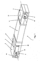
- Fig. 1 shows the ventilation device 1 consisting of the Dämmstoffkörpem 2, 3 and a arranged between this heat exchanger 4.
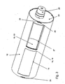
- the closing devices 5, 6 have essentially the structure shown in Fig. 2.
- An outer one Tube section 12 is designed in its inner diameter so that a inner pipe section 13 is longitudinally inserted therein.
- the outer one Pipe section 12 has four openings 14, 15, 16, 17, each one in pairs and along the central axis of the pipe section 12 is longitudinally displaced arranged in a plane opposite each other.
- the openings 14, 15 immediately adjacent as well as the openings 16 and 17th They are diametrically opposite each other with respect to the central axis.
- the outer one Tube section 12 forms with its matched inner diameter the storage of the inner pipe section 13, which in turn has four openings having. Two of the openings are relative to the axis of rotation forming longitudinal central axis of the pipe section laterally offset from each other while two further openings 20, 21 are angularly displaced towards the first pair of openings with respect to the axis of rotation directly are opposite. Furthermore, it is provided in the closing device 5, 6 that the longitudinal ends of the pipe sections 12, 13 with caps 22, 23 and 24th can be closed.
- the caps 22, 23 serve for the Closing the outer tube section 12 and are about a bayonet-type closure 25, 26 locked against each other.
- the bayonet-like Closure consists essentially of a T-shaped opening 25 in the lateral surface of the outer tube section 12, in the central T-leg is executed open-edge. In this open-edged opening, one of the cap 22, 23 protruding web 26 is inserted and after a Relative rotation are locked to the pipe section.
- the final fixation can od, for example by means of adhesive. Like. take place, but it can also possibly provided a snap-in connection become.
- the cap 22 is in any case releasably attached to the outer tube section 12 attached and contributes to the one frame 27, whose Outer dimensions substantially the inner dimensions of the inner Tube section 13 correspond. This will project the entire Cross sectional area of the inner tube portion of the frame 27th delimited, so that one mounted in the frame 27 - not here shown - filter element of which through the openings 14, 15, 16, 17th passed through volume flow can not be bypassed.
- the outer Section through a in the housing or the insulating body 2 to fixing pipe is formed.
- the outer pipe section 12 already by the Insulating body 2 and the housing is formed.
- the outer diameter of the inner pipe section 13 to form the Storage in a correspondingly dimensioned bore of the housing or of the insulating body 2, 3 can be introduced.
- the openings 14, 15, 16, 17 in the insulating body 2 or 3 to provide according to the arrangement of FIG.
- the actuator 28 for example, from an easy to related and therefore inexpensive electric motor consist of only one Running direction, for example, clockwise, must have. Of the Actuator 28 must to adjust an overlapping opening position of Openings 20, 21 with the openings 15, 17 from a position in which the Openings 18, 19 are in covering position with the openings 15, 16 are located be moved by 90 °.
- FIG. 3 on an enlarged scale, the closing device 5, 6 shown.
- the openings 25 are in the same way also on the actuator 28 opposite end of the outer Pipe section 12 provided.
- Embodiment of the locking device 5, 6 is in the - here only partially visible - frame 27 no filter element used, as well as in the Fig. 2 shown explosion model. Therefore, in the in Fig .. 3 illustrated embodiment, the position of the pipe sections 12, 13th visible, in which the diagonal openings 19, 18 are opened are opposite.
- FIG. 4 the basic structure of an insulating body 2 or 3 shown.
- the divided in a horizontal plane insulating body 3 has a bore 30 for receiving the locking device 5 and 6.
- 3 is also a longitudinal partition wall 31st provided, which - with the exception of the transverse bore 30 - a first ventilation duct 32 separates from a second ventilation duct 33.
- the Partition wall 31 is therefore also in that shown in FIG. 4 the rear portion which lies behind the bore 30, as will be explained later explained Fig. 5 is still clear.
- the section 34 are also transverse channels 35, 36th provided, of which in Fig. 4, only the channel 35 is visible. Furthermore, in the insulating body 2, 3 two adjacent receptacles 37, 38th provided for the impellers 7, 8 and 9, 10.
- the blower wheels 7, 8 or 9, 10 are mounted on a plate 41 in a flat trough 42 of the Insulating body 2, 3 is receivable.
- the plate 41 can still other plates made of steel o. ⁇ . Be attached, by means of the acoustic Behavior of the plate 41 can be changed.
- the insulating body 2, 3 is further with openings 43, 44, 45 and a protruding outlet 46th Mistake.
- the openings 43, 44, 45 and the outlet 46 are located laterally on the insulating body 2, 3 as is apparent from the Fig. 1.
- the receptacle 37 and the receptacle 38 essentially have the form a snail shell and thereby form spiral-shaped Ventilation housing for otherwise usable without housing Blower wheels 7, 8.
- the receptacle 37 empties into the protruding Outlet 46.
- the two Receivers 37, 38 each equipped with an impeller 7, 8 and 9, 10. It may, however, deviating from the illustration of FIG. 1 and 4 are provided be that only one of the shots 37 or 38 each with a Blower wheel 7 or 8 is provided. It is also envisaged that the Ventilation channel 32, for example, by inserting a plate 47 in the opening 44 is partially closed. This may be necessary if a Blower 7 is mounted in the receptacle 37, and also the recording 38 no fan 8 contains. If, however, no fan 8 in the recording 38 provided, the plate 47 is removed. This allows the Ventilation device 1 can also be used if only a small one Volume flow to be promoted.
- the recordings 37, 38 are in the Essentially designed so that the impellers 7, 8 and 9, 10 in one upper portion of the overall height of the insulating body 2, 3 is arranged are, so only a partial height of the insulating body 2, 3 make up.
- the Supply of the volume flow takes place in each case in a plane below the Blower wheels 7, 8 which, for example, by appropriate constrictions of Openings is reached, which open into the receptacles 37, 38.
- the principal Construction of the entire ventilation device 1 is based on FIGS. 5, 6 and 7 explained.
- a trough 48 is attached, which serves to hold any accumulating condensed water. This is in the flat pan led inward, to a frosting of the outside Ventilation grille to prevent.
- the insulating body 2, 3 are identical and between the center of the heat exchanger 4 record.
- the insulating body 2, 3 are each rotated by 180 ° to the heat exchanger 4 flanged.
- the Heat exchanger 4 is flowed through substantially C-shaped, so that the resulting in the longitudinal direction of the heat exchanger 4 ventilation ducts 50, 51, for connection to the ventilation channels 32, 33, respectively in the plane of the Inlet also have their outlet. This will be at a 180 ° rotation the insulating body 3 with respect to the insulating body 2 an assignment of the ventilation duct 32 in each case to one located in the heat exchanger 4 Ventilation channel 50 and 51 reached.
- FIGS. 5 to 7 the dividing wall 31 longitudinally through the entire insulation body 2 and 3 pulls with the exception of the visible in Fig. 4 bore 30 for receiving the Closing devices 5, 6.
- Figs. 5 to 7 are the respective closed openings 14, 15, 16, 17 with bold lines shown.
- a first ventilation position of the Lvidüngsvorraum 1 is provided that of the building exterior 52 sucked air through an inlet port 53 and by means of Adjusting device 6 guided along the designated ventilation channel 51 becomes.
- the volume flow is deflected by almost 180 ° and blown out through the outlet 46 on the inside of the building.
- Ventilation channel 50 located in the first ventilation channel 32nd the impeller body 3 located impeller (eg 7 or 10) on the on the outside of the building 52 located outlet 46 a volume flow of the building inside 54 can cause the building exterior 52.
- a heat exchange in the Ventilation duct 50 located exhaust air with the in the ventilation channel 51st available supply air possible.
- the ventilation position of the Closing devices 5, 6 therefore becomes an approximate diagonal Flow through the closing devices 5, 6 causes, possibly on the Outside of the building noise due to the changes in direction of the Volume flow can be attenuated. It also becomes clear that the Pipe sections 12, 13 for forming the closing devices 5, 6 in Essential along the conveying direction, yes from the Building outside 52 to the inside of the building 54 takes place or vice versa.
- the ventilation channels 32, 33 and 50, 51 here However, aligned substantially transversely to the conveying direction.
- the sixth Air is from the building inside 54 via the inlet opening 53 of the Insulating body 2 and via the inlet opening 55 of the insulating body. 5 aspirated and by means of the outlet 46 of the sound-absorbing body 2 again the building inside 54 blown out.
- the Closing devices 5, 6 are the by the closing devices 5, 6 and the insulating body 2, 3 formed ventilation ducts within the housing the ventilation device 1 except the area at the outlet 46th almost lying on one line, so do not cross over or over Deflections led.
- the outward openings of the Ventilation devices 1 are in this closed position of Closing devices 5, 6 closed so that outside air does not enter can.
- a recirculation mode of the ventilation device 1 can For example, be useful if within the ventilation ducts 50, 51 or 32, 33 additional measures for the treatment of the air provided become.
- Ventilation device 1 In the illustrated in Fig. 7 loading or venting position of Ventilation device 1 is provided that the heat exchanger. 4 facing ventilation ducts 32 via the locking devices 5, 6 opposite the building interior or building exterior 52, 54 are sealed off.
- a volume flow only within the insulating body 2, 3rd from the outside of the building to the inside of the building or from the Building inside 54 to the building exterior 52 arrive. It will also be there the volume flow within the ventilation device 1 several times by 90 ° deflected and flows through the closing devices 5, 6 substantially diagonal. Impact sound is therefore largely insulated.
- the Ventilation device 1 In this Switching position in which the heat exchanger 4 is not flowed through, are corresponding conditional by the heat exchanger 4 pressure losses switched off.
- the ventilation operation shown in Fig. 7 the Ventilation device 1 is therefore suitable for example at approximately same room temperatures inside and outside the building like for example prevailing in summer.
- Fig. 5 is including the Heat exchanger 4 a ventilation operation of the ventilation device. 1 adjustable (winter operation), while in Fig. 7 of the ventilation operation takes place when the heat exchanger 4 is switched off (summer mode).
- the Recirculation mode is a partial involvement of the Heat exchanger 4 is provided, but in this case no heat exchanging function exerts, since the ventilation duct 51 is not of a Volume flow at a different temperature than in the ventilation duct 50 flows through it.
- FIG. 8 shows the housing 60 of the ventilation device shown.
- the housing 60 consists essentially of about Connecting elements with each other coupled plates in a known manner from DE 44 22 862 A1 - to which reference is made in full - are composable. It is possible that the depth 61 but also the Length 62 of the housing 60 to structural conditions of the building be adjusted.
- the front plate 63 is substantially divided into three parts and consists of the end caps 64 and 65 and the profile 66. Center of the Profile 66 are the outlet 46 associated ventilation slots 67th provided while lying on the inside of the building Inlet openings 53, 55 through corresponding vent slot 68 in the End caps 64, 65 are connected to the building inside 54. additionally is on the end cap 64, a control panel 69 is provided with which the various ventilation and switching positions of the ventilation device. 1 can be adjusted.
- the insulating body 2 and 3 are preferably made of polystyrene, since these materials on the one hand ensure a relatively good thermal insulation and on the other hand contribute effectively to avoiding vibrations of the impellers.
Landscapes
- Engineering & Computer Science (AREA)
- Chemical & Material Sciences (AREA)
- Combustion & Propulsion (AREA)
- Mechanical Engineering (AREA)
- General Engineering & Computer Science (AREA)
- Seal Device For Vehicle (AREA)
- Air-Flow Control Members (AREA)
- Liquid Crystal (AREA)
- Iron Core Of Rotating Electric Machines (AREA)
- Massaging Devices (AREA)
- Ventilation (AREA)
Description
- Fig. 1
- eine Lüftungsvorrichtung ohne Gehäuse,
- Fig. 2
- eine Stellvorrichtung für eine Lüftungsvorrichtung in einer Explosionsdarstellung,
- Fig. 3
- eine Stellvorrichtung im montierten Zustand,
- Fig. 4
- einen Dämmkörper mit darin anbringbaren Komponenten der Lüftungsvorrichtung in einer Explosionsdarstellung,
- Fig. 5
- eine schematische Darstellung der Lüftungskanäle der Lüftungsvorrichtung in einer ersten Be- und Entlüftungsstellung (Winterstellung),
- Fig. 6
- eine Lüftungsvorrichtung nach Fig. 5 in einer zweiten Lüftungsstellung (Umluft),
- Fig. 7
- die Lüftungsvorrichtung nach Fig. 5 und 6 in einer dritten Lüftungsstellung (Sommerstellung) und
- Fig. 8
- die Lüftungsvorrichtung mit Gehäuse.
- 1
- Lüftungsvorrichtung
- 2
- Dämmstoffkörper
- 3
- Dämmstoffkörper
- 4
- Wärmetauscher
- 5
- Schließvorrichtung
- 6
- Schließvorrichtung
- 7
- Gebläserad
- 8
- Gebläserad
- 9
- Gebläserad
- 10
- Gebläserad
- 11
- -
- 12
- äußerer Rohrabschnitt
- 13
- innerer Rohrabschnitt
- 14
- Öffnung
- 15
- Öffnung
- 16
- Öffnung
- 17
- Öffnung
- 18
- Öffnung
- 19
- Öffnung
- 20
- Öffnung
- 21
- Öffnung
- 22
- Kappe
- 23
- Kappe
- 24
- Kappe
- 25
- Öffnung
- 26
- Steg
- 27
- Rahmen
- 28
- Stellantrieb
- 29 30
- Bohrung
- 31
- Trennwand
- 32
- Lüftungskanal
- 33
- Lüftungskanal
- 34
- Abschnitt
- 35
- Kanal
- 36
- Kanal
- 37
- Aufnahme
- 38
- Aufnahme
- 39 40 41
- Platte
- 42
- Mulde
- 43
- Öffnung
- 44
- Öffnung
- 45
- Öffnung
- 46
- Auslass
- 47
- Platte
- 50
- Lüftungskanal
- 51
- Lüftungskanal
- 52
- Gebäudeaußenseite
- 53
- Einlassöffnung
- 54
- Gebäudeinnenseite
- 55
- Einlassöffnung
- 60
- Gehäuse
- 61
- Tiefe
- 62
- Länge
- 63
- Frontplatte
- 64
- Endkappe
- 65
- Endkappe
- 66
- Profil
- 67
- Lüftungsschlitz
- 68
- Lüftungsschlitz
Claims (18)
- Lüftungsvorrichtung (1)
mit einem Gehäuse (60), welcher zwei Lüftungskanäle ausbildet, der über eine Schließvorrichtung (5, 6) zur Einstellung verschiedener Be- und Entlüftungsstellungen verfügt, wobei
die Schließvorrichtung (5, 6) aus zwei koaxial verlaufenden zylindrischen, ineinander liegenden Rohrabschnitten (12, 13) besteht, deren Mantelflächen mit über den Umfang verteilten, in Deckungslage bringbaren Öffnungen (14, 17; 18, 19; 20, 21) versehen sind, und der äußere Rohrabschnitt (12) die Lagerung des darin drehbeweglich aufgenommenen inneren Rohrabschnitts (12) bildet.
dadurch gekennzeichnet,
das in dem Gehäuse (60) ein Wärmetauscher (4) der zwei Lüftungskanäle ausbildet, zwischen zwei die Schließvorrichtung (5, 6) und eine Zwangslüftungsvorrichtung aufnehmenden identischen, um 180° zueinander gedreht angeordneten Dämmstoffkörpem (2, 3) liegt, die jeweils zwei Lüftungskanäle (32, 33) bereitstellten. - Lüftungsvorrichtung nach Anspruch 1,
dadurch gekennzeichnet, dass der äußere Rohrabschnitt (12) durch ein in dem Gehäuse (60) zu befestigendes Rohr gebildet wird. - Lüftungsvorrichtung nach einem der Ansprüche 1 bis 2,
dadurch gekennzeichnet, dass die Achse der Rohrabschnitte (12, 13) im wesentlichen längs der Förderrichtung liegt, wobei die Lüftungskanäle (32, 33, 50, 51) innerhalb des Gehäuses (60) im wesentlichen quer dazu verläuft. - Lüftungsvorrichtung nach einem der Ansprüche 2 bis 3,
dadurch gekennzeichnet, dass der äußere Rohrabschnitt (12) in dem Dämmstoffkörper (2, 3) aufgenommen ist. - Lüftungsvorrichtung nach einem der Ansprüche 1 bis 4,
dadurch gekennzeichnet, dass die Längsenden des äußeren Rohrabschnitts (12) mit Kappen (22, 23) verschlossen sind, die mittels bajonettartiger Verschlüsse (25, 26) befestigt sind. - Lüftungsvorrichtung nach einem der Ansprüche 1 bis 5,
dadurch gekennzeichnet, dass in den Rohrabschnitten (12, 13) ein Filterelement aufgenommen ist. - Lüftungsvorrichtung nach Anspruch 6,
dadurch gekennzeichnet, dass das Filterelement an der Kappe (22) befestigt ist. - Lüftungsvorrichtung nach Anspruch 7,
dadurch gekennzeichnet, dass die das Filterelement tragende Kappe (22) zur Gebäudeinnenseite (54) weist - Lüftungsvorrichtung nach einem der Ansprüche 5 bis 8,
dadurch gekennzeichnet, dass die an dem inneren Rohrabschnitt (13) endseitig eine drehfest mit dem Rohrabschnitt (13) verbundene Kappe (24) mit einem Stellantrieb (28) verbunden ist. - Lüftungsvorrichtung nach Anspruch 9,
dadurch gekennzeichnet, dass der Stellantrieb (28) an der Kappe (23) des äußeren Rohrabschnitts (12) befestigt ist. - Lüftungsvorrichtung nach einem der Ansprüche 9 oder 10,
dadurch gekennzeichnet, dass der Stellantrieb (28) elektrisch betrieben ist und auf den Kappen (23, 24) Hallsensoren zur Kennzeichnung der Stellung des Rohrabschnitts (13) angebracht sind. - Lüftungsvorrichtung nach Anspruch 1,
dadurch gekennzeichnet, dass der äußere Rohrabschnitt (12) vier Öffnungen (14, 15, 16, 17) aufweist, die sich paarweise und längs der Drehachse verschoben gegenüberliegen. - Lüftungsvorrichtung nach einem der Ansprüche 1 oder 12,
dadurch gekennzeichnet, dass der innere Rohrabschnitt (13) vier Öffnungen (18, 19, 20, 21) aufweist, von denen zwei (18, 19) bezüglich der Drehachse einander längsverschoben und zwei Öffnungen (20, 21) senkrecht zur Drehachse gegenüberliegen. - Lüftungsvorrichtung nach Anspruch 1,
dadurch gekennzeichnet, dass der Wärmetauscher (4) im wesentlichen C-förmig durchströmt wird. - Lüftungsvorrichtung nach einem der Ansprüche 1 bis 14,
dadurch gekennzeichnet, dass die Dämmstoffkörper (2, 3), mit Ausnahme der querverlaufenden Bohrung (30) zur Aufnahme der Rohrabschnitte (12, 13), eine längsverlaufende Trennwand (31) aufweisen. - Lüftungsvorrichtung nach Anspruch 15,
dadurch gekennzeichnet, dass der Dämmstoffkörper (2, 3) zwei nebeneinanderliegende Aufnahmen (37, 38) für Gebläseräder (7, 8; 9, 10) aufweist, die in einer flachen Mulde (42) des Dämmstoffkörpers (2, 3) liegen, wobei die Gebläseräder auf einer in der Mulde (42) eingebetteten Platte (41) befestigt sind. - Lüftungsvorrichtung nach einem der Ansprüche 1 bis 16,
dadurch gekennzeichnet, dass eine der Aufnahmen (37) für die Gebläseräder (7, 8; 9, 10) in einen vorragenden querverlaufenden Auslass (46) mündet. - Lüftungsvorrichtung nach Anspruch 17,
dadurch gekennzeichnet, dass Dämmstoffkörper (2, 3) und Wärmetauscher (4) in dem Gehäuse (60) angeordnet sind und dass das Gehäuse (60) endseitig und mittig angebrachte Lüftungsschlitze (67, 68) aufweist, wobei die mittig angebrachten Lüftungsschlitze (67) dem Auslass (46) zugeordnet sind.
Applications Claiming Priority (5)
| Application Number | Priority Date | Filing Date | Title |
|---|---|---|---|
| DE10013689A DE10013689A1 (de) | 2000-03-21 | 2000-03-21 | Lüftungsvorrichtung |
| DE10013689 | 2000-03-21 | ||
| DE10013691 | 2000-03-21 | ||
| DE10013691A DE10013691A1 (de) | 2000-03-21 | 2000-03-21 | Lüftungsvorrichtung |
| PCT/EP2001/000998 WO2001071262A1 (de) | 2000-03-21 | 2001-01-31 | Lüftungsvorrichtung |
Publications (2)
| Publication Number | Publication Date |
|---|---|
| EP1266180A1 EP1266180A1 (de) | 2002-12-18 |
| EP1266180B1 true EP1266180B1 (de) | 2005-10-05 |
Family
ID=26004919
Family Applications (1)
| Application Number | Title | Priority Date | Filing Date |
|---|---|---|---|
| EP01903683A Expired - Lifetime EP1266180B1 (de) | 2000-03-21 | 2001-01-31 | Lüftungsvorrichtung |
Country Status (6)
| Country | Link |
|---|---|
| EP (1) | EP1266180B1 (de) |
| AT (1) | ATE306057T1 (de) |
| AU (1) | AU2001231695A1 (de) |
| DE (1) | DE50107615D1 (de) |
| DK (1) | DK1266180T3 (de) |
| WO (1) | WO2001071262A1 (de) |
Families Citing this family (1)
| Publication number | Priority date | Publication date | Assignee | Title |
|---|---|---|---|---|
| CN112797234A (zh) * | 2021-01-29 | 2021-05-14 | 惠风(浙江)环境科技有限公司 | 一种自带保温的通风管 |
Family Cites Families (15)
| Publication number | Priority date | Publication date | Assignee | Title |
|---|---|---|---|---|
| US3659515A (en) * | 1970-09-08 | 1972-05-02 | Ford Motor Co | Apparatus for delivering moving air |
| DE3208392A1 (de) * | 1982-03-09 | 1983-09-22 | Ziehl-Abegg GmbH & Co KG, 7119 Künzelsau | Lueftungsgeraet zum be- und entlueften von raeumen |
| NL8901594A (nl) | 1989-06-23 | 1991-01-16 | Giemeta Luvema Bv | Ventilatie-inrichting. |
| JPH0424466A (ja) * | 1990-05-16 | 1992-01-28 | Mitsubishi Electric Corp | 風路切換用シャッタ装置 |
| US5062352A (en) * | 1990-07-16 | 1991-11-05 | General Motors Corporation | Motor vehicle heating, ventilating and air conditioning system with combined mode/temperature door |
| JP2716645B2 (ja) * | 1993-04-08 | 1998-02-18 | 鹿島建設株式会社 | 給排気口切替えユニット |
| DE9313426U1 (de) | 1993-09-07 | 1993-10-14 | Siegenia-Frank Kg, 57074 Siegen | Lüftungsvorrichtung für Räume |
| US5399120A (en) * | 1993-11-05 | 1995-03-21 | General Motors Corporation | Air conditioning system control valve |
| SE505423C2 (sv) * | 1993-12-30 | 1997-08-25 | Saab Automobile | Luftfördelningsanordning till ett ventilationssystem för fordon |
| DE19539811C2 (de) * | 1995-10-26 | 2000-02-24 | Altura Leiden Holding | Lüftungsvorrichtung |
| GB2308439B (en) * | 1995-12-21 | 1999-03-10 | Rover Group | A vehicle and an air flow control valve therefor |
| DE29611515U1 (de) | 1996-07-02 | 1996-09-05 | Siegenia-Frank Kg, 57074 Siegen | Umluft-Betriebsvorrichtung für ein Zwangslüftungsgerät |
| DE19637564C1 (de) * | 1996-09-14 | 1997-11-20 | Konvekta Ag | Luftverteilerkasten |
| DE29704633U1 (de) | 1997-03-14 | 1997-06-26 | Hahn, Ulf, 34637 Schrecksbach | Einrichtung zur Rückgewinnung von Wärmeenergie |
| JPH11118236A (ja) * | 1997-10-17 | 1999-04-30 | Nippon Alum Co Ltd | 建造物用換気装置 |
-
2001
- 2001-01-31 DK DK01903683T patent/DK1266180T3/da active
- 2001-01-31 AT AT01903683T patent/ATE306057T1/de not_active IP Right Cessation
- 2001-01-31 DE DE50107615T patent/DE50107615D1/de not_active Expired - Fee Related
- 2001-01-31 EP EP01903683A patent/EP1266180B1/de not_active Expired - Lifetime
- 2001-01-31 WO PCT/EP2001/000998 patent/WO2001071262A1/de not_active Ceased
- 2001-01-31 AU AU2001231695A patent/AU2001231695A1/en not_active Abandoned
Also Published As
| Publication number | Publication date |
|---|---|
| WO2001071262A1 (de) | 2001-09-27 |
| EP1266180A1 (de) | 2002-12-18 |
| ATE306057T1 (de) | 2005-10-15 |
| AU2001231695A1 (en) | 2001-10-03 |
| DK1266180T3 (da) | 2006-02-20 |
| DE50107615D1 (de) | 2006-02-16 |
Similar Documents
| Publication | Publication Date | Title |
|---|---|---|
| EP0740617B1 (de) | Heizungs- und/oder klimaeinrichtung | |
| AT394773B (de) | Ventilatoreinheit mit waermewiedergewinnung, vorzugsweise fuer die anordnung in einer aussenwanddes zu belueftenden raumes | |
| DE102008058817A1 (de) | Luft-Luft-Wärmetauscher | |
| DE69016674T2 (de) | Wärmerückgewinnender ventilator. | |
| DE6610779U (de) | Raumventilator mit gleichzeitiger foerderung von aussenluft in den innenraum und von innenraumluft nach aussen, insbesondere mit zwischenverschluss. | |
| DE3017431C2 (de) | Lüftungsvorrichtung für Räume mit zwei getrennten Strömungswegen zur Be- und Entlüftung | |
| DE102005035712A1 (de) | Kompaktlüftungsgerät mit Wärmerückgewinnung | |
| DE202011050995U1 (de) | Bodenwanne zum Verbinden eines Dachaufbau-Kühlgerätes mit dem Dach eines Schaltschrankes | |
| DE4143036A1 (de) | Belueftungseinrichtung fuer raeume | |
| DE2232482C2 (de) | Lüftungsanlage | |
| DE3347028A1 (de) | Fenster | |
| DE60204223T2 (de) | Lüftungsanordnung zum abführen von luft | |
| DE10013689A1 (de) | Lüftungsvorrichtung | |
| DE202021103103U1 (de) | Lüftungsvorrichtung | |
| DE9301812U1 (de) | Entlüftungs- und Belüftungsanlage mit einem Wärmespeicher | |
| DE19753617B4 (de) | Vorrichtung zur Heizung, Belüftung und/oder Klimatisierung, insbesondere für den Fahrgastraum eines Kraftfahrzeugs | |
| DE10106672B4 (de) | Längsschneideinrichtung | |
| DE19844578A1 (de) | Belüftungs- und Entlüftungsanlage | |
| WO2013041224A2 (de) | Blendrahmen eines fensters mit integrierter lüftungseinrichtung und lüftungseinrichtung hierfür | |
| DE10002023B4 (de) | Klappeneinrichtung in einer Heizungs- oder Klimaanlage eines Kraftfahrzeugs | |
| DE3014754A1 (de) | Geraet zum gleichzeitigen be- und entlueften von raeumen | |
| EP1266180A1 (de) | Lüftungsvorrichtung | |
| DE10119591A1 (de) | Kühlanlage für Kraftfahrzeuge | |
| DE2013455A1 (de) | Belüftungsvorrichtung mit Wärmeaustauscher | |
| DE10013691A1 (de) | Lüftungsvorrichtung |
Legal Events
| Date | Code | Title | Description |
|---|---|---|---|
| PUAI | Public reference made under article 153(3) epc to a published international application that has entered the european phase |
Free format text: ORIGINAL CODE: 0009012 |
|
| 17P | Request for examination filed |
Effective date: 20020706 |
|
| AK | Designated contracting states |
Kind code of ref document: A1 Designated state(s): AT BE CH CY DE DK ES FI FR GB GR IE IT LI LU MC NL PT SE TR |
|
| AX | Request for extension of the european patent |
Free format text: AL;LT;LV;MK;RO;SI |
|
| RAP1 | Party data changed (applicant data changed or rights of an application transferred) |
Owner name: SIEGENIA-AUBI KG |
|
| RAP1 | Party data changed (applicant data changed or rights of an application transferred) |
Owner name: SIEGENIA-AUBI KG |
|
| RAP1 | Party data changed (applicant data changed or rights of an application transferred) |
Owner name: SIEGENIA-AUBI KG |
|
| 17Q | First examination report despatched |
Effective date: 20040906 |
|
| GRAP | Despatch of communication of intention to grant a patent |
Free format text: ORIGINAL CODE: EPIDOSNIGR1 |
|
| GRAS | Grant fee paid |
Free format text: ORIGINAL CODE: EPIDOSNIGR3 |
|
| GRAA | (expected) grant |
Free format text: ORIGINAL CODE: 0009210 |
|
| AK | Designated contracting states |
Kind code of ref document: B1 Designated state(s): AT BE CH CY DE DK ES FI FR GB GR IE IT LI LU MC NL PT SE TR |
|
| PG25 | Lapsed in a contracting state [announced via postgrant information from national office to epo] |
Ref country code: IT Free format text: LAPSE BECAUSE OF FAILURE TO SUBMIT A TRANSLATION OF THE DESCRIPTION OR TO PAY THE FEE WITHIN THE PRESCRIBED TIME-LIMIT;WARNING: LAPSES OF ITALIAN PATENTS WITH EFFECTIVE DATE BEFORE 2007 MAY HAVE OCCURRED AT ANY TIME BEFORE 2007. THE CORRECT EFFECTIVE DATE MAY BE DIFFERENT FROM THE ONE RECORDED. Effective date: 20051005 |
|
| REG | Reference to a national code |
Ref country code: GB Ref legal event code: FG4D Free format text: NOT ENGLISH |
|
| REG | Reference to a national code |
Ref country code: SE Ref legal event code: TRGR |
|
| REG | Reference to a national code |
Ref country code: CH Ref legal event code: EP Ref country code: CH Ref legal event code: NV Representative=s name: PA ALDO ROEMPLER |
|
| GBT | Gb: translation of ep patent filed (gb section 77(6)(a)/1977) |
Effective date: 20051005 |
|
| REG | Reference to a national code |
Ref country code: IE Ref legal event code: FG4D Free format text: LANGUAGE OF EP DOCUMENT: GERMAN |
|
| PGFP | Annual fee paid to national office [announced via postgrant information from national office to epo] |
Ref country code: GB Payment date: 20051222 Year of fee payment: 6 |
|
| PG25 | Lapsed in a contracting state [announced via postgrant information from national office to epo] |
Ref country code: GR Free format text: LAPSE BECAUSE OF FAILURE TO SUBMIT A TRANSLATION OF THE DESCRIPTION OR TO PAY THE FEE WITHIN THE PRESCRIBED TIME-LIMIT Effective date: 20060105 |
|
| PG25 | Lapsed in a contracting state [announced via postgrant information from national office to epo] |
Ref country code: ES Free format text: LAPSE BECAUSE OF FAILURE TO SUBMIT A TRANSLATION OF THE DESCRIPTION OR TO PAY THE FEE WITHIN THE PRESCRIBED TIME-LIMIT Effective date: 20060116 |
|
| PGFP | Annual fee paid to national office [announced via postgrant information from national office to epo] |
Ref country code: AT Payment date: 20060120 Year of fee payment: 6 Ref country code: FR Payment date: 20060120 Year of fee payment: 6 Ref country code: SE Payment date: 20060120 Year of fee payment: 6 |
|
| PGFP | Annual fee paid to national office [announced via postgrant information from national office to epo] |
Ref country code: IE Payment date: 20060122 Year of fee payment: 6 |
|
| PGFP | Annual fee paid to national office [announced via postgrant information from national office to epo] |
Ref country code: BE Payment date: 20060123 Year of fee payment: 6 Ref country code: DK Payment date: 20060123 Year of fee payment: 6 Ref country code: FI Payment date: 20060123 Year of fee payment: 6 |
|
| PGFP | Annual fee paid to national office [announced via postgrant information from national office to epo] |
Ref country code: CH Payment date: 20060124 Year of fee payment: 6 Ref country code: NL Payment date: 20060124 Year of fee payment: 6 |
|
| PG25 | Lapsed in a contracting state [announced via postgrant information from national office to epo] |
Ref country code: LU Free format text: LAPSE BECAUSE OF NON-PAYMENT OF DUE FEES Effective date: 20060131 Ref country code: MC Free format text: LAPSE BECAUSE OF NON-PAYMENT OF DUE FEES Effective date: 20060131 |
|
| PGFP | Annual fee paid to national office [announced via postgrant information from national office to epo] |
Ref country code: DE Payment date: 20060131 Year of fee payment: 6 |
|
| REF | Corresponds to: |
Ref document number: 50107615 Country of ref document: DE Date of ref document: 20060216 Kind code of ref document: P |
|
| REG | Reference to a national code |
Ref country code: DK Ref legal event code: T3 |
|
| PG25 | Lapsed in a contracting state [announced via postgrant information from national office to epo] |
Ref country code: PT Free format text: LAPSE BECAUSE OF FAILURE TO SUBMIT A TRANSLATION OF THE DESCRIPTION OR TO PAY THE FEE WITHIN THE PRESCRIBED TIME-LIMIT Effective date: 20060306 |
|
| ET | Fr: translation filed | ||
| PLBE | No opposition filed within time limit |
Free format text: ORIGINAL CODE: 0009261 |
|
| STAA | Information on the status of an ep patent application or granted ep patent |
Free format text: STATUS: NO OPPOSITION FILED WITHIN TIME LIMIT |
|
| 26N | No opposition filed |
Effective date: 20060706 |
|
| PG25 | Lapsed in a contracting state [announced via postgrant information from national office to epo] |
Ref country code: LI Free format text: LAPSE BECAUSE OF NON-PAYMENT OF DUE FEES Effective date: 20070131 Ref country code: FI Free format text: LAPSE BECAUSE OF NON-PAYMENT OF DUE FEES Effective date: 20070131 Ref country code: CH Free format text: LAPSE BECAUSE OF NON-PAYMENT OF DUE FEES Effective date: 20070131 |
|
| PG25 | Lapsed in a contracting state [announced via postgrant information from national office to epo] |
Ref country code: SE Free format text: LAPSE BECAUSE OF NON-PAYMENT OF DUE FEES Effective date: 20070201 |
|
| PG25 | Lapsed in a contracting state [announced via postgrant information from national office to epo] |
Ref country code: DE Free format text: LAPSE BECAUSE OF NON-PAYMENT OF DUE FEES Effective date: 20070801 |
|
| REG | Reference to a national code |
Ref country code: CH Ref legal event code: PL |
|
| GBPC | Gb: european patent ceased through non-payment of renewal fee |
Effective date: 20070131 |
|
| NLV4 | Nl: lapsed or anulled due to non-payment of the annual fee |
Effective date: 20070801 |
|
| REG | Reference to a national code |
Ref country code: DK Ref legal event code: EBP |
|
| EUG | Se: european patent has lapsed | ||
| REG | Reference to a national code |
Ref country code: IE Ref legal event code: MM4A |
|
| REG | Reference to a national code |
Ref country code: FR Ref legal event code: ST Effective date: 20070930 |
|
| PG25 | Lapsed in a contracting state [announced via postgrant information from national office to epo] |
Ref country code: GB Free format text: LAPSE BECAUSE OF NON-PAYMENT OF DUE FEES Effective date: 20070131 Ref country code: AT Free format text: LAPSE BECAUSE OF NON-PAYMENT OF DUE FEES Effective date: 20070131 |
|
| BERE | Be: lapsed |
Owner name: *SIEGENIA-AUBI K.G. Effective date: 20070131 |
|
| PG25 | Lapsed in a contracting state [announced via postgrant information from national office to epo] |
Ref country code: BE Free format text: LAPSE BECAUSE OF NON-PAYMENT OF DUE FEES Effective date: 20070131 |
|
| PG25 | Lapsed in a contracting state [announced via postgrant information from national office to epo] |
Ref country code: NL Free format text: LAPSE BECAUSE OF NON-PAYMENT OF DUE FEES Effective date: 20070801 Ref country code: IE Free format text: LAPSE BECAUSE OF NON-PAYMENT OF DUE FEES Effective date: 20070131 Ref country code: DK Free format text: LAPSE BECAUSE OF NON-PAYMENT OF DUE FEES Effective date: 20070131 |
|
| PG25 | Lapsed in a contracting state [announced via postgrant information from national office to epo] |
Ref country code: FR Free format text: LAPSE BECAUSE OF NON-PAYMENT OF DUE FEES Effective date: 20070131 |
|
| PG25 | Lapsed in a contracting state [announced via postgrant information from national office to epo] |
Ref country code: TR Free format text: LAPSE BECAUSE OF FAILURE TO SUBMIT A TRANSLATION OF THE DESCRIPTION OR TO PAY THE FEE WITHIN THE PRESCRIBED TIME-LIMIT Effective date: 20051005 |
|
| PG25 | Lapsed in a contracting state [announced via postgrant information from national office to epo] |
Ref country code: CY Free format text: LAPSE BECAUSE OF FAILURE TO SUBMIT A TRANSLATION OF THE DESCRIPTION OR TO PAY THE FEE WITHIN THE PRESCRIBED TIME-LIMIT Effective date: 20051005 |