EP1265056A1 - Befestigungssystem für ein abnehmbares modul in einem Kreis mit Schiebeverriegelung - Google Patents
Befestigungssystem für ein abnehmbares modul in einem Kreis mit Schiebeverriegelung Download PDFInfo
- Publication number
- EP1265056A1 EP1265056A1 EP02291265A EP02291265A EP1265056A1 EP 1265056 A1 EP1265056 A1 EP 1265056A1 EP 02291265 A EP02291265 A EP 02291265A EP 02291265 A EP02291265 A EP 02291265A EP 1265056 A1 EP1265056 A1 EP 1265056A1
- Authority
- EP
- European Patent Office
- Prior art keywords
- nipple
- nipples
- drawer
- support
- upstream
- Prior art date
- Legal status (The legal status is an assumption and is not a legal conclusion. Google has not performed a legal analysis and makes no representation as to the accuracy of the status listed.)
- Withdrawn
Links
Images


Classifications
-
- E—FIXED CONSTRUCTIONS
- E03—WATER SUPPLY; SEWERAGE
- E03B—INSTALLATIONS OR METHODS FOR OBTAINING, COLLECTING, OR DISTRIBUTING WATER
- E03B7/00—Water main or service pipe systems
- E03B7/07—Arrangement of devices, e.g. filters, flow controls, measuring devices, siphons, valves, in the pipe systems
- E03B7/072—Arrangement of flowmeters
-
- E—FIXED CONSTRUCTIONS
- E03—WATER SUPPLY; SEWERAGE
- E03B—INSTALLATIONS OR METHODS FOR OBTAINING, COLLECTING, OR DISTRIBUTING WATER
- E03B7/00—Water main or service pipe systems
- E03B7/09—Component parts or accessories
- E03B7/095—Component holders or housings, e.g. boundary boxes
-
- G—PHYSICS
- G01—MEASURING; TESTING
- G01F—MEASURING VOLUME, VOLUME FLOW, MASS FLOW OR LIQUID LEVEL; METERING BY VOLUME
- G01F15/00—Details of, or accessories for, apparatus of groups G01F1/00 - G01F13/00 insofar as such details or appliances are not adapted to particular types of such apparatus
- G01F15/18—Supports or connecting means for meters
- G01F15/185—Connecting means, e.g. bypass conduits
Definitions
- the present invention relates to a system for fixing of a removable module on circuits with a lock from the module to the circuits by a guillotine.
- She is particularly, but not limited to, suitable for counting sets removable on fluidic or electrical or mixed circuits. She can be implemented in fluid distribution networks and more particularly water to subscribers.
- the water distribution metering sets are devices intended to count the water consumed by a subscriber and are generally fitted with fittings necessary for the correct use of the circuit, namely a tap before counter, a non-return valve and the counter.
- the metering systems can be installed in homes, they are then generally in the open air and relatively accessible easy, or outside and, then, in general, in a look or a counting terminal buried in whole or in part in the ground in order to protect from the effects of frost where they are more difficult to access.
- the tap before meter is intended for the interruption of water either by the subscriber in the event of a prolonged absence, a leak in the circuit etc., or by the water distributor when replacing the meter or intervention on the valve after meter.
- the tap before the meter is only used by the distributor for replacing the counter out of water.
- the non-return valve is intended to prevent backflow of water from the circuit subscriber to the distribution circuit during a pressure drop relative of the network.
- the counting assembly can also have a tap after meter.
- all of counting consists of a rail or support stiffening the assembly and connected to the inlet or upstream and outlet or downstream ends of the counting unit and the linked fittings by systems with rotating nuts assembled on threads.
- the seals are generally made by flat seals, positioned between the spans of the members to be assembled and compressed by tightening. It should be noted that this type of flat seal requires replacement during each disassembly.
- Interventions are, in order of frequency, meter reading, meter replacement, check or replace the valve, replace the tap before meter. If these interventions are made out of water thanks to the closing of the tap before the meter, obviously not the same for the replacement of the front meter tap which requires a water cut upstream of the assembly count.
- a modular implementation has therefore been proposed as in applications FR 2 798 182 and FR 2 800 401 concerning the water distribution and which describe rail systems of removable counters with hanging device that allow solve some of the disadvantages mentioned above because it just work on locked modules whose exchange is relatively fast.
- the whole and the means of locks described therein allow time reduction intervention and water shutdown by upstream and downstream shutters is automatically controlled by removal of the removable module.
- the system is relatively complex and made up of a large number of components and seals, which implies a cost price higher and increases the risk of failure.
- intervention repair or replacement is delicate and requires a shutdown upstream water.
- the object of the invention is therefore to propose a system which solves these connection problems while benefiting from the advantages of using a removable module.
- the invention therefore relates to a system of fixing on a base of a removable module comprising at least two ends on nipples ending circuits, the base comprising a support holding said nipples, the module being removably attached to the base by means of mobile attachment to at least one locking position and one release position, end and corresponding nipple interpenetrating.
- interpenetration means that the nipple comes into covering the end or that, conversely, the end comes covering the nipple.
- the mobile fixing means is a guillotine comprising a drawer movable in translation by at least one lateral edge in a support guide, the drawer comprising at least interlocking nipple and end locking edge, the locking edge engaging in a through groove and a groove in alignments in the thickness of the end and the nipple to lock them together in the locked position.
- the module locking means are therefore simplified by implementing a guillotine mounting acting directly on the ends to be connected which eliminates the obligation of stiffening by rail or other of the module removable and which may optionally include a means of Keying.
- the invention is also applicable to a system whose module is a removable counting assembly with fluid circuit and comprising on the one hand a base with a support, a nipple of upstream connection, a downstream connection nipple and, on the other hand, the counting assembly, the two nipples being held by the support, the counting assembly by a upstream end and a downstream end being connected in a way waterproof on the upstream nipple and the downstream nipple respectively, the counting assembly being further detachably attached on the base by means of mobile attachment to at least one locking position and a release position, the ends and the nipples interpenetrating.
- the mobile fixing means is therefore a guillotine comprising a drawer or plate movable in translation by at least a side edge in a support guide, the drawer comprising at minus a locking edge engaging a groove opening and a groove in alignment in the thickness of end and nipple to lock them together in position lock.
- counting set is not limiting and we considers whether or not the removable module of the system has a actual counting means and whether or not it allows circulation of a fluid. Indeed, the invention is also applicable to a system forming a "fluid lock" closing and blocking the nipple holes to prevent circulation of fluid and a possible attempted fraud by pricking. Likewise, the term counting gaze is not limiting and the invention can be implemented in the form of a manhole, a terminal or simply free in a cellar or other. The system can therefore take place in a manhole type housing intended to be buried, in a terminal (above ground) or in any enclosure or housing may have space constraints.
- the present invention is particularly indicated in the part of maintenance operations, it is also applicable in a more general connection of circuits to a module which can as well a counting set as everything another module, for example a sanitary unit such as a sink or bidet ... with connection of hot and cold water inlets and wastewater outlet possibly associated with connections electrical including earth.
- the module can also be a chemical or physical treatment unit for a fluid that can also require electrical connections including a connection to at least two circuits.
- the fluid term therefore covers a liquid such as water, as well as gas or electricity.
- the invention may also include a number of nipples different from the number of ends of the removable module, the module can be locked in different positions and well connect different nipples based on these positions.
- the number of elements or components is reduces as well as the number of seals or insulations which reduces risks of default. Handling is simplified and reduced in number for the implementation of the system. The efforts to be applied are also reduced and specific tools are not more essential to assemble some of the elements. The cost cost of the system is reduced overall by the economy obtained concerning the hardware system as such and its implementation implemented by reducing the duration of intervention in particular.
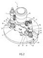
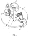
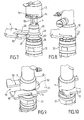
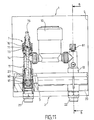
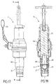
- a removable module 1 comprising a counting assembly 10 is separated from a base 2 comprising a support 20 now an upstream nipple 21 and a downstream nipple 22.
- the counting assembly includes in the direction of flow normal fluid, upstream end 11, front valve counter 7 with its tap body 70 and its means of command 75 which is a maneuver square, a counter, a first purge 81, an internal check valve 80, a second purge 82 and a downstream end 12.
- These elements are of preferably connected by a quick connection means to ring notching allowing tightening without specific tools.
- one or more of the items mentioned are omitted, for example one of the purges, or others added.
- the base 2 does not has no means of adaptation to the spacing of the ends 11, 12 of the counting assembly 10
- the latter then comprises an adapter ring so that it is the counting assembly which can be adapted to the spacing of the base nipples.
- the upstream nipple 21 and downstream nipple 22 have shutters 6 which are normally closed when the counting assembly is separate from the base.
- a elastic means, spring for example can act on a movable ball or the ball be in a lower density material than the fluid.
- a fixed control finger 83 allows the opening of the shutter member when all of metering 10 is installed on base 2 and therefore the purge of the circuit downstream by purge 82.
- the removable counting assembly 10 therefore comprises a tap before counter 7 whose shutter member is the shutter upstream.
- the downstream shutter can be controlled by a pusher or finger 83 which causes it to open when the module is put in place.
- a guillotine locking means comprising a drawer 3 of the plate or slide type that can be mobilized in translation in guides 29 of the support is shown here disassembled.
- the drawer 3 comprises lugs 34 which can circulate in the guides 29 and the support includes notches 24 intended to allow the placement of the drawer 3 in the guides 29 of the support.
- the drawer has at its two ends grooves 31 with a two opposite opposite locking edges 30 and opposite two to of them.
- the groove 31 on the upstream side opens towards the inside of the drawer in a hole 32 of larger diameter through which the upstream end 11 can pass but not the downstream end 12 which has a flange 14 whose diameter is greater than the orifice 32 thus forming a key for the direction of positioning of counting unit 10.
- valve bodies including upstream and downstream ends are generally made by molding or stamping of copper metals, then machined. In order to optimize methods of production, they may consist of raw parts identical, differentiated by their machining of the valve body before counter, the flange will be machined to remove the Keyed.
- the coding of the sense of positioning of the removable module 1 is obtained by setting work of a rough circular boss or flange 14, machined on one from both ends. So the introduction of the set of counting 10 backwards is impossible, facilitating handling and prohibiting fraud.
- other means are being considered coding.
- the keying is obtained by the different shape of nipple / end connections upstream side and side downstream. We make, for example, a system in which the nipple upstream is female, the upstream end being male, and the downstream nipple is male, the downstream end being female, or vice versa.
- the invention can also be implemented with a removable module which is not functionally oriented. In this case, the keying device (s) are omitted.
- the drawer 3 further comprises a notch 33 intended for receive an operating finger 40 from an operating key 4 positioning in a blind opening 25 of the support.
- the locking edges are intended to be housed in through grooves 13 with ends 11 and 12 and grooves 23 nipples 21, 22 as shown in Figures 7 to 11 to obtain the locking of the assembly 10 on the base 2.
- the bodies of the valves before meter and after counter which are made in foundry or die forging of copper metal have side lights or grooves through outlets 13, obtainable directly by molding, without resumption of the part in machining.
- These grooves 13 are intended to come into alignment alignment with grooves 23 located on the nipples and allow the passage of locking edges 30 of the slide or drawer 3 which ensures by its longitudinal displacement the locking and unlocking of the counting assembly.
- the drawer 3 therefore has an orifice oblong 32 opening outwards through a groove 31 at one first end and a single groove 31 at one second end.
- the counting assembly is introduced when the circular orifice of the drawer 3 is concentric with the counting axis and blocking is achieved when the grooves 13 by their edges of locking 30 cooperate with the grooves 23 of the nipples.
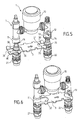
- Figures 5 and 6 in which the support 20 has not been shown as Figures 7 to 10 allow better view the guillotine assembly and the relationships between drawer 3, the ends 11, 12 with their through grooves 13 and the nipples 21, 22 with their grooves 23.
- the gripping means 63 of the shutter member 6 and the external thread 28 of the nipple The obturation organ is in screwed effect and the grip means allows tightening and loosening.
- the external thread 28 allows the mounting of a tube airlock for replacement of the shutter member under fluid charge.
- the nipples 21 and 22 further include flat areas allowing their immobilization in rotation in the support 20.
- the arrangement of locking edges may be different and for example only one edge by groove and on the axis of symmetry of the drawer.
- the engagement being made only on one side of the nipples and ends, the locking is asymmetrical.
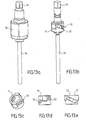
- FIG 11 in relation to Figures 13a, 13b, 13c, 13d, 13th, detail the tap 7 before the counter which controls the organ shutter 6 upstream.
- the tap 7 comprises a body 70 crossed by a push rod 74 with an operating means 75 to square head type panels.
- the body 70 has internally a cam 71 immobilized in the body and concentric with the rod thrust 74.
- the cam 71 has two symmetrical grooves 72 in which a pin 73 passes through the rod of thrust 74.
- the operating means 75 is operational on a quarter turn.
- the cam is a piece preferably made of plastic, injected for example.
- Each of the grooves 72 has three profile areas different to make the torque substantially constant at provide to open the shutter and to provide indexing of limit switch.
- the first zone of low slope corresponds to the start of the opening of the shutter member 6 when the pressure differential between the faces of said member 6 is the most tall. Once the opening has occurred, the pressures tend to equalize on either side of organ 6, which corresponds to the second zone of greater slope.
- the third reverse slope area is a way to secure the open position.
- the groove or grooves 72 have only two zones, even one of constant slope.
- taps for example multi-turn
- the shutter member 6 with ball 61 can be replaced by other types of valves which may be orders.
- the particular shape of the groove causes the vertical displacement of the rod 74 when the square 75 is turned a quarter turn. It should be noted that this provision allows to use a profile perfectly suited to the effort to be exerted in facilitating the maneuver for the user, the pushing force being higher when the ball peels off and lower then. The inclination of the groove is therefore lower at the start and then increased. Thus, for a substantially rotational torque constant, the transmitted forces are adapted. A provision of locking is also carried out at the ends of the profile, allowing indexing in the open or closed position of the maneuver.
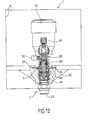
- Figure 12 corresponds to a section B-B in Figure 11.
- a non-return valve 80 is disposed between a first drain 81 before valve and a second purge 82 after valve according to the direction of normal circulation of the fluid towards the subscriber.
- Finger 83 of fixed control acts on the shutter member 6 downstream and its ball 61.
- the downstream obturation member 6 comprises means elastic closure to guarantee watertightness no downstream pressure when the metering assembly 10 is took of.
- the finger 83 is omitted, the pressure of the upstream fluid being sufficient to open the shutter member.
- purge 82 can be eliminated.
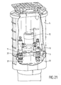
- a shell 5 is shown and the whole forms a look or terminal.
- the background of the gaze or terminal corresponds to base 2.
- the shape of the shell is suitable for envisaged applications.
- the base forms a tank bottom.
- Figure 21 represents a look of which part of the shell has been cut in order to visualize the system of the invention applied to a counting set. Part of the base has also been set to view the titler and the two nipples.
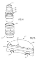
- Figure 14 concerns the nipple and the cartridge 60 of the shutter member is disassembled and separated.
- a means of grip 63 a hexagon in this example, allows the screwing of the cartridge to form the nipple.
- An external thread 28 allows mounting a tube for maintenance of the cartridge while the fluid is under pressure in the circuit.
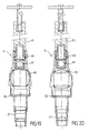
- the support 20 shown in Figure 15 is in two parts complementary coming into contact with each other in a plane passing through upstream 26 and downstream 27 orifices in which are arranged the corresponding nipples.
- the nipples are held fixed vertically by a system of imprint and counterprint which nevertheless authorizes a horizontal translation in the case of the downstream passage orifice 27 which is oblong.
- At least one of the two connecting nipples has freedom of translation thanks to an oblong housing or passage opening in the support 20, which gives the possibility to receive variable length meters, without socket telescopic. Thanks to entry chamfers on the ends upstream and downstream of the counter which facilitate their introduction on the nipples, the distance between the 2 nipples is adjusted when the establishment. This arrangement allows all of counting to receive meters of different lengths without require telescopic socket. Indeed the standard of achievement counters provides a certain tolerance for making lengths and, in the same range of counter, supplies, especially with different manufacturers, lead to deviations important in length.
- the support 20 therefore consists of two half-parts, of which the assembly traps the obturator or nipple assemblies upstream and downstream.
- the fingerprints intended to receive them may have grooves to hold the nipples according to the vertical axis while allowing the possibility of translation necessary for indexing on meter lengths. The assembly is thus facilitated and does not require any part additional for holding in position.
- the nipples are also immobilized in rotation by complementary flat surfaces of the nipples (see Figures 5 to 10 for example) and upstream passage openings (not shown) 26 and downstream 27.
- the two complementary parts of the support 20 are held together by all classic means including two half-shells united with two parts of the support and thus forming the outer shell 5.
- an operating key 4 is arranged on the means to operate the tap before counter 7 in a manhole.
- the same operating key 4 is used for locking and unlocking the system and opening and closing the valve before counter.
- the operating key 4 therefore allows the handling of the tap before meter and moving the drawer 3 or slide of the mobile guillotine fixing means.
- a tool is used which can be the same as the operating key of the front counter valve.
- This tool consists of a square tube whose interior dimensions are those of the operating square 75 of the front counter tap 7.
- This key is inserted into an orifice engagement circular 25 produced in the support 20 of the base 2 allowing axial and vertical blind holding during rotation of the key.
- An operating finger 40 disposed transversely in the tube carries out the training of the drawer 3 of the guillotine by through a notch 33.
- the rotation of the key causes the guillotine drawer to move, making the blocking - unblocking of the counting assembly.
- Tool 9 is formed externally from a tube 90 comprising a shutter sphere 92 whose rotation is controlled from the outside by a handle 93. The sphere is pierced in its center.
- an extractability system 91 is arranged in the tube 90 and engages on the engagement means 63 of the organ obturation which can then be unscrewed from the nipple thanks to a tee end.
- Sealing means, O-ring on the system 91 allow to work with the fluid under pressure.
- Tool 9 for replacing the shutter cartridge 60 guarantees total and very simple maintenance of all. It allows the exchange of the shutter member, its seat, seals and contact spring under pressure, without interruption of the fluid. It therefore consists of a tube 90, with a thread at its end and a groove for O-ring and at the other end of an airlock, consisting of a tap with quarter-turn ball, for example.
- a system extractor 91 of the shaft type with an adjusted outside diameter on the inside diameter of the tube and fitted with a seal, with seal toric for example, has a temporary hanging device spring ball type which can receive the shutter member at replace, fitted with its internal components, seat, ball, spring, seal, and a rotary drive system, type 6 sides for example, for driving the gripping means 63 corresponding nipple to replace.
- the maintenance operation initially consists of: disassemble the counting assembly and then disassemble the drawer 3 of the guillotine by translation so that the lugs 34 come in relationship with the notches 24 then screw the tube 90 onto the nipple at the bottom of the tank and open the airlock by rotating the shutter sphere.
- Disassembly of the metering assembly may require opening a lock or padlock or destroying a loop witness, a rivet or an umbrella head nail. These latter means are kept both in the support and in the drawer and lock the system in the locked position. It is therefore necessary to disassemble them to unlock the system and they are therefore witnesses or safeties to ensure that the absence of untimely action or attempted fraud in the case of a counting assembly.
- Using a rivet or nail umbrella head only requires an opening through base 20 at level of a lug 34 of the drawer 3.
- the umbrella head nail can be introduced without difficulty, the head being folded, but it cannot be removed without being destroyed because the head is deployed after crossing base and drawer.
- the shutter member 6 has been unscrewed by rotation of the extractor system shaft 91, until the thread on the nipple socket and it is reassembled in the tube at beyond the sphere 92.
- the pressure of the water, in particular upstream, helps to raise the shaft + nipple assembly and its internal components.
- the sphere 92 is tilted in order to close the airlock and it is then possible to extract the closure member 6 from the tube 90. As soon as the airlock is crossed and closing of it by rotation of the shutter sphere 92, the shutter member 6 perhaps replaced at the end of the tree, out of water then the assembly is reinserted or changed and reassembled or assembled, in stages inverses.
- any type of fluid can be supported with the system described.
- one or more circuits can benefit from the invention, for example a double hot and cold water counting with four nipples and four ends which can be arranged in line or in parallel.
- electrical harnesses can be associated with a fluid and electric mixed system.
- a fluid and electric mixed system can be connected between an input and an output via a removable module.
- the electrical connection cannot concern one or both ends and nipple.
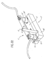
- Figure 22 shows an example of system application of attachment to electrical circuits.
- 21 'and 22' nipples receive electrical conductors not shown.
- the 11 'and 12' ends were arranged in interpenetration with the nipples 21 'and 22' so that the locking edges of the drawer 3 ' block them between themselves.
- the drawer is movable in translation and its maneuver is preferably carried out using a 4 'key.
- the circuits nipples are connected to the circuits extremities. When the removable part 1 'is separated from the 2 'base, isolation devices can be activated so that the ends and nipples circuits are not accessible directly.
Applications Claiming Priority (2)
| Application Number | Priority Date | Filing Date | Title |
|---|---|---|---|
| FR0106753A FR2825149B1 (fr) | 2001-05-22 | 2001-05-22 | Systeme de fixation d'un module amovible sur des circuits avec verrouillage par guillotine |
| FR0106753 | 2001-05-22 |
Publications (1)
| Publication Number | Publication Date |
|---|---|
| EP1265056A1 true EP1265056A1 (de) | 2002-12-11 |
Family
ID=8863561
Family Applications (1)
| Application Number | Title | Priority Date | Filing Date |
|---|---|---|---|
| EP02291265A Withdrawn EP1265056A1 (de) | 2001-05-22 | 2002-05-22 | Befestigungssystem für ein abnehmbares modul in einem Kreis mit Schiebeverriegelung |
Country Status (2)
| Country | Link |
|---|---|
| EP (1) | EP1265056A1 (de) |
| FR (1) | FR2825149B1 (de) |
Cited By (7)
| Publication number | Priority date | Publication date | Assignee | Title |
|---|---|---|---|---|
| FR2925537A1 (fr) * | 2007-12-19 | 2009-06-26 | Hydromeca Sa | Regard equipe d'au moins un compteur en ligne |
| ITBS20100004A1 (it) * | 2010-01-15 | 2011-07-16 | Tiemme Raccorderie S P A | Cassetta contatori per impianti domestici di distribuzione, ad esempio per impianti di distribuzione dell'acqua calda o fredda |
| FR2981374A1 (fr) * | 2011-10-17 | 2013-04-19 | Persohn Sa | Perfectionnement aux dispositifs de raccordement de compteur d'eau et ensemble hydraulique pour compteur d'eau le comprenant |
| CN104879567A (zh) * | 2015-04-30 | 2015-09-02 | 无锡市星翼仪表科技有限公司 | 新型管道固定装置 |
| AT518963A1 (de) * | 2016-07-28 | 2018-02-15 | Techem Energy Services Gmbh | Verbindungsvorrichtung für ein einrohranschlussstück |
| CN108444514A (zh) * | 2018-06-28 | 2018-08-24 | 广东电网有限责任公司 | 仪表挂设装置及仪表固定系统 |
| CN110470358A (zh) * | 2019-09-20 | 2019-11-19 | 山东力创科技股份有限公司 | 一种组合式多用户水表 |
Families Citing this family (3)
| Publication number | Priority date | Publication date | Assignee | Title |
|---|---|---|---|---|
| FR2865485B1 (fr) * | 2004-01-23 | 2006-03-17 | Manuf D App Electr De Cahors M | Dispositif et procede pour fixer un appareil, notamment un compteur d'eau, entre deux elements tubulaires de raccordement fixes, notamment disposes dans un regard enterre |
| FR2883371B1 (fr) * | 2005-03-16 | 2007-11-02 | Manuf D App Electr De Cahors M | Support et accessoires pour supporter et fixer une installation de comptage d'eau dans un regard enterre et installation de comptage fixee avec un tel support |
| CN109914534A (zh) * | 2019-03-08 | 2019-06-21 | 广东宜瑞环境科技有限公司 | 一种变频恒压节能供水设备 |
Citations (5)
| Publication number | Priority date | Publication date | Assignee | Title |
|---|---|---|---|---|
| US2241484A (en) * | 1939-05-31 | 1941-05-13 | Orlin N Sellers | Meter connection |
| US3929356A (en) * | 1974-11-13 | 1975-12-30 | Gen Motors Corp | Tube to block mounting assembly |
| GB2138910A (en) * | 1983-04-22 | 1984-10-31 | George Brookes | Gas supply conduit system |
| FR2798182A1 (fr) * | 1999-09-08 | 2001-03-09 | Sainte Lizaigne Sa | Dispositif pour reseau d'adduction d'eau, base et module le composant et son application aux ensembles de comptage |
| FR2800401A1 (fr) * | 1999-10-29 | 2001-05-04 | Sainte Lizaigne Sa | Dispositif a raccord amovible et a clapet commande pour reseau d'adduction d'eau et ensemble de comptage le mettant en oeuvre |
-
2001
- 2001-05-22 FR FR0106753A patent/FR2825149B1/fr not_active Expired - Lifetime
-
2002
- 2002-05-22 EP EP02291265A patent/EP1265056A1/de not_active Withdrawn
Patent Citations (5)
| Publication number | Priority date | Publication date | Assignee | Title |
|---|---|---|---|---|
| US2241484A (en) * | 1939-05-31 | 1941-05-13 | Orlin N Sellers | Meter connection |
| US3929356A (en) * | 1974-11-13 | 1975-12-30 | Gen Motors Corp | Tube to block mounting assembly |
| GB2138910A (en) * | 1983-04-22 | 1984-10-31 | George Brookes | Gas supply conduit system |
| FR2798182A1 (fr) * | 1999-09-08 | 2001-03-09 | Sainte Lizaigne Sa | Dispositif pour reseau d'adduction d'eau, base et module le composant et son application aux ensembles de comptage |
| FR2800401A1 (fr) * | 1999-10-29 | 2001-05-04 | Sainte Lizaigne Sa | Dispositif a raccord amovible et a clapet commande pour reseau d'adduction d'eau et ensemble de comptage le mettant en oeuvre |
Cited By (8)
| Publication number | Priority date | Publication date | Assignee | Title |
|---|---|---|---|---|
| FR2925537A1 (fr) * | 2007-12-19 | 2009-06-26 | Hydromeca Sa | Regard equipe d'au moins un compteur en ligne |
| ITBS20100004A1 (it) * | 2010-01-15 | 2011-07-16 | Tiemme Raccorderie S P A | Cassetta contatori per impianti domestici di distribuzione, ad esempio per impianti di distribuzione dell'acqua calda o fredda |
| FR2981374A1 (fr) * | 2011-10-17 | 2013-04-19 | Persohn Sa | Perfectionnement aux dispositifs de raccordement de compteur d'eau et ensemble hydraulique pour compteur d'eau le comprenant |
| CN104879567A (zh) * | 2015-04-30 | 2015-09-02 | 无锡市星翼仪表科技有限公司 | 新型管道固定装置 |
| AT518963A1 (de) * | 2016-07-28 | 2018-02-15 | Techem Energy Services Gmbh | Verbindungsvorrichtung für ein einrohranschlussstück |
| AT518963B1 (de) * | 2016-07-28 | 2018-11-15 | Techem Energy Services Gmbh | Verbindungsvorrichtung für ein einrohranschlussstück |
| CN108444514A (zh) * | 2018-06-28 | 2018-08-24 | 广东电网有限责任公司 | 仪表挂设装置及仪表固定系统 |
| CN110470358A (zh) * | 2019-09-20 | 2019-11-19 | 山东力创科技股份有限公司 | 一种组合式多用户水表 |
Also Published As
| Publication number | Publication date |
|---|---|
| FR2825149B1 (fr) | 2003-09-05 |
| FR2825149A1 (fr) | 2002-11-29 |
Similar Documents
| Publication | Publication Date | Title |
|---|---|---|
| EP1265056A1 (de) | Befestigungssystem für ein abnehmbares modul in einem Kreis mit Schiebeverriegelung | |
| EP1219885A1 (de) | Steckdosenelement und Schnellkupplung und Vorrichtung die ein solches Element enthält | |
| EP0654852A1 (de) | Gemischter elektrofluidischer Verbinder | |
| CH671816A5 (de) | ||
| EP2306060B1 (de) | Fluidverteilungsanschluss, insbesondere für medizinisches Gas oder Vakuum | |
| FR2807813A1 (fr) | Boitier de vanne de melange de robinet muni de clapets de retenue et d'un filtre | |
| FR2819876A1 (fr) | Module de bloc changeur de teinte pour installation de peinture | |
| EP3056782B1 (de) | Anschlussorgan auf einer leitung, das ein bewegliches verriegelungsendstück zum verbinden der leitung mit einer zweiten leitung umfasst | |
| FR2800401A1 (fr) | Dispositif a raccord amovible et a clapet commande pour reseau d'adduction d'eau et ensemble de comptage le mettant en oeuvre | |
| EP2247799A2 (de) | Vorrichtung zur montage und verbindung von sanitäreinrichtungsrohren an einer wand sowie entsprechendes verfahren | |
| FR3043162A1 (fr) | Dispositif de raccordement d’un element de robinetterie et d’un conduit d’alimentation au travers d’une cloison | |
| EP2204600B1 (de) | Gasanschluss für die Verbindung zwischen einem Festnetz zur Versorgung von gasförmigem Fluid und einem Gerät, das mit dem gasförmigen Fluid versorgt wird | |
| EP0277898A1 (de) | Gehäuse für Fluidleitungen im Mauerwerk | |
| FR3016950A1 (fr) | Raccord pour circuit de transport de fluide et circuit de transport de fluide comprenant un tel raccord | |
| WO2008071864A2 (fr) | Moyens de fixation d'un element de robinetterie sur une paroi | |
| EP2063029A1 (de) | Verteiler und eine solche Vorrichtung umfassendes Leitungssystem | |
| FR2552842A1 (fr) | Robinet d'arret a boule avec canal d'ecoulement a profil modifiable | |
| FR2798182A1 (fr) | Dispositif pour reseau d'adduction d'eau, base et module le composant et son application aux ensembles de comptage | |
| EP2161193A2 (de) | Bedarfgesteuertes Ventil für Taucher und Organ zur selektiven Flüssigkeitsverbindung | |
| EP2867417A1 (de) | Modulare konstruktion für elektronische armatur | |
| WO1995031664A1 (fr) | Ensemble vanne-clapet d'isolement et application notamment a un poste de comptage d'eau | |
| FR2892492A1 (fr) | Dispositif de securisation pour un organe d'un circuit, raccord de conduit et vanne comportant un tel dispositif. | |
| EP3436396B1 (de) | Prüf- oder fülladapter mit einem sicherheitskörper | |
| EP1262743A1 (de) | Einrichtung zum Anschluss für eine Wasserzähleranlage | |
| EP0719973A1 (de) | Verbindungsrohrelement, Vorrichtung und Rohrverbindungsanordnung, insbesondere für Gasleitungen |
Legal Events
| Date | Code | Title | Description |
|---|---|---|---|
| PUAI | Public reference made under article 153(3) epc to a published international application that has entered the european phase |
Free format text: ORIGINAL CODE: 0009012 |
|
| AK | Designated contracting states |
Kind code of ref document: A1 Designated state(s): AT BE CH CY DE DK ES FI FR GB GR IE IT LI LU MC NL PT SE TR |
|
| AX | Request for extension of the european patent |
Free format text: AL;LT;LV;MK;RO;SI |
|
| 17P | Request for examination filed |
Effective date: 20030611 |
|
| AKX | Designation fees paid |
Designated state(s): DE ES GB IT |
|
| 17Q | First examination report despatched |
Effective date: 20071024 |
|
| RAP1 | Party data changed (applicant data changed or rights of an application transferred) |
Owner name: MANUFACTURE D'APPAREILLAGE ELECTRIQUE DE CAHORS - Owner name: SAINTE-LIZAIGNE S.A. |
|
| GRAP | Despatch of communication of intention to grant a patent |
Free format text: ORIGINAL CODE: EPIDOSNIGR1 |
|
| RIC1 | Information provided on ipc code assigned before grant |
Ipc: G01F 15/18 20060101AFI20170131BHEP Ipc: E03B 7/09 20060101ALI20170131BHEP Ipc: E03B 7/07 20060101ALI20170131BHEP |
|
| INTG | Intention to grant announced |
Effective date: 20170228 |
|
| GRAS | Grant fee paid |
Free format text: ORIGINAL CODE: EPIDOSNIGR3 |
|
| STAA | Information on the status of an ep patent application or granted ep patent |
Free format text: STATUS: THE APPLICATION IS DEEMED TO BE WITHDRAWN |
|
| 18D | Application deemed to be withdrawn |
Effective date: 20170711 |
|
| RIC1 | Information provided on ipc code assigned before grant |
Ipc: G01F 15/18 20060101AFI20170131BHEP Ipc: E03B 7/09 20060101ALI20170131BHEP Ipc: E03B 7/07 20060101ALI20170131BHEP |