EP2204600B1 - Gasanschluss für die Verbindung zwischen einem Festnetz zur Versorgung von gasförmigem Fluid und einem Gerät, das mit dem gasförmigen Fluid versorgt wird - Google Patents
Gasanschluss für die Verbindung zwischen einem Festnetz zur Versorgung von gasförmigem Fluid und einem Gerät, das mit dem gasförmigen Fluid versorgt wird Download PDFInfo
- Publication number
- EP2204600B1 EP2204600B1 EP08291264A EP08291264A EP2204600B1 EP 2204600 B1 EP2204600 B1 EP 2204600B1 EP 08291264 A EP08291264 A EP 08291264A EP 08291264 A EP08291264 A EP 08291264A EP 2204600 B1 EP2204600 B1 EP 2204600B1
- Authority
- EP
- European Patent Office
- Prior art keywords
- valve
- outlet fitting
- spherical ball
- valve body
- connecting end
- Prior art date
- Legal status (The legal status is an assumption and is not a legal conclusion. Google has not performed a legal analysis and makes no representation as to the accuracy of the status listed.)
- Active
Links
- 239000012530 fluid Substances 0.000 title claims abstract description 33
- 230000001681 protective effect Effects 0.000 claims description 87
- 230000000007 visual effect Effects 0.000 claims description 18
- 230000006835 compression Effects 0.000 claims description 17
- 238000007906 compression Methods 0.000 claims description 17
- 230000000903 blocking effect Effects 0.000 claims description 9
- 238000011144 upstream manufacturing Methods 0.000 claims description 9
- 230000000717 retained effect Effects 0.000 claims description 8
- 239000007789 gas Substances 0.000 description 97
- 238000007789 sealing Methods 0.000 description 11
- 239000008188 pellet Substances 0.000 description 9
- 230000035515 penetration Effects 0.000 description 5
- 239000007769 metal material Substances 0.000 description 3
- 230000000284 resting effect Effects 0.000 description 3
- XKRFYHLGVUSROY-UHFFFAOYSA-N Argon Chemical compound [Ar] XKRFYHLGVUSROY-UHFFFAOYSA-N 0.000 description 2
- IJGRMHOSHXDMSA-UHFFFAOYSA-N Atomic nitrogen Chemical compound N#N IJGRMHOSHXDMSA-UHFFFAOYSA-N 0.000 description 2
- 108010044349 Maxitrol Proteins 0.000 description 2
- 230000009471 action Effects 0.000 description 2
- 239000000470 constituent Substances 0.000 description 2
- UREBDLICKHMUKA-CXSFZGCWSA-N dexamethasone Chemical compound C1CC2=CC(=O)C=C[C@]2(C)[C@]2(F)[C@@H]1[C@@H]1C[C@@H](C)[C@@](C(=O)CO)(O)[C@@]1(C)C[C@@H]2O UREBDLICKHMUKA-CXSFZGCWSA-N 0.000 description 2
- 238000004519 manufacturing process Methods 0.000 description 2
- 229940029062 maxitrol Drugs 0.000 description 2
- 229910052786 argon Inorganic materials 0.000 description 1
- QVGXLLKOCUKJST-UHFFFAOYSA-N atomic oxygen Chemical compound [O] QVGXLLKOCUKJST-UHFFFAOYSA-N 0.000 description 1
- 235000021168 barbecue Nutrition 0.000 description 1
- 239000011324 bead Substances 0.000 description 1
- 230000008878 coupling Effects 0.000 description 1
- 238000010168 coupling process Methods 0.000 description 1
- 238000005859 coupling reaction Methods 0.000 description 1
- 210000005069 ears Anatomy 0.000 description 1
- 229920001971 elastomer Polymers 0.000 description 1
- 239000000806 elastomer Substances 0.000 description 1
- 239000011261 inert gas Substances 0.000 description 1
- 230000007257 malfunction Effects 0.000 description 1
- 239000000463 material Substances 0.000 description 1
- 230000007246 mechanism Effects 0.000 description 1
- 230000004048 modification Effects 0.000 description 1
- 238000012986 modification Methods 0.000 description 1
- 229910052757 nitrogen Inorganic materials 0.000 description 1
- 239000001301 oxygen Substances 0.000 description 1
- 229910052760 oxygen Inorganic materials 0.000 description 1
Images


Classifications
-
- F—MECHANICAL ENGINEERING; LIGHTING; HEATING; WEAPONS; BLASTING
- F16—ENGINEERING ELEMENTS AND UNITS; GENERAL MEASURES FOR PRODUCING AND MAINTAINING EFFECTIVE FUNCTIONING OF MACHINES OR INSTALLATIONS; THERMAL INSULATION IN GENERAL
- F16L—PIPES; JOINTS OR FITTINGS FOR PIPES; SUPPORTS FOR PIPES, CABLES OR PROTECTIVE TUBING; MEANS FOR THERMAL INSULATION IN GENERAL
- F16L37/00—Couplings of the quick-acting type
- F16L37/28—Couplings of the quick-acting type with fluid cut-off means
- F16L37/38—Couplings of the quick-acting type with fluid cut-off means with fluid cut-off means in only one of the two pipe-end fittings
- F16L37/47—Couplings of the quick-acting type with fluid cut-off means with fluid cut-off means in only one of the two pipe-end fittings with a tap or cock
-
- F—MECHANICAL ENGINEERING; LIGHTING; HEATING; WEAPONS; BLASTING
- F16—ENGINEERING ELEMENTS AND UNITS; GENERAL MEASURES FOR PRODUCING AND MAINTAINING EFFECTIVE FUNCTIONING OF MACHINES OR INSTALLATIONS; THERMAL INSULATION IN GENERAL
- F16L—PIPES; JOINTS OR FITTINGS FOR PIPES; SUPPORTS FOR PIPES, CABLES OR PROTECTIVE TUBING; MEANS FOR THERMAL INSULATION IN GENERAL
- F16L37/00—Couplings of the quick-acting type
- F16L37/60—Couplings of the quick-acting type with plug and fixed wall housing
Definitions
- the invention relates to a gas intake fed on the one hand fixedly by a fixed conduit for supplying a gaseous fluid, and allowing the connection and disconnection of a male-type connection nozzle which supplies gaseous fluid through a pipe. flexible a gas-operated appliance.
- the known gas intakes are designed to allow a quick and easy connection and disconnection between a fixed supply network of gaseous fluid, in particular of combustible gas, installed inside a building and a functioning apparatus.
- gas such as a gas stove, a heater, a dryer, or a barbecue, for example.
- the known gas intakes generally comprise a housing which has a gas inlet connection provided for the making of a fixed connection of the gas intake with a fixed gas line, a female-type outlet connection intended to connect a gas connection.
- male-type tip connected by flexible hose to the gas-operated apparatus, and a valve provided to block the fluid in the disconnected position or to ensure the flow of gas when the nozzle is connected to the gas outlet fitting, as described for example in DE-A-35 199 33 , WO-A-02/48597 and DE-A-10 2006 010 565 .
- DE-A-35 199 33 discloses a rotary valve gas intake in which the rotary member of the valve rotates in the axis of the valve outlet connection.
- This gas intake has a tubular gas passage body capable of rotating in a housing and intended to receive a gas connection nozzle, and a gas inlet channel which is oriented perpendicularly to the gas passage body.
- the locking member is composed of a ball provided with a perpendicular ball channel, which ball is rotatable about the longitudinal axis of the gas passage body.
- the inlet end of the gas passage body makes protrusion in the outlet end of the ball channel and is coupled integrally in rotation with the ball.
- the ball is supported by its diametrically opposite sides in the longitudinal direction of the inlet channel against two elastic sealing rings of the housing, a sealing ring of which is arranged on a fitting embedded in the inlet channel, with which the sealing ring can be pressed against the ball.
- the branch bore does not provide any protection against manipulation, in particular for the sealing ring that is in this bore.
- this gas intake does not include a protection device against the penetration of a foreign body inside the connection bore and against the action of light on the sealing ring.
- this embodiment is not suitable for flush mounting.
- WO-A-02/48597 and DE-A-10 2006 010 565 disclose, for example, a gas intake having a housing having a gas inlet fitting adapted to be permanently connected to a fixed gas line, a female type outlet fitting adapted to connect a suitable hose connector connected by a hose to a gas-operated apparatus, and a flapper valve that locks the fluid in the disconnected position or provides gas flow when the nozzle is sealingly connected to the outlet fitting.
- the gas intake described in WO-A-02/48597 has a case face provided with a vertically elongated opening, and a sliding protective cover on the downstream side of the case face which closes the opening formed in the case when the tip is not connected.
- the guard has a tip placement port fitted to a hood lock and located in a position offset from the gas outlet fitting port.
- the end cap To unlock the guard locking system, the end cap must be inserted into the end cap placement hole of the guard, and then, so that the end cap can be connected to the outlet fitting, the end cap must be slid by translation, forcing the protective cap into a position where the orifice of the outlet fitting is accessible to connect the tip.
- the protective cover When disconnecting the nozzle, the protective cover automatically returns to its original position where it closes the orifice of the gas outlet fitting.
- the gas outlet fitting is housed in a housing, and the housing has an external protective cover protecting the gas outlet, this protective hood being provided with an external recess and an internal locking device which can be unlocked by inserting the tip into the recess.
- the protective cover When disconnecting the nozzle, the protective cover automatically returns to its original position where it closes the orifice of the gas outlet fitting.
- the protective cover is unlocked by means of the nozzle.
- a major disadvantage common to these sockets is that a pull applied to the tip may lead to accidental disconnection of the tip.
- the tip can be disconnected even if the valve is not closed.
- these gas intakes do not include a valve opening indicator.
- This safety fitting comprises a valve comprising a valve body having a pressurized fluid inlet connection and a spherical plug rotatably mounted within the valve body and having a pressurized fluid outlet connection of female type for connecting a male type nozzle, said ball valve being adapted to pivot between a position where the axis of the inlet fitting in the valve body is at a 90 ° angle to the coupling axis of the ball valve and where the valve is closed, and a position where the axis of the inlet fitting is in alignment with the axis of the outlet fitting and the valve is open.
- valve body is surrounded by an outer hemispherical protective sleeve having an opening and being pivotable about the valve body so as to protect the orifice of the outlet fitting when the nozzle is disconnected. either to allow the release of the outlet of the ball valve to connect the nozzle, or to block the rotation of the nozzle when it is connected to the outlet fitting and the valve is open.
- the sleeve When the valve is open, the sleeve returns to its initial position to lock the ball valve provided with the nozzle so as to prevent its rotation and thus prevent accidental disconnection of the tip.
- This safety connection has a disadvantage in that the release of the ball valve can be performed even if the tip is not connected.
- this pressurized fluid safety connection is designed to connect two flexible hoses, and is not at all suitable for use as a wall-mounted gas outlet for fixed connection to a fixed supply network. of gaseous fluid.
- the present invention proposes to provide a wall gas outlet intended to be fixedly connected to a fixed network for supplying gaseous fluid, which overcomes the disadvantages of known gas intakes.
- the present invention relates to a gas intake intended to be fixedly connected to a fixed gaseous fluid supply network, and allowing the connection and disconnection of a suitable male-type connection end which supplies gaseous fluid
- a gas-operated apparatus comprising a housing having a front provided with an elongated vertical opening and a protective cover designed to close the opening in the front of the housing, said housing housing a rotary valve comprising a valve body and a ball valve, wherein: said valve body is attached to the housing, and has on the upstream side an integrated gaseous fluid inlet connection for fixed connection to a fixed gaseous supply line, and has on the downstream side an integrated mounting housing for rotational mounting of the ball valve, the downstream side portion of the mounting housing With an opening, said ball valve has on the downstream side, facing the opening of the housing facade, a fluid outlet connection integrated gas nozzle for connecting a suitable male-type connecting piece, said ball valve being adapted to pivot on an axis of rotation between a position where the valve is closed and a position where the valve
- the rotary valve may comprise a device provided for sealing between the valve body and the ball valve.
- the outlet fitting may have on its outer surface on the downstream side at least one O-ring seal.
- the locking system which prevents the rotation of the ball valve is designed to be unlocked by axial thrust of the connecting piece on the outlet fitting.
- the locking system may include machined portions in the inner surface of the ball valve mounting housing of the valve body and upstream members on the outlet port of the ball valve.
- the protective cover is rotatably mounted relative to the front of the housing on an axis of rotation so that it can pivot about the axis of rotation of the plug spherical
- the front of the housing comprises a front portion having the elongate vertical opening and a slot forming a passage for the protective cover, said protective cover being designed to allow its revolution through the slot of the casing front without touching the end of the ball outlet fitting.
- the closure means of the protective cover preferably comprises a torsion spring mounted on the axis of rotation of the protective cover.
- the facade portion is preferably a portion of the front wall having a shape of revolution about the axis of rotation of the protective cover.
- the projecting façade portion comprises a first visual indicator and a second visual indicator different from the first visual indicator
- the protective cover comprises at least one orifice closed by a transparent lens, this transparent lens making it possible to see the first visual indicator. or the second visual indicator on the front part behind the protective cover in a state of closure of the protective cover corresponding to a closed state of the valve or a state of opening of the valve.
- the first visual indicator is preferably a green pellet
- said second visual indicator is preferably a red pellet
- said transparent lens for seeing said red pellet when the valve is closed and said green pellet when the valve is open.
- said valve body has in the inner surface of the ball housing, symmetrically from the downstream side of each side of the opening, a countersink, a first groove of bent guide and a second bent guide groove slightly further away from the axis of rotation of the ball valve than the first guide groove, said bead and said first and second grooves being machined portions in the inner surface of the bushing mounting housing spherical valve body and part of the locking system, said outlet fitting has on its upstream portion a groove for supporting a compression spring, and comprises the downstream side of the compression spring a locking ring slidable on the outlet fitting, these elements forming part of the locking system.
- the locking ring on the outlet fitting of the ball valve is locked in the countersink of the valve body when the valve is closed, thus blocking the rotation of the ball valve, said locking ring being released from the countersink by a thrust axial connection of the connection piece after connecting it to the outlet fitting to unlock the ball valve on the valve body and allow rotation of the ball valve.
- an outer shoulder of the connecting piece is in abutment against a locking surface formed at the downstream end of the second guide groove by the offset between the two guide grooves when the valve is open, thus blocking the rotation of the ball valve, said shoulder of the connection piece being able to be released from said blocking surface by axial thrust of the connection piece on the outlet fitting to unlock the connection piece on the valve body and to allow the rotation of the spherical ball.
- an outer shoulder of the connecting piece is retained in one of the first and second guide grooves during the operation of opening and closing the valve by rotation after unlocking the ball valve on the valve body. or unlocking the connection piece on the valve body.
- the adapted connection piece comprises a branch end having an inside diameter substantially equal to the outside diameter of the outlet fitting so that the connection piece can slide on the outer surface of the outlet fitting, said end connecting piece further comprising a flange having a shoulder, the inner surface of the adapted connecting piece further comprising a shoulder forming a stop for the downstream end of the outlet fitting when the end piece is slid all the way to the end of the stroke on the outer surface of the outlet fitting, the outer surface of the connecting piece further comprising a shoulder set back from the downstream side with respect to the inner shoulder so that this outer shoulder does not abut against the protective cap before the connection piece reaches its end-of-travel position in abutment against the outlet fitting.
- the gas intake of the present invention is a gas intake intended to be fixedly connected to a fixed line for supplying gaseous fluid, and it allows the secure connection and disconnection of a suitable male-type connection piece. which supplies gaseous fluid through a flexible hose to a gas-operated apparatus.
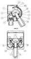
- FIGS. 1 to 13 show a preferred embodiment of a projecting wall gas intake of the present invention in its different operating situations or specific elements thereof and the Figures 14a-14d show the principle of operation of this gas intake, it being understood that the reference numbers indicated in these Figures are identical when identical parts are designated.
- Figures 1 and 2 show this gas intake in a position where the connection piece is not connected, the ball valve is locked on the valve body, the valve is closed and the protective cover closes the opening in the front of the housing
- Figures 5, 6 and 7 show this gas intake before unlocking the ball valve, in a position where the connection piece is connected to the outlet fitting, the seal is established between the connection piece and the ball valve, the valve is closed and the protective cover is open
- Figures 8 and 9 show this gas intake in a position where the connection piece is connected to the outlet fitting, the connection piece is retained on the valve body so as to prevent it from being disconnected, the ball is unlocked, the valve is still closed, the protective cover is resting on the connection end
- the Figures 10 and 11 show this gas intake in a position where the connection piece is connected to the outlet fitting, the connection piece is locked on the valve body so as to block the rotation of the ball valve, the valve is open, and the protective cover is supported on the connection piece.
- the wall gas intake 1 comprises a housing 2 having a front 3 provided with an elongated vertical opening 4 and a protective cover 5 rotatably mounted and designed to close the door. opening 4 in the front 3 of the housing 2 to prevent the penetration of foreign bodies into the housing.
- the housing 2 houses a rotary valve comprising a valve body 6, a spherical plug 7, and a shape gasket 8 sealing between the valve body 6 and the spherical plug 7.
- valve body 6 comprises an integrated fluid inlet fitting 9 , two integrated attachment lugs 10 having fixing holes 11 for attaching the valve body to the housing 2, and an integrated mounting housing 12 comprising two bearings 13 for the rotational mounting of the ball valve 7 and the fixing housing 14 for fixing the valve body 6 to the front 3.
- the fluid inlet connection 9 is located on the upstream side of the valve body 6 and the mounting housing 12 is located on the downstream side of the valve body 6, the downstream side portion of the mounting housing 12 having an opening 15.
- the fluid inlet fitting 9 may be connected to any fixed gaseous fluid supply line by means of a suitable adapter 16 .
- the fixed gaseous fluid supply line may be a combustible gas supply network pipe installed in a building, but may also be be a fixed supply line of any other gaseous fluid, for example a fixed supply line of oxygen in a hospital, a fixed supply line of inert gas such as nitrogen or argon in a laboratory or a production workshop, or others.
- gas intake of the present invention is particularly well suited for gas pressures up to 50 hectopascals (50 millibars). However, the gas intake of the present invention can also be used for higher gas pressures.
- the ball valve 7 is rotatably mounted in the mounting housing 12 of the valve body 6 at the bearings 13 so as to be pivotable between the position where the valve is closed as shown in FIGS. Figures 1 and 2 and the position where the valve is open as shown on the Figures 10 and 11 .
- the spherical plug 7 has on the downstream side an integrated outlet connector 17 facing the opening 15 of the mounting housing 12 and therefore facing the opening 4 in the front 3 of the housing.
- the outlet connector 17, of the female type is intended to connect a connection piece 18 of the appropriate male type as represented on the Figure 4 which will be described later.
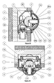
- the case facade 3 is an integrated case face including, as shown in more detail on Figures 12 and 13 , a first facade portion 3a of essentially flat shape slightly convex dictated by the aesthetic and a second front portion 3b protruding having a shape of revolution about the axis of rotation of the protective cover 5 having fixing holes 3c , and further comprising a slot 3d located at the junction of the first and second facade portions 3a and 3b in the upper part of the facade, this slot 3d forming a passage for the protective cover 5, the elongated vertical opening 4 allowing the connection of the connection piece 18 and the rotation of the ball valve 7 provided with the connection piece 18 to open the valve.
- the upper part of the second facade portion 3b has a first green patch 19 located near the slot 3d and a second patch 20 of red color located near from the upper end of the elongated opening 4.
- valve body 6 is fixed to the rear part of the casing 2 by fastening means passing through the fixing holes 11 and is fixed to the casing facade 3 by fastening means passing through the fixing holes 3c in the second part 3b and screwed into the fixing housing 14 of the valve body 6.
- valve body 6 is fastened to both the casing 2 and the casing facade 3.
- the fixing of the casing valve body 6 to the housing 2 is necessary, and this by any means of attachment.
- the rear face of the housing 2 is fixed to the outside of a wall, and therefore the gas intake is projecting outside the wall.
- the valve body 6 further comprises, in the inner surface of the mounting housing 12, symmetrically from the downstream side of each side of the opening 15, a countersink 21, a first curved guide groove 22 and a second groove 23 slightly curved further from the axis of rotation of the ball valve 7 than the first guide groove 22, these different machined parts forming part of the locking system of the valve.
- the outlet fitting 17 has on its outer surface on the downstream side two O-ring seals 24.
- outlet connection 17 has on its upstream part a groove 25 serving to support a compression spring 26, and comprises on the downstream side of the compression spring a locking ring 27 slidable on the outlet fitting 17, these different elements forming part of the locking system of the valve.
- the protective cover 5 is rotatably mounted with respect to the facade 3 so that it can pivot about the axis of rotation of the ball valve and is designed to allow its revolution by passing through the slot 3d of the casing facade without touching the end of the outlet fitting 17 of the ball valve 7.
- a torsion spring 28 is mounted on the rotation axis 29 of the protective cover.
- the torsion spring 28 constitutes a means of closing the protective cover and allows an automatic return thereof to its initial position in which it completely closes the opening 4 in the front of the housing 3, as shown more particularly on the Figures 1, 2 and 14a .
- the protective cover comprises a first orifice closed by a transparent lens 30a and a second orifice closed by a transparent lens 30b, these transparent lenses making it possible to see the front portion 3b bearing the green 19 and red 20 pellets behind the protective cover 5.
- valve body 6 and the ball valve 7 may be made of any suitable metallic material for use in a gas intake.
- the locking ring 27 may be made of any suitable metallic material for use as described above.
- Compression spring 26 and torsion spring 28 may be made of any suitable metallic material for use as described above.
- the seals can be made of any elastomer suitable for use in a wall gas outlet.
- the housing 2, the facade 3 and the protective cover 5 may be made of any plastic material suitable for use in a wall-mounted gas outlet.
- connection piece 18 adapted for connection to the outlet fitting 17 of the gas intake of the present invention has a branch end 18a having an inside diameter substantially equal to the outside diameter of the outlet fitting 17 so that the connection piece 18 can slide on the outer surface of the outlet connector 17.
- This connecting end 18a also comprises a flange 18b having a shoulder 18c whose size and shape are adapted for engagement and sliding in the guide grooves 22, 23.
- the inner surface of the connecting piece 18 has a circumferential shoulder 18d at a suitable distance so that this shoulder 18d forms a stop for the downstream end of the outlet fitting 17 when the connection piece 18 is slid to the end. end of stroke on the outer surface of the outlet fitting 17.
- the outer surface of the connecting piece 18 has a shoulder 18e set back from the downstream side relative to the inner shoulder 18d so that this outer shoulder 18e does not abut against the front protective cover 5 that the connection piece 18 has reached its end position in abutment against the outlet fitting 17.
- connection end piece having a profile meeting the above requirements is suitable, but preferably a suitable connection end fitting to the VP 635-1 or VP 635-2 standard will be used.
- the gas intake as shown on the Figures 1 and 2 is in a position of non-use, namely a complete closed position where the connecting piece 18 is not connected, the valve is closed and the protective cover 5 closes the opening 4 in the front 3 of the housing .
- the compression spring 26 on the outlet fitting 17 of the ball valve 7 is in its initial position, and the locking ring 27 downstream of the spring of compression 26 on the outlet fitting 17 is housed in the countersink 21 of the valve body 6, thereby locking the ball valve 7 on the valve body 6.
- the torsion spring 28 mounted on the axis of rotation 29 of the protective cover 5 is in its initial position ensuring the complete closure of the protective cover, thus preventing the penetration of foreign bodies into the housing 2.
- the upper transparent lens 30a closing the first hole in the protective cover 5 makes it possible to display the second patch 20 of red color located on the second front portion 3b, this red patch 20 serving as a closure indicator of the valve.
- the protective cover 5 is opened manually by rotating it about its axis of rotation as shown by the arrow on the Figure 14a then, while keeping the protective cover 5 open, the connection piece 18 is connected to the outlet connector 17 of the ball valve 7, as shown in FIG. Figure 14b to find themselves in the position represented on the Figures 5, 6 and 7 .
- FIGS 5, 6 and 7 represent the gas intake before the release of the ball valve 7, in a position where the connection piece 18 is connected to the outlet fitting 17, the seal is established between the connection piece 18 and the ball valve 7, the valve is closed and the protective cover 5 is retained by the connection piece 18.
- the manual opening of the protective cover 5 by pivoting about its axis of rotation loads the torsion spring 28 mounted on the axis of rotation 29 of the protective cover 5 and causes the passage of the protective cover 5 through the slot 3d of the front 3 to enter the housing 2 to the end of stroke where its rear portion abuts against an inner surface of the housing 2 or against the valve body 6 as shown more particularly on the Figure 5 .
- connection of the connection piece 18 is effected by sliding the inner surface of the connection piece 18 on the outer surface of the outlet fitting 17.
- connection piece 18 bears against the locking ring 27 and the connection piece 18 has exceeded the area of the outlet fitting 17 comprising the sealing O-rings 24, the sealing between the connection end 18 and the ball valve 7 is already established.
- the protective cover 5 is then returned to its initial closing position by the torsion spring 28 until it encounters the connecting end 18 in its path .
- the protective cover 5 is retained by the connection piece 18 and the lower transparent lens 30b closing the second orifice in the protective cover 5 makes it possible to display the second patch 20 of red color located on the second part of the facade 3b. There is therefore an indication that the valve is still closed.
- connection piece 18 axially on the outlet fitting 17 until it reaches the end of the stroke, namely that the shoulder 18d of the inner surface of the connection piece abuts against the downstream end of the outlet fitting 17, and that the compression spring 26 is in a fully compressed state, then rotate the connection piece 18 while now this one at the end of the race on the outlet fitting 17.
- connection piece 18 If the connection piece 18 is released before having engaged its pivoting, the compression spring 26 returns to its initial position and pushes the locking ring 27 back to its initial blocking position in the counterbore 21, thus automatically locking the plug spherical 7 on the valve body 6.
- the ball valve 7 can only be unlocked when the connection piece 18 is held end of stroke on the outlet fitting 17.
- connection piece 18 In this end-of-travel position of the connection piece 18, the locking ring 27 is disengaged from the counterbore 21, and the shoulder 18c of the collar 18b of the connection piece 18 is facing the downstream end. of the first curved guide groove 22 located in the inner surface of the mounting housing 12 of the valve body 6, ready to be engaged therein.
- connection piece 18 When starting the rotational movement of the connection piece 18, the shoulder 18c of the flange 18b of the connection piece 18 immediately engages in the first curved guide groove 22 of the valve body 6.
- connection piece 18 is retained in its end-of-travel position on the valve body 6 .
- connection piece 18 in its end position can no longer be disconnected from the outlet connector 17 .
- connection piece 18 During the rotational movement of the connection piece 18, the shoulder 18c of the flange of the connection piece 18 slides along the first curved guide groove 22 to end up in the situation shown in FIGS. Figures 8 and 9 .
- connection piece 18 By continuing the rotational movement of the connection piece 18, the shoulder 18c of the flange of the connection piece passes into the second guide groove 23 and then slides along it.
- the valve is in the open position after the shoulder 18c of the flange of the connection piece has passed into the second guide groove 23.
- connection piece 18 After the shoulder 18c of the flange of the connection piece has passed through the second guide groove 23, the connection piece 18 will go back under the action of the compression spring 26 on the locking ring 27 against which the end of the connection piece 18 is supported.
- connection piece 18 When the connection piece 18 is turned back , the shoulder 18c of the flange of the connection piece will slide in the second guide groove 23, but will abut against a locking surface formed at the end. downstream of the second guide groove 23 by the offset between the two guide grooves 22, 23, thus locking the connection piece 18 on the valve body 6 in a position where the valve is open, and preventing rotation of the plug spherical 6, to end up in the situation represented on the Figures 10, 11 and 14c .
- the protective cover 5 follows the movement of the connection piece to remain resting on it as shown in FIG. Figure 14c , and this thanks to the torsion spring 28 reminding the protective cover 5 in its initial closed position.
- the upper transparent lens 30a closing the first orifice in the protective cover 5 makes it possible to visualize the first green patch 19 located on the second facade portion 3b, this first patch 19 of green color serving as an opening indicator of valve.
- connection piece 18 To close the valve and disconnect the connection piece 18 from the outlet fitting 17 from the position where the valve is open shown on the Figures 10 and 11 , it is first necessary to push the connecting end 18 on the outlet connector 17 to the end of stroke to unlock the ball valve 7, then rotate the connection end 18, as shown by the two arrows on the Fig. 14d .
- connection piece 18 on the outlet fitting 17 causes the shoulder 18c of the flange of the connection piece of the locking surface formed at the downstream end of the second guide groove to disengage.
- the ball valve 7 can be unlocked only when the connection piece 18 is pushed axially end of stroke on the outlet fitting.
- connection piece 18 After unlocking the ball valve 7, the shoulder 18c of the connection piece 18 passes into the first guide groove 22, the valve closes, and we are in the position represented on the Figures 8 and 9 .
- connection piece 18 is retained in its end position on the valve body 6.
- the compression spring 26 returns to its initial position and pushes the locking ring 27 into its locking position in the countersink 21, thus automatically locking the ball valve 7 on the valve body 6 to prevent its rotation.
- the protective cover 5 remains resting on the connection piece while loading the torsion spring 28 mounted on the axis of rotation 29 of the protective cover 5.
- the lower transparent lens 30b closing the second orifice in the protective cover 5 makes it possible to visualize the second patch 20 of red color located on the second part of the facade 3b. There is therefore an indication that the valve is closed and that the tip can be removed.
- connection piece 18 From this position where the gas intake is secured, it is possible to disconnect the connection piece 18 by removing it axially from the outlet connection as represented by the arrow on the Figure 14e .
- the protective cover 5 automatically returns to its initial closed position, recalled by the torsion spring 28 as shown by the arrow on the Figure 14f to end up in the position of non-use represented on the Figures 1 and 2 .
- the torsion spring 28 In this non-use position, the torsion spring 28 is in its initial position ensuring the complete closure of the protective cover, and the upper transparent lens 30a closing the first orifice in the protective cover makes it possible to visualize the second color patch red on the front 3 of the housing, indicating that the valve is closed.
- a red pellet and a green pellet have been presented as visual indicators of the closed and open position of the valve, respectively.
- any other visual indicators can be used.
- the protective cover may comprise a single orifice closed by a transparent lens, this transparent lens making it possible to display the first visual indicator or the second visual indicator according to a state of closure of the protective cover corresponding to a state of closure of the valve. or an open state of the valve.
- FIGS. 15 and 16 show another preferred embodiment of a wall-mounted gas outlet of the present invention in its recessed version.
- Figures 15 and 16 show a concealed gas outlet in a non-use position where the connection piece is not not connected, the ball valve is locked on the valve body, the valve is closed and the protective cover closes the opening in the front of the housing.
- the wall gas outlet in its recessed version differs from the gas intake in its hull version as described above in that the housing 2 has a shape adapted to be embedded in the wall.
- this recessed wall gas outlet is identical to the operation of the wall gas outlet in its projecting version as described above.
- a projecting or recessed wall gas outlet with a secure rotary valve comprising a locking system preventing rotation of the ball valve by locking the ball valve on the valve body when the valve is closed. and by locking the connection piece to the valve body when the valve is open, the release of the ball valve on the valve body or the unlocking of the connection piece on the valve body can not take place that by an axial thrust of the connecting piece on the outlet of the ball valve before the rotation, thus providing safe protection vis-à-vis handling.
- this locking device also prevents accidental disconnection of the connection piece during the entire duration of the opening of the valve by retaining the connection piece on the valve body during this operation.
- this wall gas intake according to the invention comprises a closing means of the protective cover, thus preventing the penetration of foreign bodies into the housing.
Landscapes
- Engineering & Computer Science (AREA)
- General Engineering & Computer Science (AREA)
- Mechanical Engineering (AREA)
- Taps Or Cocks (AREA)
- Valve Housings (AREA)
- Sliding Valves (AREA)
Claims (15)
- Gasanschluss, der für die feste Verbindung mit einem Festnetz zur Versorgung von gasförmigem Fluid bestimmt ist und der das Anschließen und das Lösen eines passenden Einsteckverbindungsstücks gestattet, das ein Gerät, welches mit Gas funktioniert, durch einen Schlauch mit gasförmigem Fluid versorgt,
wobei der Gasanschluss ein Gehäuse (2) mit einer Vorderseite (3) aufweist, die mit einer länglichen, vertikalen Öffnung (4) und einer Schutzkappe (5), die zum Verschließen der Öffnung (4) in der Vorderseite (3) des Gehäuses bestimmt ist, versehen ist, wobei das Gehäuse (2) Sitz eines Drehventils ist, das einen Ventilkörper (6) und ein kugelförmiges Verschlussstück (7) aufweist, dadurch gekennzeichnet, dass:der Ventilkörper (6) an dem Gehäuse (2) befestigt ist und stromaufseitig einen Einlassstutzen von gasförmigem Fluid (9) aufweist, der für die feste Verbindung mit einer festen Leitung zur Versorgung von gasförmigem Fluid integriert ist, und stromabseitig einen Lagersitz (12) aufweist, der für die drehbare Lagerung des kugelförmigen Verschlussstücks (7) integriert ist, wobei der stromabseitige Abschnitt des Lagersitzes (12) eine Öffnung (15) aufweist,das kugelförmige Verschlussstück (7) stromabseitig, zu der Öffnung (4) der Vorderseite (3) des Gehäuses hin, einen integrierten Auslassstutzen von gasförmigem Fluid (17) aufweist, der zum Anschließen eines passenden Einsteckverbindungsstücks (18) vorgesehen ist, wobei das kugelförmige Verschlussstück (7) dafür ausgelegt ist, sich auf einer Drehachse zwischen einer Stellung, in der das Ventil geschlossen ist, und einer Stellung, in der das Ventil geöffnet ist, zu drehen,die längliche vertikale Öffnung (4) in der Vorderseite (3) dafür ausgelegt ist, das Anschließen des Verbindungsstücks (18) an den Auslassstutzen (17) und das Drehen des Verbindungsstücks (18), wenn dieses an dem Auslassstutzen (17) angeschlossen ist, zu gestatten,der Gasanschluss darüber hinaus umfasst:ein Verriegelungssystem, das die Drehung des kugelförmigen Verschlussstücks (7) durch Verriegeln des kugelförmigen Verschlussstücks (7) an dem Ventilkörper (6), wenn das Ventil geschlossen ist, und durch Verriegeln des Verbindungsstücks (18) an dem Ventilkörper (6) nach dessen Anschluss an den Auslassstutzen (17), wenn das Ventil geöffnet ist, verhindert, und das nach dem Entriegeln des kugelförmigen Verschlussstücks (7) an dem Ventilkörper (6) oder dem Entriegeln des Verbindungsstücks (18) an dem Ventilkörper (6) während der Vorgänge des Öffnens und des Schließens des Ventils durch Drehung das Verbindungsstück (18) an dem Ventilkörper (6) hält, undSchließmittel der Schutzkappe, die eine selbsttätige Rückwärtsbewegung der Schutzkappe (5) in eine Ausgangsstellung, in der sie die Öffnung (4) in der Vorderseite (3) des Gehäuses vollständig verschließt, gestatten. - Gasanschluss nach Anspruch 1, dadurch gekennzeichnet, dass das Drehventil darüber hinaus eine Vorrichtung (8) aufweist, die zum Sicherstellen der Dichtheit zwischen dem Ventilkörper (6) und dem kugelförmigen Verschlussstück (7) vorgesehen ist.
- Gasanschluss nach Anspruch 1 oder 2, dadurch gekennzeichnet, dass der Auslassstutzen (17) auf seiner stromabseitigen Außenfläche mindestens einen Runddichtring (24) aufweist.
- Gasanschluss nach einem der Ansprüche 1 bis 3, dadurch gekennzeichnet, dass das Verriegelungssystem, das die Drehung des kugelförmigen Verschlussstücks (7) verhindert, dafür ausgelegt ist, dass es durch einen Längsschub des Verbindungsstücks (18) an dem Auslassstutzen (17) entriegelt wird.
- Gasanschluss nach einem der Ansprüche 1 bis 4, dadurch gekennzeichnet, dass das Verriegelungssystem bearbeitete Abschnitte in der Innenfläche des Lagersitzes (12) für das kugelförmige Verschlussstück (7) des Ventilkörpers (6) und stromaufseitig angeordnete Elemente an dem Auslassstutzen (17) des kugelförmigen Verschlussstücks (7) aufweist.
- Wandgasanschluss nach einem der Ansprüche 1 bis 5, wobei die Schutzkappe (5) drehbar in Bezug auf die Vorderseite (3) des Gehäuses auf einer Drehachse (29) so gelagert ist, dass sie sich um die Drehachse des kugelförmigen Verschlussstücks (7) drehen kann, und wobei die Vorderseite (3) des Gehäuses einen Vorderseitenabschnitt (3b) mit der länglichen, vertikalen Öffnung (4) und einem Schlitz (3d), der einen Durchgang für die Schutzkappe (5) bildet, aufweist, wobei die Schutzkappe (5) so ausgelegt ist, dass ihre Drehung beim Passieren durch den Schlitz (3d) der Vorderseite des Gehäuses ohne Berühren des Endes des Auslassstutzens (17) des kugelförmigen Verschlussstücks (7) gestattet wird.
- Gasanschluss nach Anspruch 6, dadurch gekennzeichnet, dass die Schließmittel der Schutzkappe eine Torsionsfeder (28) umfassen, die auf der Drehachse (29) der Schutzkappe (5) gelagert ist.
- Gasanschluss nach Anspruch 6 oder 7, dadurch gekennzeichnet, dass der Vorderseitenabschnitt (3b) ein vorspringender Vorderseitenabschnitt ist, der eine Kreisform um die Drehachse (29) der Schutzkappe (5) aufweist.
- Gasanschluss nach einem der Ansprüche 6 bis 8, dadurch gekennzeichnet, dass der Vorderseitenabschnitt (3b) einen ersten Sichtanzeiger (19) und einen zweiten Sichtanzeiger (20), der anders als der erste Sichtanzeiger (19) ist, aufweist, wobei die Schutzkappe (5) mindestens ein durch eine transparente Linse (30a) verschlossenes Loch aufweist, wobei diese transparente Linse gestattet, den ersten Sichtanzeiger (19) oder den zweiten Sichtanzeiger (20) an dem Vorderseitenabschnitt (3b) hinter der Schutzkappe (5) gemäß einem Schließzustand der Schutzkappe (5), der einem Schließzustand des Ventils oder einem Öffnungszustand des Ventils entspricht, zu sehen.
- Gasanschluss nach Anspruch 9, dadurch gekennzeichnet, dass der erste Sichtanzeiger (19) ein grünes Plättchen ist, der zweite Sichtanzeiger (20) ein rotes Plättchen ist, wobei die transparente Linse (30a) gestattet, das rote Plättchen zu sehen, wenn das Ventil geschlossen ist, und das grüne Plättchen, wenn das Ventil geöffnet ist.
- Gasanschluss nach einem der Ansprüche 1 bis 10, dadurch gekennzeichnet, dass
der Ventilkörper (6) in der Innenfläche des Lagersitzes für das kugelförmige Verschlussstück (12), symmetrisch stromabseitig ausgehend von jeder Seite der Öffnung (15), eine Senkung (21), eine erste gekrümmte Führungsnut (22) und eine zweite gekrümmte Führungsnut (23), die etwas weiter von der Drehachse des kugelförmigen Verschlussstücks entfernt ist, als die erste Führungsnut (22), aufweist, wobei die Senkung (21) und die erste und die zweite Nut (22, 23) bearbeitete Abschnitte in der Innenfläche des Lagersitzes für das kugelförmige Verschlussstück (12) des Ventilkörpers (6) sind und Bestandteile des Verriegelungssystems sind,
der Auslassstutzen (17) auf seinem stromaufseitigen Abschnitt eine Rille (25) aufweist, die als Auflager für eine Druckfeder (26) dient, und stromabseitig von der Druckfeder einen Verriegelungsring (27) aufweist, der auf dem Auslassstutzen (17) gleiten kann, wobei diese Elemente Bestandteile des Verriegelungssystems sind. - Gasanschluss nach Anspruch 11, dadurch gekennzeichnet, dass der Verriegelungsring (27) an dem Auslassstutzen (17) des kugelförmigen Verschlussstücks (7) in der Senkung (21) des Ventilkörpers (6) blockiert ist, wenn das Ventil geschlossen ist, und so die Drehung des kugelförmigen Verschlussstücks (7) blockiert, wobei der Verriegelungsring (27) durch einen Längsschub des Verbindungsstücks (18) nach dessen Anschluss an den Auslassstutzen (17) aus der Senkung (21) ausgerückt werden kann, um das kugelförmige Verschlussstück (7) an dem Ventilkörper (6) zu entriegeln und die Drehung des kugelförmigen Verschlussstücks (7) zu gestatten.
- Gasanschluss nach Anspruch 11 oder 12, dadurch gekennzeichnet, dass ein äußerer Absatz (18c) des Verbindungsstücks (18) sich in Anschlag gegen eine Blockierfläche befindet, die am stromabseitigen Ende der zweiten Führungsnut (23) durch den Versatz zwischen den zwei Führungsnuten (22, 23) gebildet wird, wenn das Ventil geöffnet ist, und so die Drehung des kugelförmigen Verschlussstücks (7) blockiert, wobei der Absatz (18c) des Verbindungsstücks (18) durch einen Längsschub des Verbindungsstücks (18) an dem Auslassstutzen (17) aus der Blockierfläche ausgerückt werden kann, um das Verbindungsstück (18) an dem Ventilkörper (6) zu entriegeln und die Drehung des kugelförmigen Verschlussstücks (7) zu gestatten.
- Gasanschluss nach einem der Ansprüche 11 bis 13, dadurch gekennzeichnet, dass ein äußerer Absatz (18c) des Verbindungsstücks (18) während des Vorgangs des Öffnens und des Schließens des Ventils durch Drehung nach Entriegelung des kugelförmigen Verschlussstücks (7) an dem Ventilkörper (6) oder Entriegelung des Verbindungsstücks an dem Ventilkörper (6) in einer der ersten und der zweiten Führungsnut (22, 23) gehalten wird.
- Gasanschluss nach einem der Ansprüche 1 bis 14, dadurch gekennzeichnet, dass das passende Verbindungsstück (18) ein Anschlussende (18a) mit einem Innendurchmesser aufweist, der etwa gleich dem Außendurchmesser des Auslassstutzens (17) ist, so dass das Verbindungsstück (18) auf der Außenfläche des Auslassstutzens (17) gleiten kann, wobei das Anschlussende (18a) darüber hinaus einen Bund (18b) mit einem Absatz (18c) aufweist, wobei die Innenfläche des passenden Verbindungsstücks (18) darüber hinaus einen Absatz (18d) aufweist, der einen Anschlag für das stromabseitige Ende des Auslassstutzens (17) bildet, wenn das Verbindungsstück bis in die Endlage auf der Außenfläche des Auslassstutzens (17) gleiten gelassen wird, wobei die Außenfläche des Verbindungsstücks darüber hinaus einen Absatz (18e) aufweist, der stromabseitig im Verhältnis zum inneren Absatz (18d) zurückspringend angeordnet ist, so dass dieser äußere Absatz (18e) nicht gegen die Schutzkappe (5) anschlägt, bevor das Verbindungsstück (18) seine Endlage in Anschlag gegen den Auslassstutzen (17) erreicht hat.
Priority Applications (2)
| Application Number | Priority Date | Filing Date | Title |
|---|---|---|---|
| EP08291264A EP2204600B1 (de) | 2008-12-31 | 2008-12-31 | Gasanschluss für die Verbindung zwischen einem Festnetz zur Versorgung von gasförmigem Fluid und einem Gerät, das mit dem gasförmigen Fluid versorgt wird |
| AT08291264T ATE512332T1 (de) | 2008-12-31 | 2008-12-31 | Gasanschluss für die verbindung zwischen einem festnetz zur versorgung von gasförmigem fluid und einem gerät, das mit dem gasförmigen fluid versorgt wird |
Applications Claiming Priority (1)
| Application Number | Priority Date | Filing Date | Title |
|---|---|---|---|
| EP08291264A EP2204600B1 (de) | 2008-12-31 | 2008-12-31 | Gasanschluss für die Verbindung zwischen einem Festnetz zur Versorgung von gasförmigem Fluid und einem Gerät, das mit dem gasförmigen Fluid versorgt wird |
Publications (2)
| Publication Number | Publication Date |
|---|---|
| EP2204600A1 EP2204600A1 (de) | 2010-07-07 |
| EP2204600B1 true EP2204600B1 (de) | 2011-06-08 |
Family
ID=40651683
Family Applications (1)
| Application Number | Title | Priority Date | Filing Date |
|---|---|---|---|
| EP08291264A Active EP2204600B1 (de) | 2008-12-31 | 2008-12-31 | Gasanschluss für die Verbindung zwischen einem Festnetz zur Versorgung von gasförmigem Fluid und einem Gerät, das mit dem gasförmigen Fluid versorgt wird |
Country Status (2)
| Country | Link |
|---|---|
| EP (1) | EP2204600B1 (de) |
| AT (1) | ATE512332T1 (de) |
Families Citing this family (2)
| Publication number | Priority date | Publication date | Assignee | Title |
|---|---|---|---|---|
| FR3012562A1 (fr) | 2013-10-25 | 2015-05-01 | Gdf Suez | Prise gaz a boisseau |
| CN109652614B (zh) * | 2019-01-31 | 2021-01-05 | 山东鲁墨工业科技有限公司 | 一种万向式自动送氩装置 |
Family Cites Families (5)
| Publication number | Priority date | Publication date | Assignee | Title |
|---|---|---|---|---|
| DE3519933A1 (de) | 1985-06-04 | 1986-12-04 | Metallwerke Gebr. Seppelfricke Gmbh & Co, 4650 Gelsenkirchen | Gassteckdose |
| FR2670269A1 (fr) * | 1990-12-06 | 1992-06-12 | Staubli Sa Ets | Dispositif de raccordement pour l'alimentation des appareils domestiques fonctionnant au gaz combustible. |
| DE10061653C1 (de) | 2000-12-11 | 2002-01-31 | Mertik Maxitrol Gmbh & Co Kg | Gassteckdose |
| AU2004315283B2 (en) | 2004-01-09 | 2008-05-29 | Hans Oetiker Ag Maschinen-Und Apparatefabrik | Plug-in safety coupling for pressure pipes, comprising a pivoted blocking member |
| DE102006010565B4 (de) | 2006-03-06 | 2014-09-04 | Viega Gmbh & Co. Kg | Gassteckdose mit Deckel |
-
2008
- 2008-12-31 AT AT08291264T patent/ATE512332T1/de not_active IP Right Cessation
- 2008-12-31 EP EP08291264A patent/EP2204600B1/de active Active
Also Published As
| Publication number | Publication date |
|---|---|
| EP2204600A1 (de) | 2010-07-07 |
| ATE512332T1 (de) | 2011-06-15 |
Similar Documents
| Publication | Publication Date | Title |
|---|---|---|
| EP2607770B1 (de) | Anschlussstück zur Ausführung einer abnehmbaren Verbindung zwischen zwei Flüssigkeitskanalisationen | |
| CA2754552C (fr) | Dispositif de raccord avec verrouillage par griffes filetees et raccord comprenant un tel dispositif | |
| CA2599060C (fr) | Raccord rapide pour la jonction de deux canalisations d'acheminement d'un gaz sous pression | |
| EP1846687B1 (de) | Schnellkopplungsvorrichtung mit verriegelungs- und/oder lösemechanismus | |
| FR2865259A1 (fr) | Raccord rapide et procede de desacouplement des elements male et femelle d'un tel raccord | |
| EP2878872B1 (de) | Schnellanschluss zur lösbaren Verbindung von zwei Rohren | |
| CA2717929A1 (fr) | Raccord de remplissage et/ou soutirage de fluide et ensemble comprenant un raccord et un robinet | |
| EP2297504B1 (de) | Gesichterte verbindungsanordnung zwischen einem rohr und einem starren bauteil mit bohrung | |
| EP1405003B1 (de) | Anordnung zum verbinden und trennen zweier rohrabschnitte eines fluidübertragungssystems | |
| EP2712652A2 (de) | Medizinisches Verbindungssystem mit Aufschraubblockierung | |
| CA2886172A1 (fr) | Soufflette a air comprime | |
| EP2204600B1 (de) | Gasanschluss für die Verbindung zwischen einem Festnetz zur Versorgung von gasförmigem Fluid und einem Gerät, das mit dem gasförmigen Fluid versorgt wird | |
| EP0900966A1 (de) | Sicherheits-Abschaltgerät für Flüssigkeitshandhabungs-Anlage | |
| EP3056782B1 (de) | Anschlussorgan auf einer leitung, das ein bewegliches verriegelungsendstück zum verbinden der leitung mit einer zweiten leitung umfasst | |
| EP1265056A1 (de) | Befestigungssystem für ein abnehmbares modul in einem Kreis mit Schiebeverriegelung | |
| WO2017202958A1 (fr) | Embout de récipient de liquide destiné à s'adapter sur un embout de réservoir | |
| EP0800031A1 (de) | Verbindung von Anschlussstutzen für den Fluidtransport | |
| EP4061767A1 (de) | Flüssigkeitsbehälterausguss | |
| EP2865931B1 (de) | Gaskugelhahn | |
| EP1995531A1 (de) | Anschlusssystem zwischen einem Ent- oder Belüftungsorgan in einem Raum und einer Belüftungsanlage eines Gebäudes | |
| FR3016950A1 (fr) | Raccord pour circuit de transport de fluide et circuit de transport de fluide comprenant un tel raccord | |
| FR2740849A1 (fr) | Dispositif d'ouverture-fermeture de robinet, notamment de robinet de borne d'incendie | |
| CA2495995C (fr) | Element male ou femelle de raccord rapide et raccord rapide comprenant un tel element | |
| FR2865263A1 (fr) | Dispositif de distribution de gaz avec protection du raccord, en particulier pour bouteille de gaz | |
| FR3087517A1 (fr) | Dispositif de raccordement pour realiser le piquage d'un tube sur une paroi de canalisation |
Legal Events
| Date | Code | Title | Description |
|---|---|---|---|
| PUAI | Public reference made under article 153(3) epc to a published international application that has entered the european phase |
Free format text: ORIGINAL CODE: 0009012 |
|
| AK | Designated contracting states |
Kind code of ref document: A1 Designated state(s): AT BE BG CH CY CZ DE DK EE ES FI FR GB GR HR HU IE IS IT LI LT LU LV MC MT NL NO PL PT RO SE SI SK TR |
|
| AX | Request for extension of the european patent |
Extension state: AL BA MK RS |
|
| 17P | Request for examination filed |
Effective date: 20101021 |
|
| GRAP | Despatch of communication of intention to grant a patent |
Free format text: ORIGINAL CODE: EPIDOSNIGR1 |
|
| AKX | Designation fees paid |
Designated state(s): AT BE BG CH CY CZ DE DK EE ES FI FR GB GR HR HU IE IS IT LI LT LU LV MC MT NL NO PL PT RO SE SI SK TR |
|
| GRAS | Grant fee paid |
Free format text: ORIGINAL CODE: EPIDOSNIGR3 |
|
| GRAA | (expected) grant |
Free format text: ORIGINAL CODE: 0009210 |
|
| AK | Designated contracting states |
Kind code of ref document: B1 Designated state(s): AT BE BG CH CY CZ DE DK EE ES FI FR GB GR HR HU IE IS IT LI LT LU LV MC MT NL NO PL PT RO SE SI SK TR |
|
| REG | Reference to a national code |
Ref country code: GB Ref legal event code: FG4D Free format text: NOT ENGLISH |
|
| REG | Reference to a national code |
Ref country code: CH Ref legal event code: EP |
|
| REG | Reference to a national code |
Ref country code: IE Ref legal event code: FG4D Free format text: LANGUAGE OF EP DOCUMENT: FRENCH |
|
| REG | Reference to a national code |
Ref country code: DE Ref legal event code: R096 Ref document number: 602008007489 Country of ref document: DE Effective date: 20110721 |
|
| REG | Reference to a national code |
Ref country code: CH Ref legal event code: NV Representative=s name: NOVAGRAAF INTERNATIONAL SA |
|
| REG | Reference to a national code |
Ref country code: NL Ref legal event code: VDEP Effective date: 20110608 |
|
| PG25 | Lapsed in a contracting state [announced via postgrant information from national office to epo] |
Ref country code: NO Free format text: LAPSE BECAUSE OF FAILURE TO SUBMIT A TRANSLATION OF THE DESCRIPTION OR TO PAY THE FEE WITHIN THE PRESCRIBED TIME-LIMIT Effective date: 20110908 Ref country code: LT Free format text: LAPSE BECAUSE OF FAILURE TO SUBMIT A TRANSLATION OF THE DESCRIPTION OR TO PAY THE FEE WITHIN THE PRESCRIBED TIME-LIMIT Effective date: 20110608 Ref country code: SE Free format text: LAPSE BECAUSE OF FAILURE TO SUBMIT A TRANSLATION OF THE DESCRIPTION OR TO PAY THE FEE WITHIN THE PRESCRIBED TIME-LIMIT Effective date: 20110608 Ref country code: HR Free format text: LAPSE BECAUSE OF FAILURE TO SUBMIT A TRANSLATION OF THE DESCRIPTION OR TO PAY THE FEE WITHIN THE PRESCRIBED TIME-LIMIT Effective date: 20110608 |
|
| PG25 | Lapsed in a contracting state [announced via postgrant information from national office to epo] |
Ref country code: AT Free format text: LAPSE BECAUSE OF FAILURE TO SUBMIT A TRANSLATION OF THE DESCRIPTION OR TO PAY THE FEE WITHIN THE PRESCRIBED TIME-LIMIT Effective date: 20110608 Ref country code: FI Free format text: LAPSE BECAUSE OF FAILURE TO SUBMIT A TRANSLATION OF THE DESCRIPTION OR TO PAY THE FEE WITHIN THE PRESCRIBED TIME-LIMIT Effective date: 20110608 Ref country code: GR Free format text: LAPSE BECAUSE OF FAILURE TO SUBMIT A TRANSLATION OF THE DESCRIPTION OR TO PAY THE FEE WITHIN THE PRESCRIBED TIME-LIMIT Effective date: 20110909 Ref country code: ES Free format text: LAPSE BECAUSE OF FAILURE TO SUBMIT A TRANSLATION OF THE DESCRIPTION OR TO PAY THE FEE WITHIN THE PRESCRIBED TIME-LIMIT Effective date: 20110919 Ref country code: CY Free format text: LAPSE BECAUSE OF FAILURE TO SUBMIT A TRANSLATION OF THE DESCRIPTION OR TO PAY THE FEE WITHIN THE PRESCRIBED TIME-LIMIT Effective date: 20110608 Ref country code: LV Free format text: LAPSE BECAUSE OF FAILURE TO SUBMIT A TRANSLATION OF THE DESCRIPTION OR TO PAY THE FEE WITHIN THE PRESCRIBED TIME-LIMIT Effective date: 20110608 Ref country code: SI Free format text: LAPSE BECAUSE OF FAILURE TO SUBMIT A TRANSLATION OF THE DESCRIPTION OR TO PAY THE FEE WITHIN THE PRESCRIBED TIME-LIMIT Effective date: 20110608 |
|
| PG25 | Lapsed in a contracting state [announced via postgrant information from national office to epo] |
Ref country code: NL Free format text: LAPSE BECAUSE OF FAILURE TO SUBMIT A TRANSLATION OF THE DESCRIPTION OR TO PAY THE FEE WITHIN THE PRESCRIBED TIME-LIMIT Effective date: 20110608 |
|
| REG | Reference to a national code |
Ref country code: IE Ref legal event code: FD4D |
|
| PG25 | Lapsed in a contracting state [announced via postgrant information from national office to epo] |
Ref country code: CZ Free format text: LAPSE BECAUSE OF FAILURE TO SUBMIT A TRANSLATION OF THE DESCRIPTION OR TO PAY THE FEE WITHIN THE PRESCRIBED TIME-LIMIT Effective date: 20110608 Ref country code: PT Free format text: LAPSE BECAUSE OF FAILURE TO SUBMIT A TRANSLATION OF THE DESCRIPTION OR TO PAY THE FEE WITHIN THE PRESCRIBED TIME-LIMIT Effective date: 20111010 Ref country code: EE Free format text: LAPSE BECAUSE OF FAILURE TO SUBMIT A TRANSLATION OF THE DESCRIPTION OR TO PAY THE FEE WITHIN THE PRESCRIBED TIME-LIMIT Effective date: 20110608 Ref country code: IS Free format text: LAPSE BECAUSE OF FAILURE TO SUBMIT A TRANSLATION OF THE DESCRIPTION OR TO PAY THE FEE WITHIN THE PRESCRIBED TIME-LIMIT Effective date: 20111008 Ref country code: IE Free format text: LAPSE BECAUSE OF FAILURE TO SUBMIT A TRANSLATION OF THE DESCRIPTION OR TO PAY THE FEE WITHIN THE PRESCRIBED TIME-LIMIT Effective date: 20110608 |
|
| PG25 | Lapsed in a contracting state [announced via postgrant information from national office to epo] |
Ref country code: RO Free format text: LAPSE BECAUSE OF FAILURE TO SUBMIT A TRANSLATION OF THE DESCRIPTION OR TO PAY THE FEE WITHIN THE PRESCRIBED TIME-LIMIT Effective date: 20110608 Ref country code: PL Free format text: LAPSE BECAUSE OF FAILURE TO SUBMIT A TRANSLATION OF THE DESCRIPTION OR TO PAY THE FEE WITHIN THE PRESCRIBED TIME-LIMIT Effective date: 20110608 Ref country code: SK Free format text: LAPSE BECAUSE OF FAILURE TO SUBMIT A TRANSLATION OF THE DESCRIPTION OR TO PAY THE FEE WITHIN THE PRESCRIBED TIME-LIMIT Effective date: 20110608 |
|
| PLBE | No opposition filed within time limit |
Free format text: ORIGINAL CODE: 0009261 |
|
| 26N | No opposition filed |
Effective date: 20120309 |
|
| PG25 | Lapsed in a contracting state [announced via postgrant information from national office to epo] |
Ref country code: DK Free format text: LAPSE BECAUSE OF FAILURE TO SUBMIT A TRANSLATION OF THE DESCRIPTION OR TO PAY THE FEE WITHIN THE PRESCRIBED TIME-LIMIT Effective date: 20110608 |
|
| REG | Reference to a national code |
Ref country code: DE Ref legal event code: R097 Ref document number: 602008007489 Country of ref document: DE Effective date: 20120309 |
|
| PG25 | Lapsed in a contracting state [announced via postgrant information from national office to epo] |
Ref country code: MC Free format text: LAPSE BECAUSE OF NON-PAYMENT OF DUE FEES Effective date: 20111231 |
|
| PG25 | Lapsed in a contracting state [announced via postgrant information from national office to epo] |
Ref country code: MT Free format text: LAPSE BECAUSE OF FAILURE TO SUBMIT A TRANSLATION OF THE DESCRIPTION OR TO PAY THE FEE WITHIN THE PRESCRIBED TIME-LIMIT Effective date: 20110608 |
|
| PLAA | Information modified related to event that no opposition was filed |
Free format text: ORIGINAL CODE: 0009299DELT |
|
| PLBE | No opposition filed within time limit |
Free format text: ORIGINAL CODE: 0009261 |
|
| STAA | Information on the status of an ep patent application or granted ep patent |
Free format text: STATUS: NO OPPOSITION FILED WITHIN TIME LIMIT |
|
| PG25 | Lapsed in a contracting state [announced via postgrant information from national office to epo] |
Ref country code: LU Free format text: LAPSE BECAUSE OF NON-PAYMENT OF DUE FEES Effective date: 20111231 |
|
| R26N | No opposition filed (corrected) |
Effective date: 20120309 |
|
| RIN2 | Information on inventor provided after grant (corrected) |
Inventor name: RAY, PASCAL Inventor name: JENKINS, GEORGE |
|
| 26N | No opposition filed |
Effective date: 20120309 |
|
| PG25 | Lapsed in a contracting state [announced via postgrant information from national office to epo] |
Ref country code: BG Free format text: LAPSE BECAUSE OF FAILURE TO SUBMIT A TRANSLATION OF THE DESCRIPTION OR TO PAY THE FEE WITHIN THE PRESCRIBED TIME-LIMIT Effective date: 20110908 |
|
| PG25 | Lapsed in a contracting state [announced via postgrant information from national office to epo] |
Ref country code: TR Free format text: LAPSE BECAUSE OF FAILURE TO SUBMIT A TRANSLATION OF THE DESCRIPTION OR TO PAY THE FEE WITHIN THE PRESCRIBED TIME-LIMIT Effective date: 20110608 |
|
| PG25 | Lapsed in a contracting state [announced via postgrant information from national office to epo] |
Ref country code: HU Free format text: LAPSE BECAUSE OF FAILURE TO SUBMIT A TRANSLATION OF THE DESCRIPTION OR TO PAY THE FEE WITHIN THE PRESCRIBED TIME-LIMIT Effective date: 20110608 |
|
| REG | Reference to a national code |
Ref country code: FR Ref legal event code: PLFP Year of fee payment: 8 |
|
| REG | Reference to a national code |
Ref country code: FR Ref legal event code: PLFP Year of fee payment: 9 |
|
| REG | Reference to a national code |
Ref country code: FR Ref legal event code: PLFP Year of fee payment: 10 |
|
| REG | Reference to a national code |
Ref country code: DE Ref legal event code: R081 Ref document number: 602008007489 Country of ref document: DE Owner name: DANFOSS POWER SOLUTIONS II, FR Free format text: FORMER OWNER: EATON HYDRAULICS SAS, ANNEMASSE, FR Ref country code: DE Ref legal event code: R081 Ref document number: 602008007489 Country of ref document: DE Owner name: EATON SAS, FR Free format text: FORMER OWNER: EATON HYDRAULICS SAS, ANNEMASSE, FR Ref country code: DE Ref legal event code: R082 Ref document number: 602008007489 Country of ref document: DE Representative=s name: WR SERVICES GMBH, DE |
|
| REG | Reference to a national code |
Ref country code: GB Ref legal event code: 732E Free format text: REGISTERED BETWEEN 20210805 AND 20210811 |
|
| REG | Reference to a national code |
Ref country code: BE Ref legal event code: PD Owner name: EATON SAS; FR Free format text: DETAILS ASSIGNMENT: CHANGE OF OWNER(S), ASSIGNMENT; FORMER OWNER NAME: COLENS ALAIN Effective date: 20210831 |
|
| REG | Reference to a national code |
Ref country code: GB Ref legal event code: 732E Free format text: REGISTERED BETWEEN 20211028 AND 20211103 |
|
| REG | Reference to a national code |
Ref country code: DE Ref legal event code: R081 Ref document number: 602008007489 Country of ref document: DE Owner name: DANFOSS POWER SOLUTIONS II, FR Free format text: FORMER OWNER: EATON SAS, COIGNIERES, FR |
|
| REG | Reference to a national code |
Ref country code: BE Ref legal event code: PD Owner name: EATON SAS; FR Free format text: DETAILS ASSIGNMENT: CHANGE OF OWNER(S), ASSIGNMENT; FORMER OWNER NAME: COLENS ALAIN Effective date: 20220404 |
|
| P01 | Opt-out of the competence of the unified patent court (upc) registered |
Effective date: 20230617 |
|
| PGFP | Annual fee paid to national office [announced via postgrant information from national office to epo] |
Ref country code: GB Payment date: 20231109 Year of fee payment: 16 |
|
| PGFP | Annual fee paid to national office [announced via postgrant information from national office to epo] |
Ref country code: IT Payment date: 20231110 Year of fee payment: 16 Ref country code: FR Payment date: 20231122 Year of fee payment: 16 Ref country code: DE Payment date: 20231107 Year of fee payment: 16 |
|
| PGFP | Annual fee paid to national office [announced via postgrant information from national office to epo] |
Ref country code: BE Payment date: 20231121 Year of fee payment: 16 |
|
| PGFP | Annual fee paid to national office [announced via postgrant information from national office to epo] |
Ref country code: CH Payment date: 20240101 Year of fee payment: 16 |