EP1263618B1 - Vorrichtung zur belüftung von fahrzeugscheiben in einem fahrzeug - Google Patents
Vorrichtung zur belüftung von fahrzeugscheiben in einem fahrzeug Download PDFInfo
- Publication number
- EP1263618B1 EP1263618B1 EP01919250A EP01919250A EP1263618B1 EP 1263618 B1 EP1263618 B1 EP 1263618B1 EP 01919250 A EP01919250 A EP 01919250A EP 01919250 A EP01919250 A EP 01919250A EP 1263618 B1 EP1263618 B1 EP 1263618B1
- Authority
- EP
- European Patent Office
- Prior art keywords
- air
- frame part
- guiding duct
- vehicle
- region
- Prior art date
- Legal status (The legal status is an assumption and is not a legal conclusion. Google has not performed a legal analysis and makes no representation as to the accuracy of the status listed.)
- Expired - Lifetime
Links
Images


Classifications
-
- B—PERFORMING OPERATIONS; TRANSPORTING
- B60—VEHICLES IN GENERAL
- B60H—ARRANGEMENTS OF HEATING, COOLING, VENTILATING OR OTHER AIR-TREATING DEVICES SPECIALLY ADAPTED FOR PASSENGER OR GOODS SPACES OF VEHICLES
- B60H1/00—Heating, cooling or ventilating devices
- B60H1/00507—Details, e.g. mounting arrangements, desaeration devices
- B60H1/00557—Details of ducts or cables
- B60H1/00564—Details of ducts or cables of air ducts
-
- B—PERFORMING OPERATIONS; TRANSPORTING
- B60—VEHICLES IN GENERAL
- B60H—ARRANGEMENTS OF HEATING, COOLING, VENTILATING OR OTHER AIR-TREATING DEVICES SPECIALLY ADAPTED FOR PASSENGER OR GOODS SPACES OF VEHICLES
- B60H1/00—Heating, cooling or ventilating devices
- B60H1/24—Ventilating devices where the heating or cooling is irrelevant
- B60H1/241—Ventilating devices where the heating or cooling is irrelevant characterised by the location of ventilation devices in the vehicle
- B60H1/243—Ventilating devices where the heating or cooling is irrelevant characterised by the location of ventilation devices in the vehicle located in the lateral area (e.g. doors, pillars)
Definitions
- the invention relates to a device for ventilation of vehicle windows in one Vehicle according to the preamble of claim 1.
- a deformation element Understanding component that is deliberately designed and arranged in such a way that it in the case of a crash by targeted deformation takes up work and thereby the on the Loads acting on vehicle occupants are reduced.
- the possibility of Air supply to the rear side windows is basically improved here, overall, however, the flow path is from the front defroster nozzles up to the rear side windows here relatively long, so effective ventilation is not possible or is difficult.
- a device for the ventilation of Vehicle windows known in a vehicle, the one in a window area extending frame part of a vehicle body, which to the interior a covering part can be covered, wherein in the area between the frame part and the covering part is provided with an energy-absorbing element an air duct is coupled, and at least one in the direction of one assigned vehicle window directed outlet nozzle is provided.
- the frame part here is a U-shaped one with a door box connectable window frame formed on the corresponding to the interior U-shaped trim part is attached.
- the trim part includes a trough-shaped and cross-sectionally U-shaped outer wall, which by means of of a deformation foam is foamed.
- To exhaust nozzles in the direction Manufacture vehicle window can in the finished foamed trim part a large number of outlet nozzles are drilled.
- the outlet nozzles be integral with the air duct trained or by separate branch parts, but also here in each case assigned to the outlet nozzles in a complex manner in the outer skin Nozzle openings must be formed.
- such a Construction of small sizes is very difficult to implement, since it is sufficient Total energy absorption requires a larger amount of deformation foam becomes, which inevitably leads to a large-scale trim part. For This construction is therefore not very suitable for cramped installation situations.
- an air duct is known from EP 0 962 342 A2, which is formed by a flexible pipe is formed, with a non-metallic material layer at least on the outer surface, preferably on the inner and outer surface of the Air duct is attached.
- A is used as the non-metallic material layer strong paper material used as the outermost and innermost layer of the Air duct leads to high heat resistance properties and also a Condensation on the surfaces of the air duct through hard Double function is also part of the deformation element. This results in a advantageous component reduction.
- the deformation plate needs the Air duct usually not completely encased, but it is enough for the Formation of good energy absorption properties of the deformation element, that this only partially encases the air duct. So here we get in addition to a component reduction that reduces the assembly effort, also a Material savings, which leads overall to low manufacturing costs.
- Such materials and are also referred to as deformation sheet metal Material pairs recorded with which the structure according to the invention is also shown in can be implemented in a suitable manner.
- the air duct is advantageous due to a plastic blowing part with a closed profile formed.
- the Air duct on a rectangular cross section.
- Such a blow molded plastic part is simple and therefore inexpensive to manufacture and enables Embodiment as a closed plastic blowing part additionally an increase in Deformation function in the impact area.
- the air duct is in one lateral edge area of the frame part assigned to the vehicle window arranged.
- the air duct can be detachably connected to the frame part, for example, by means of a quickly assembled screw connection.
- the Air duct in the connection area to the frame part from Deformation sheet covered, so that when screwing the air duct the deformation plate is also screwed to the frame part at the same time.
- a screw connection basically any other one suitable connection type may be provided, e.g. a clip connection. So that is basically ensures simple and quick installation.
- the object of the invention is to provide an alternative device for ventilation To create vehicle windows in a vehicle that are easy and inexpensive to manufacture is.
- the energy absorbing element is through a deformation plate formed with which the air duct at least in one impact area is partially encased in such a way that the air duct in the impact area forms a deformation element together with the deformation plate, the Air duct formed by a plastic blow part with a closed profile is.
- the air duct in the Impact area is used in a conventional manner for air guidance and additionally in one
- the air duct is preferably provided with an air supply and / or one Air extraction line coupled to a ventilation and / or suction device.
- This is preferably an adjustable air conditioning system, which also regulates the Air supply or suction through the air duct is possible.
- the at least one outlet nozzle is in the Air duct through cranked duct wall areas as nozzle walls educated.
- the offset is preferred in a not with the deformation plate encased area of the air duct, e.g. in one direction a corner of a vehicle window aligned approximately in cross section rectangular air duct.
- Such an offset of the Guide channel walls are easy to manufacture, with one or depending on the installation situation several outlet nozzles can be provided.
- Next takes place here through the integral Form the outlet nozzle or outlet nozzles on the air duct by cranking of guide channel wall areas by additional component reduction Functional integration.
- the air duct as a functionally integrated component can quickly pre-assembled in a simple manner and also as part of the final assembly can be installed quickly.
- a sealing element is arranged in each case.
- the outlet nozzle is above this sealing element and thus the air duct depending on the installation location and installation situation compared to the Frame part and / or the trim part and any additional associated therewith Elements sealable.
- the sealing element is particularly preferably e.g. for one Tolerance compensation under pre-tension on the frame part and / or on the cladding part. In addition to this tolerance compensation, this prestressing of the sealing element at the same time, a particularly good sealing function is guaranteed.
- the sealing element is on the nozzle walls attachable.
- the sealing elements are here as with the Nozzle walls or foam seals that can be glued to the abutment ribs.
- At least one aperture is arranged in the region of each outlet nozzle.
- These diaphragms preferably comprise flow lamellae, which are an even more targeted one Allow air flow.
- the cover can vary depending on the installation situation and Embodiment either on the frame part and / or on the trim part and / or on Air duct can be supported.
- the frame part Part of a B-pillar of a motor vehicle, the at least one outlet nozzle is directed to a rear side window adjacent to this B-pillar.
- the Air duct can then be used here as a defroster duct and the outlet nozzle as Defroster nozzle act.
- the frame part can also be used on everyone any other location of the vehicle, so z. B in the area of A- or C pillars of a motor vehicle.
- the air duct in the B-pillar is advantageous, starting approximately from the roof area down, preferably to the vehicle floor area and there to a Air supply line connected.
- the air duct is in a concrete Embodiment in the upper area at least partially or in areas with the Deformation sheet covered.
- This deformation plate preferably has one Thickness of about 0.7 mm. This results in good ones Energy absorption properties in the event of an impact, e.g. B of a head impact.
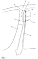
- FIG. 1 schematically shows a device 1 for ventilation of a rear Side window 11 of a vehicle 2 in connection with a B-pillar 3 of vehicle 2 shown schematically.
- FIG. 2 is in the area between the frame part 4 and the cladding part 6 has an air duct 7 with a rectangular cross section provided, which is shown schematically in at least one in FIG. 1 Impact area 8 is partially covered with a deformation sheet 9, so that the Air duct 7 in the impact area 8 together with the deformation plate 9 in a double function in addition to the conventional air routing function Deformation element 10 forms.
- the air duct 7 is in one lateral edge area of the frame part 4 assigned to the rear side window 11 arranged and screwed to it.
- the air duct 7 is a plastic blowing part with a closed profile formed, the air duct 7 in the B-pillar 3 approximately from Roof area downwards, preferably into the vehicle floor area extends, as can be seen in particular from FIG. 1.
- FIG. 2 It can further be seen from FIG. 2 that an outlet nozzle 12 in the Air duct 7 through cranked duct wall areas as nozzle walls 13, 14 is formed. As can be seen from the illustration in FIG. 2, the Air duct 7 in the area forming the nozzle walls 13, 14 not with the Deformation sheet 9 covered.
- FIG. 3 which shows the detail R of FIG shows an enlarged view
- elastomer seal 15, 16 is on the end of the nozzle walls 13, 14 of the outlet nozzle 12 each have an elastomer seal 15, 16 attached.
- the elastomer seal is there 15 of the nozzle wall 13 at an edge region of the trim part 6 and the Elastomer seal 16 of the nozzle wall 14 on a panel 17 on the frame part 4.
- the Elastomer seals 15, 16 are also below one in the assembled state Preload on the assigned components in order to achieve the best possible To enable sealing in connection with a possible tolerance compensation.
- FIG. 4 shows an alternative embodiment of the sealing arrangement according to FIG. 3 shown, here on the nozzle walls 13, 14 additional end-side abutment ribs 18, 19 are formed, on which foam seals 20, 21 are supported.
- This Foam seals 20, 21 are preferably both with the contact ribs 18, 19th as well as glued to the nozzle walls 13, 14 and are also under one Preload on the assigned components of the device 1.
Landscapes
- Physics & Mathematics (AREA)
- Thermal Sciences (AREA)
- Engineering & Computer Science (AREA)
- Mechanical Engineering (AREA)
- Air-Conditioning For Vehicles (AREA)
Description
- Fig. 1 eine
- schematische Darstellung eines in einer B-Säule verlaufenden Luftzuführkanals,
- Fig. 2
- einen schematischen Querschnitt durch die B-Säule entlang der Linie A-A der Fig. 1,
- Fig. 3
- eine vergrößerte Detailansicht der Einzelheit R der Fig. 2 und
- Fig. 4
- eine alternative Ausführungsform zu der in der Fig. 3 dargestellten Einzelheit R.
- 1
- Vorrichtung
- 2
- Fahrzeug
- 3
- B-Säule
- 4
- Rahmenteil
- 5
- Fahrzeuginnenraum
- 6
- Verkleidungsteil
- 7
- Luftführungskanal
- 8
- Aufprallbereich
- 9
- Deformationsblech
- 10
- Deformationselement
- 11
- Seitenscheibe
- 12
- Auslassdüse
- 13
- Düsenwand
- 14
- Düsenwand
- 15
- Elastomerdichtung
- 16
- Elastomerdichtung
- 17
- Blende
- 18
- Anlagerippe
- 19
- Anlagerippe
- 20
- Schaumstoffdichtung
- 21
- Schaumstoffdichtung
- 22
- Deformationsblech
- 23
- Gurthöhenverstelleinrichtung
Claims (13)
- Vorrichtung (1) zur Belüftung von Fahrzeugscheiben in einem Fahrzeug, mit einem in einem Scheibenbereich verlaufenden Rahmenteil (4) einer Fahrzeugkarosserie, das zum Innenraum (5) hin mit einem Verkleidungsteil (6) abdeckbar ist, wobei im Bereich zwischen dem Rahmenteil und dem Verkleidungsteil ein Luftführungskanal (7) vorgesehen ist, der mit einem energieabsorbierenden Element (9) gekoppelt ist, und wobei wenigstens eine in Richtung auf eine zugeordnete Fahrzeugscheibe gerichtete Auslassdüse (12) vorgesehen ist,
dadurch gekennzeichnet, dass das energieabsorbierende Element durch ein Deformationsblech (9) gebildet ist, mit dem der Luftführungskanal (7) wenigstens in einem Aufprallbereich (8) wenigstens teilweise ummantelt ist dergestalt, dass der Luftführungskanal (7) im Aufprallbereich zusammen mit dem Deformationsblech (9) ein Deformationselement (10) ausbildet, und
dass der Luftführungskanal (7) durch ein Kunststoff-Blasteil mit einem geschlossenen Profil gebildet ist. - Vorrichtung nach Anspruch 1, dadurch gekennzeichnet, dass der Luftführungskanal (7) in einem seitlichen, der Fahrzeugscheibe (11) zugeordneten Randbereich des Rahmenteils (4) angeordnet ist, und dass der Luftführungskanal (7) zusammen mit dem Deformationsblech (9) lösbar mit dem Rahmenteil (4) verbindbar ist.
- Vorrichtung nach Anspruch 1 oder Anspruch 2, dadurch gekennzeichnet, dass der Luftführungskanal (7) mit einer Luftzuführ- und/oder einer Luftabsaugleitung einer Belüftungs- und/oder Absaugeinrichtung gekoppelt ist.
- Vorrichtung nach einem der Ansprüche 1 bis 3, dadurch gekennzeichnet, dass die wenigstens eine Auslassdüse (12) im Luftführungskanal (7) durch abgekröpfte Führungskanalwandbereiche als Düsenwände (13, 14) gebildet ist.
- Vorrichtung nach Anspruch 4, dadurch gekennzeichnet, dass endseitig an den Düsenwänden (13, 14) jeweils ein Dichtelement (15, 16; 20, 21) vorgesehen ist, über die die Auslassdüse (12) und damit der Luftführungskanal (7) gegenüber dem Rahmenteil (4) und/oder dem Verkleidungsteil (6) abdichtbar ist.
- Vorrichtung nach Anspruch 5, dadurch gekennzeichnet, dass das Dichtelement (15, 16; 20, 21) unter Vorspannung am Rahmenteil (4) und/oder am Verkleidungsteil (6) anliegt.
- Vorrichtung nach Anspruch 5 oder Anspruch 6, dadurch gekennzeichnet, dass das Dichtelement (15, 16) auf die Düsenwände aufsteckbar ist.
- Vorrichtung nach Anspruch 5 oder Anspruch 6, dadurch gekennzeichnet, dass an den Düsenwänden (13, 14) endseitig Anlagerippen (18, 19) für damit und/oder mit den Düsenwänden (13, 14) verbindbare Dichtelemente (20, 21) angeordnet sind.
- Vorrichtung nach einem der Ansprüche 1 bis 8, dadurch gekennzeichnet, dass im Bereich jeder Auslassdüse (12) wenigstens eine Blende (17) zur gezielten Luftströmung angeordnet ist.
- Vorrichtung nach Anspruch 9, dadurch gekennzeichnet, dass die Blende (17) am Rahmenteil (4) und/oder am Verkleidungsteil (6) und/oder am Luftführungskanal (7) gehaltert ist.
- Vorrichtung nach einem der Ansprüche 1 bis 10, dadurch gekennzeichnet, dass das Rahmenteil (4) Bestandteil einer B-Säule (3) eines Kraftfahrzeugs (2) ist und die wenigstens eine Auslassdüse (12) auf eine dieser B-Säule (3) benachbarte hintere Seitenscheibe (11) gerichtet ist.
- Vorrichtung nach Anspruch 11, dadurch gekennzeichnet, dass der Luftführungskanal (7) in der B-Säule (3) in etwa vom Dachbereich ausgehend nach unten geführt ist, und dass der Luftführungskanal (7) im oberen Bereich wenigstens teilweise oder bereichsweise mit dem Deformationsblech (9) ummantelt ist.
- Vorrichtung nach einem der Ansprüche 1 bis 12, dadurch gekennzeichnet, dass das Deformationsblech (9) eine Stärke von in etwa 0,7 mm aufweist.
Applications Claiming Priority (3)
| Application Number | Priority Date | Filing Date | Title |
|---|---|---|---|
| DE10007402A DE10007402A1 (de) | 2000-02-18 | 2000-02-18 | Vorrichtung zur Belüftung von Fahrzeugscheiben in einem Fahrzeug |
| DE10007402 | 2000-02-18 | ||
| PCT/EP2001/001074 WO2001060647A1 (de) | 2000-02-18 | 2001-02-01 | Vorrichtung zur belüftung von fahrzeugscheiben in einem fahrzeug |
Publications (2)
| Publication Number | Publication Date |
|---|---|
| EP1263618A1 EP1263618A1 (de) | 2002-12-11 |
| EP1263618B1 true EP1263618B1 (de) | 2003-10-22 |
Family
ID=7631408
Family Applications (1)
| Application Number | Title | Priority Date | Filing Date |
|---|---|---|---|
| EP01919250A Expired - Lifetime EP1263618B1 (de) | 2000-02-18 | 2001-02-01 | Vorrichtung zur belüftung von fahrzeugscheiben in einem fahrzeug |
Country Status (4)
| Country | Link |
|---|---|
| EP (1) | EP1263618B1 (de) |
| AU (1) | AU2001246410A1 (de) |
| DE (2) | DE10007402A1 (de) |
| WO (1) | WO2001060647A1 (de) |
Cited By (2)
| Publication number | Priority date | Publication date | Assignee | Title |
|---|---|---|---|---|
| DE102005043290B3 (de) * | 2005-09-09 | 2007-05-24 | Ford Global Technologies, LLC, Dearborn | Lüftungssystem für die Scheiben und die Passagiersitze eines Fahrzeugs |
| DE102015012158A1 (de) * | 2015-09-16 | 2017-03-16 | Audi Ag | Belüftungsvorrichtung zum Belüften einer Fahrzeugtür, Fahrzeugtür und Kraftfahrzeug mit einer Fahrzeugtür |
Families Citing this family (1)
| Publication number | Priority date | Publication date | Assignee | Title |
|---|---|---|---|---|
| US7247088B2 (en) | 2003-09-25 | 2007-07-24 | Mazda Motor Corporation | Air conditioner for vehicle |
Family Cites Families (4)
| Publication number | Priority date | Publication date | Assignee | Title |
|---|---|---|---|---|
| JPS5822745A (ja) * | 1981-08-05 | 1983-02-10 | Nissan Motor Co Ltd | 窓ガラスの曇り止め装置 |
| DE4202256C2 (de) * | 1992-01-28 | 1994-11-03 | Beneform Gmbh | Luftkanalanordnung für die Lüftung oder Klimatisierung eines Fahrzeuginnenraumes sowie Verfahren zur Herstellung einer Luftkanalanordnung |
| US5591078A (en) * | 1995-09-29 | 1997-01-07 | Davidson Textron Inc. | Automotive interior trim having integrated defrost duct |
| JP3065584B2 (ja) * | 1998-06-03 | 2000-07-17 | 株式会社オーツカ | 衝撃エネルギーを吸収するエアダクト |
-
2000
- 2000-02-18 DE DE10007402A patent/DE10007402A1/de not_active Withdrawn
-
2001
- 2001-02-01 AU AU2001246410A patent/AU2001246410A1/en not_active Abandoned
- 2001-02-01 WO PCT/EP2001/001074 patent/WO2001060647A1/de not_active Ceased
- 2001-02-01 EP EP01919250A patent/EP1263618B1/de not_active Expired - Lifetime
- 2001-02-01 DE DE50100835T patent/DE50100835D1/de not_active Expired - Lifetime
Cited By (3)
| Publication number | Priority date | Publication date | Assignee | Title |
|---|---|---|---|---|
| DE102005043290B3 (de) * | 2005-09-09 | 2007-05-24 | Ford Global Technologies, LLC, Dearborn | Lüftungssystem für die Scheiben und die Passagiersitze eines Fahrzeugs |
| DE102015012158A1 (de) * | 2015-09-16 | 2017-03-16 | Audi Ag | Belüftungsvorrichtung zum Belüften einer Fahrzeugtür, Fahrzeugtür und Kraftfahrzeug mit einer Fahrzeugtür |
| DE102015012158B4 (de) | 2015-09-16 | 2019-10-02 | Audi Ag | Belüftungsvorrichtung zum Belüften einer Fahrzeugtür, Fahrzeugtür und Kraftfahrzeug mit einer Fahrzeugtür |
Also Published As
| Publication number | Publication date |
|---|---|
| AU2001246410A1 (en) | 2001-08-27 |
| DE50100835D1 (de) | 2003-11-27 |
| EP1263618A1 (de) | 2002-12-11 |
| WO2001060647A1 (de) | 2001-08-23 |
| DE10007402A1 (de) | 2001-08-23 |
Similar Documents
| Publication | Publication Date | Title |
|---|---|---|
| EP2050600B1 (de) | Entlüftungsvorrichtung | |
| DE69301923T2 (de) | Querteil für ein armaturenbrett für ein kraftfahrzeug | |
| DE69627772T2 (de) | Innenbekleidung für Kraftfahrzeuge mit integrierter Luftkanal | |
| DE3003216C2 (de) | ||
| EP2481644B1 (de) | Anordnung einer Instrumententafel im Innenraum eines Kraftfahrzeuges | |
| EP3765351B1 (de) | Verkleidungseinrichtung für einen seitenschweller eines personenkraftwagens sowie verfahren zum betreiben einer derartigen verkleidungseinrichtung | |
| DE3840214A1 (de) | Lufteinlassgehaeuse fuer ein kraftfahrzeug | |
| DE19812489C1 (de) | Belüftungseinrichtung für eine Seitenscheibe eines Kraftfahrzeuges | |
| EP0716946A1 (de) | Windabweiser für Schiebedächer an Kraftfahrzeugen | |
| EP1840002B1 (de) | Kraftfahrzeug mit einem Deformationselement zur Aufnahme von Seitenaufprallkräften im Seitenbereich des Kraftfahrzeuges | |
| DE102008060410B4 (de) | Kraftfahrzeug mit Schwellerblende | |
| DE112014000458B4 (de) | Front-Karosseriestruktur eines Kraftfahrzeugs | |
| EP2284048A1 (de) | Verkleidungsteil mit Airbagklappenanordnung im Innenraum eines Kraftfahrzeuges | |
| EP3250405B1 (de) | Windleiteinrichtung für einen offenen personenkraftwagen | |
| WO2011091971A1 (de) | Vorderwagen eines fahrzeugs | |
| EP0655357A1 (de) | Heizungs-, Belüftungs und/oder Klimatisierungsvorrichtung | |
| EP1045769B1 (de) | Lufteintritt für eine heizungs- oder klimaanlage eines kraftfahrzeuges | |
| DE10347847B3 (de) | Kraftwagenkarosserie mit zentraler Tragsäule | |
| EP1762406B1 (de) | Fahrzeug mit einem Lüftungssystem für die Scheiben und die Passagiersitze | |
| EP1263618A1 (de) | Vorrichtung zur belüftung von fahrzeugscheiben in einem fahrzeug | |
| DE102004005481A1 (de) | Lüftungssystem | |
| DE102005015203B4 (de) | Fahrzeugdach mit einer Dachhaut und einer formstabilen Verkleidungsschale | |
| DE10353823B4 (de) | Belüftungseinrichtung für einen Fahrzeuginnenraum eines Fahrzeuges, insbesondere eines Nutzfahrzeuges | |
| DE10362300B4 (de) | Belüftungseinrichtung für einen Fahrzeuginnenraum eines Fahrzeuges, insbesondere eines Nutzfahrzeuges | |
| DE19849489C1 (de) | Rohbaukarosserie für ein Kraftfahrzeug |
Legal Events
| Date | Code | Title | Description |
|---|---|---|---|
| PUAI | Public reference made under article 153(3) epc to a published international application that has entered the european phase |
Free format text: ORIGINAL CODE: 0009012 |
|
| 17P | Request for examination filed |
Effective date: 20020918 |
|
| AK | Designated contracting states |
Kind code of ref document: A1 Designated state(s): AT BE CH CY DE DK ES FI FR GB GR IE IT LI LU MC NL PT SE TR |
|
| AX | Request for extension of the european patent |
Free format text: AL;LT;LV;MK;RO;SI |
|
| 17Q | First examination report despatched |
Effective date: 20030203 |
|
| GRAH | Despatch of communication of intention to grant a patent |
Free format text: ORIGINAL CODE: EPIDOS IGRA |
|
| GRAA | (expected) grant |
Free format text: ORIGINAL CODE: 0009210 |
|
| GRAS | Grant fee paid |
Free format text: ORIGINAL CODE: EPIDOSNIGR3 |
|
| AK | Designated contracting states |
Kind code of ref document: B1 Designated state(s): DE FR GB IT |
|
| PG25 | Lapsed in a contracting state [announced via postgrant information from national office to epo] |
Ref country code: IT Free format text: LAPSE BECAUSE OF FAILURE TO SUBMIT A TRANSLATION OF THE DESCRIPTION OR TO PAY THE FEE WITHIN THE PRESCRIBED TIME-LIMIT;WARNING: LAPSES OF ITALIAN PATENTS WITH EFFECTIVE DATE BEFORE 2007 MAY HAVE OCCURRED AT ANY TIME BEFORE 2007. THE CORRECT EFFECTIVE DATE MAY BE DIFFERENT FROM THE ONE RECORDED. Effective date: 20031022 Ref country code: GB Free format text: LAPSE BECAUSE OF FAILURE TO SUBMIT A TRANSLATION OF THE DESCRIPTION OR TO PAY THE FEE WITHIN THE PRESCRIBED TIME-LIMIT Effective date: 20031022 Ref country code: FR Free format text: LAPSE BECAUSE OF FAILURE TO SUBMIT A TRANSLATION OF THE DESCRIPTION OR TO PAY THE FEE WITHIN THE PRESCRIBED TIME-LIMIT Effective date: 20031022 |
|
| REG | Reference to a national code |
Ref country code: GB Ref legal event code: FG4D Free format text: NOT ENGLISH |
|
| REG | Reference to a national code |
Ref country code: IE Ref legal event code: FG4D Free format text: GERMAN |
|
| REF | Corresponds to: |
Ref document number: 50100835 Country of ref document: DE Date of ref document: 20031127 Kind code of ref document: P |
|
| LTIE | Lt: invalidation of european patent or patent extension |
Effective date: 20031022 |
|
| GBV | Gb: ep patent (uk) treated as always having been void in accordance with gb section 77(7)/1977 [no translation filed] |
Effective date: 20031022 |
|
| REG | Reference to a national code |
Ref country code: IE Ref legal event code: FD4D |
|
| PLBE | No opposition filed within time limit |
Free format text: ORIGINAL CODE: 0009261 |
|
| STAA | Information on the status of an ep patent application or granted ep patent |
Free format text: STATUS: NO OPPOSITION FILED WITHIN TIME LIMIT |
|
| 26N | No opposition filed |
Effective date: 20040723 |
|
| EN | Fr: translation not filed | ||
| PGFP | Annual fee paid to national office [announced via postgrant information from national office to epo] |
Ref country code: DE Payment date: 20170228 Year of fee payment: 17 |
|
| REG | Reference to a national code |
Ref country code: DE Ref legal event code: R119 Ref document number: 50100835 Country of ref document: DE |
|
| PG25 | Lapsed in a contracting state [announced via postgrant information from national office to epo] |
Ref country code: DE Free format text: LAPSE BECAUSE OF NON-PAYMENT OF DUE FEES Effective date: 20180901 |