EP1263267A2 - Verfahren zum Start einer Entladungslampe - Google Patents
Verfahren zum Start einer Entladungslampe Download PDFInfo
- Publication number
- EP1263267A2 EP1263267A2 EP02005924A EP02005924A EP1263267A2 EP 1263267 A2 EP1263267 A2 EP 1263267A2 EP 02005924 A EP02005924 A EP 02005924A EP 02005924 A EP02005924 A EP 02005924A EP 1263267 A2 EP1263267 A2 EP 1263267A2
- Authority
- EP
- European Patent Office
- Prior art keywords
- lamp
- electrode
- phase
- preheated
- electrode coil
- Prior art date
- Legal status (The legal status is an assumption and is not a legal conclusion. Google has not performed a legal analysis and makes no representation as to the accuracy of the status listed.)
- Granted
Links
Images
Classifications
-
- H—ELECTRICITY
- H05—ELECTRIC TECHNIQUES NOT OTHERWISE PROVIDED FOR
- H05B—ELECTRIC HEATING; ELECTRIC LIGHT SOURCES NOT OTHERWISE PROVIDED FOR; CIRCUIT ARRANGEMENTS FOR ELECTRIC LIGHT SOURCES, IN GENERAL
- H05B41/00—Circuit arrangements or apparatus for igniting or operating discharge lamps
- H05B41/14—Circuit arrangements
- H05B41/26—Circuit arrangements in which the lamp is fed by power derived from DC by means of a converter, e.g. by high-voltage DC
- H05B41/28—Circuit arrangements in which the lamp is fed by power derived from DC by means of a converter, e.g. by high-voltage DC using static converters
- H05B41/295—Circuit arrangements in which the lamp is fed by power derived from DC by means of a converter, e.g. by high-voltage DC using static converters with semiconductor devices and specially adapted for lamps with preheating electrodes, e.g. for fluorescent lamps
Definitions
- the invention is based on a method according to the preamble of the claim 1. This is, in particular, a method for starting a discharge lamp.
- Lamps are often called electrodes, which act as electrode filaments are executed.
- Preheating is important for the following reason: Is an electrode coil cold then it forms for the emission of electrons, i.e. for the If it acts as a cathode, a high cathode drop. This cathode case causes a rapid acceleration of incoming mercury ions. Those striking the electrode coil with high energy Mercury ions lead to rapid wear of the electrode coil and therefore a short lamp life.
- the preheating is therefore a quality feature for a high-quality electronic Control gear.
- the circuitry means implementation the preheating a considerable effort, which is a substantial part of the Costs of the control gear.
- Preheating is complicated by the fact that the electrode coils to be heated lie on different sides of the lamp. That is, the circuit parts for heating the two electrode coils must be designed so that they allow an ignition voltage on the lamp and survive it undamaged.
- the object of the present invention is a method according to the preamble of claim 1 to provide with a simple and inexpensive preheating the electrode filaments of a discharge lamp is possible.
- Electrode filaments of a lamp preheated only one of the two is used to reduce the circuit complexity Electrode filaments of a lamp preheated.
- an electrode coil is used only damaged if it is cold and currently acts as a cathode.
- the ignition will take place when the one The electrode is currently the cathode, which has been preheated because in this state the the voltage required for ignition is the lowest.
- the ignition process itself thus no damage to the electrode coil not preheated according to the invention.
- Ignition with DC voltage is also possible, but this does not preheated electrode coil acts as an anode. In this case, too Ignition process for no damage to the electrode coil not preheated according to the invention.
- a non-preheated electrode coil is used always damaged if it is currently a cathode.
- the operation of the lamp is therefore divided into two sub-phases.
- the lamp is operated according to the invention with direct current applied, the non-preheated electrode coil acting as an anode.
- the anode is not exposed to the bombardment of mercury ions, it will not damaged even if it has not been preheated.
- Electron bombardment heats up an anode during lamp operation.
- D. H. The non-preheated electrode coil is in the first sub-phase of operation heated.
- the first ends according to the invention Subphase of operations.
- the subsequent second sub-phase of the operation AC lamp applied to the lamp.
- the second subphase corresponds to that Normal operation of the lamp as prescribed in relevant standards (e.g. IEC81) is.
- the first subphase according to the invention is of such a short duration that the segregation effects mentioned above do not occur.
- the non-preheated electrode coil operated as an anode at a temperature level, which allows damage-free operation as a cathode.
- the preheating according to the invention leads to only one electrode coil to a significant reduction in circuitry. Since you are in the choice of the electrode coil that is preheated is free, you become one
- Preheat the electrode coil which has the least amount of circuitry due to its reference to ground requires. Preheating the electrode coil without reference to ground generally requires more circuitry. This can, however, according to the invention omitted.
- the advantage of the present invention lies not only in the reduction of the Circuit effort but also in a reduction of the effort for connection the lamp.
- a lamp with two electrode filaments usually has four Connections. If both electrode coils are preheated, four connecting wires must be used be laid to the lamp. However, according to the invention only one Electrode coil preheated, three connecting wires are sufficient. Just the electrode coil, which is preheated is connected at its two connections. For the non-preheated electrode coil is sufficient for one connecting wire.
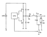
- FIG. 1 shows the basic circuit diagram of an electronic control gear, with which the inventive method can be carried out.
- An AC voltage generator which is designed as a half-bridge inverter, forms the core of the electronic control gear. It consists of the series connection of the electronic half-bridge switches S1 and S2, which are controlled by a control unit CTR.
- the series connection of the electronic half-bridge switches S1 and S2 is connected to a DC voltage source UDC for energy supply.
- the reference potential is the potential M, which is connected to the negative pole of the DC voltage source UDC.
- a free-wheeling diode D1 and D2 is connected in parallel with each half-bridge switch S1 and S2. They are polarized so that the cathode points in the direction of the positive pole of the DC voltage source.
- the load circuit is connected between the source voltage Uq and the reference potential M. It consists of a series connection of a coupling capacitor Cb, an inductor L, a capacitor C and an electronic heating control switch S3.
- the coupling capacitor Cb serves to decouple the DC component of the source voltage Uq .
- the inductance L and the capacitance C form a series resonance with the resonance frequency fres .
- the output of the load circuit, to which a lamp Lp is connected, is parallel to the capacitance C. A lamp voltage ULp is also tapped there.
- the lamp has two filaments W1 and W2, each with two connections.
- the lamp is connected to the capacitance C so that a connection of the electrode filament W1 is connected to a connector of capacitance C and a connector the electrode coil W2 is connected to the other connection of the capacitance C. is.
- the other connection of the electrode coil W1 remains unconnected according to the invention.
- the other connection of the electrode coil W2 is with the reference potential M connected.
- the control unit CTR also controls the heating control switch S3. This doesn't have to can be designed for the ignition voltage of the lamp Lp of several hundred volts. Rather, a dielectric strength of up to 50 volts is sufficient.
- the half-bridge switches S1 and S2 alternate with one high preheating frequency on and off.
- the heating control switch S3 is open.
- the electrode coil W2 is preheated via the capacitance C.
- the preheating frequency must be selected so high that the capacitance C is activated sets a sufficiently high preheating current, which turns the electrode filament in about one second W2 heats up to a temperature that is largely damage-free Ignition allowed.
- the heating control switch S3 is closed and the frequency with which the half-bridge switches S1 and S2 are switched on and off alternately up to the resonance frequency of the series resonant circuit, consisting of the inductance L and the capacitance C. This builds on the lamp Lp an ignition voltage that leads to the ignition of the lamp.
- the half-bridge switch remains S2 opened and only the half-bridge switch S1 is switched on and off.
- the non-preheated electrode coil W1 acts as an anode. It is on it to ensure that the value of the capacitance of the coupling capacitor Cb is chosen so large is that the voltage across the coupling capacitor Cb during the first subphase of operations does not change significantly.
- the second sub-phase of operation begins after a maximum of 2 seconds.
- the half-bridge switches S1 and S2 are switched on and off alternately. As a result, an alternating current is supplied to the lamp Lp.
- the heating control switch S3 remains closed during the operating phase. In order to is achieved that no heating current through the electrode coil during the operating phase W2 flows through. This will cause the filament W2 to overheat avoided and the efficiency of the control gear increased. Through the electrode coil According to the invention, current never flows through W1.
Landscapes
- Circuit Arrangements For Discharge Lamps (AREA)
Abstract
Description
Claims (5)
- Verfahren zum Start einer Entladungslampe mit zwei vorheizbaren Elektrodenwendeln, welches in die folgenden drei Phasen unterteilt werden kann:dadurch gekennzeichnet, dass in der Phase Vorheizen nur eine Elektroden-Wendel vorgeheizt wird und die Phase Betrieb in zwei Subphasen eingeteilt ist, wobei in der ersten Subphase Gleichstrom und in der zweiten Subphase Wechselstrom durch die Entladungslampe fließt.VorheizenZündenBetrieb,
- Verfahren gemäß Anspruch 1, dadurch gekennzeichnet, dass die erste Subphase eine Dauer aufweist, die zwischen 0,1 Sekunde und 2 Sekunden liegt.
- Verfahren gemäß Anspruch 1, dadurch gekennzeichnet, dass während der Phase Zünden Gleich- oder Wechselspannung an der Lampe anliegen.
- Betriebsgerät zum Betrieb von Entladungslampen mit Elektrodenwendeln (W1, W2) mit einem Wechselspannungsgenerator, der als Halbbrückenwechselrichter mit elektronischen Halbbrückenschaltern (S1, S2) ausgeführt ist, dadurch gekennzeichnet, dass der Betrieb der Lampen eine Subphase beinhaltet, in der ein Halbbrückenschalter (S2) für mindestens 0,1 Sekunden geöffnet bleibt.
- Betriebsgerät gemäß Anspruch 4, dadurch gekennzeichnet, dass zwei Wendelanschlüsse einer Elektrodenwendel (W2) während des Betriebs einer Lampe über einen Heizsteuer-Schalter (S3) kurzgeschlossen sind.
Applications Claiming Priority (2)
| Application Number | Priority Date | Filing Date | Title |
|---|---|---|---|
| DE10126011A DE10126011A1 (de) | 2001-05-28 | 2001-05-28 | Verfahren zum Start einer Entladungslampe |
| DE10126011 | 2001-05-28 |
Publications (3)
| Publication Number | Publication Date |
|---|---|
| EP1263267A2 true EP1263267A2 (de) | 2002-12-04 |
| EP1263267A3 EP1263267A3 (de) | 2005-06-01 |
| EP1263267B1 EP1263267B1 (de) | 2007-05-02 |
Family
ID=7686444
Family Applications (1)
| Application Number | Title | Priority Date | Filing Date |
|---|---|---|---|
| EP02005924A Expired - Lifetime EP1263267B1 (de) | 2001-05-28 | 2002-03-14 | Verfahren zum Start einer Entladungslampe |
Country Status (4)
| Country | Link |
|---|---|
| US (1) | US6696791B2 (de) |
| EP (1) | EP1263267B1 (de) |
| CA (1) | CA2383335A1 (de) |
| DE (2) | DE10126011A1 (de) |
Families Citing this family (6)
| Publication number | Priority date | Publication date | Assignee | Title |
|---|---|---|---|---|
| CN1874645B (zh) * | 2005-05-31 | 2010-09-29 | 电灯专利信托有限公司 | 用于将灯安全连接到设备地的装置 |
| US7560868B2 (en) * | 2007-05-11 | 2009-07-14 | Osram Sylvania, Inc. | Ballast with filament heating and ignition control |
| US8217583B2 (en) * | 2010-07-21 | 2012-07-10 | Grenergy Opto, Inc. | Gas-discharge lamp controller utilizing a novel reheating frequency generation mechanism |
| US8471475B1 (en) * | 2010-07-23 | 2013-06-25 | Universal Lighting Technologies, Inc. | Modular dimming ballast with decoupled half-bridge topology |
| US8847512B1 (en) * | 2010-10-29 | 2014-09-30 | Universal Lighting Technologies, Inc. | Program start ballast having resonant filament heating circuit with clamped quality factor |
| US9237636B1 (en) | 2014-05-12 | 2016-01-12 | Universal Lighting Technologies, Inc. | Self-clamped resonant filament heating circuit |
Family Cites Families (8)
| Publication number | Priority date | Publication date | Assignee | Title |
|---|---|---|---|---|
| DE2854829A1 (de) * | 1978-12-19 | 1980-07-10 | Nemectron Gmbh | Zuendschaltung fuer eine gasentladungslampe |
| US5170099A (en) * | 1989-03-28 | 1992-12-08 | Matsushita Electric Works, Ltd. | Discharge lamp lighting device |
| DE4014355A1 (de) * | 1989-06-27 | 1991-01-03 | Siemens Ag | Elektronisches vorschaltgeraet fuer leuchtstofflampen |
| US5656891A (en) * | 1994-10-13 | 1997-08-12 | Tridonic Bauelemente Gmbh | Gas discharge lamp ballast with heating control circuit and method of operating same |
| DE19509832A1 (de) * | 1995-03-17 | 1996-09-19 | Patent Treuhand Ges Fuer Elektrische Gluehlampen Mbh | Verfahren und Schaltungsanordnung zum Betrieb einer Entladungslampe |
| JP3736171B2 (ja) * | 1998-03-31 | 2006-01-18 | 東芝ライテック株式会社 | 電球形蛍光ランプ及び照明器具 |
| JP2002500819A (ja) * | 1998-04-02 | 2002-01-08 | コーニンクレッカ フィリップス エレクトロニクス エヌ ヴィ | 回路装置 |
| EP1103166B1 (de) * | 1999-05-25 | 2003-07-16 | TridonicAtco GmbH & Co. KG | Elektronisches vorschaltgerät für mindestens eine niederdruck-entladungslampe |
-
2001
- 2001-05-28 DE DE10126011A patent/DE10126011A1/de not_active Withdrawn
-
2002
- 2002-03-14 EP EP02005924A patent/EP1263267B1/de not_active Expired - Lifetime
- 2002-03-14 DE DE50210057T patent/DE50210057D1/de not_active Expired - Lifetime
- 2002-04-11 US US10/119,746 patent/US6696791B2/en not_active Expired - Fee Related
- 2002-04-25 CA CA002383335A patent/CA2383335A1/en not_active Abandoned
Also Published As
| Publication number | Publication date |
|---|---|
| EP1263267A3 (de) | 2005-06-01 |
| US6696791B2 (en) | 2004-02-24 |
| CA2383335A1 (en) | 2002-11-28 |
| DE10126011A1 (de) | 2002-12-05 |
| DE50210057D1 (de) | 2007-06-14 |
| US20020175629A1 (en) | 2002-11-28 |
| EP1263267B1 (de) | 2007-05-02 |
Similar Documents
| Publication | Publication Date | Title |
|---|---|---|
| DE3319739C2 (de) | Vorschaltgerät für Gasentladungslampen | |
| EP0239793B1 (de) | Schaltungsanordnung zum Betrieb von Niederdruckentladungslampen | |
| DE3221701A1 (de) | Schaltungsanordnung zum starten und betreiben von leuchtstofflampen | |
| EP0062276A1 (de) | Vorschaltanordnung zum Betreiben von Niederdruckentladungslampen | |
| DE19729768B4 (de) | Schaltungsanordnung zum Zünden und Betreiben einer Leuchtstofflampe | |
| EP1741320B1 (de) | Schaltungsanordnung zum betrieb von hochdruckentladungslampen und betriebsverfahren für eine hochdruckentladungslampe | |
| EP0439240A2 (de) | Elektronisches Vorschaltgerät | |
| DE19517950A1 (de) | Stromversorgungseinrichtung | |
| DE3711814A1 (de) | Elektronisches vorschaltgeraet zum betrieb von leuchtstofflampen | |
| EP1263267B1 (de) | Verfahren zum Start einer Entladungslampe | |
| DE19830368A1 (de) | Elektronisches Vorschaltgerät mit Einschaltstrombegrenzung | |
| EP1869951A1 (de) | Hochdruckgasentladungslampeimpulszündvorrichtung mit piezoelektrischem transformator | |
| EP1938670B1 (de) | Elektronisches vorschaltgerät und verfahren zum betreiben einer elektrischen lampe | |
| EP2274960B1 (de) | Verfahren und schaltungsanordnung zum betreiben mindestens einer entladungslampe | |
| EP0697803A2 (de) | Schaltungsanordnung zur Ansteuerung von Gasentladungslampen | |
| DE69714163T2 (de) | Schaltungsanordnung | |
| EP1028606A2 (de) | Schaltungsanordnung zum Betrieb mindestens einer Niederdruckentladungslampe | |
| EP1590993B1 (de) | Elektronisches vorschaltgerät | |
| EP1225792A1 (de) | Betriebsgerät für Entladungslampen mit Abschaltung der Elektrodenwendelheizung | |
| DE4227427C2 (de) | Verfahren und Schaltungsanordnung zum Zünden von Entladungslampen | |
| WO2006122526A1 (de) | Schaltungsanordnung zum betrieb einer entladungslampe mit schaltbarem resonanzkondensator | |
| DE102005057107B4 (de) | Vorschaltgerät | |
| EP0794695B1 (de) | Schaltung zum Betrieb einer Hochdruckgasentladungslampe | |
| DE3503778C2 (de) | Leuchtstofflampen-Vorschaltgerät | |
| EP1583403A1 (de) | Vorschaltgerät für mindestens eine Lampe |
Legal Events
| Date | Code | Title | Description |
|---|---|---|---|
| PUAI | Public reference made under article 153(3) epc to a published international application that has entered the european phase |
Free format text: ORIGINAL CODE: 0009012 |
|
| AK | Designated contracting states |
Kind code of ref document: A2 Designated state(s): AT BE CH CY DE DK ES FI FR GB GR IE IT LI LU MC NL PT SE TR |
|
| AX | Request for extension of the european patent |
Free format text: AL;LT;LV;MK;RO;SI |
|
| PUAL | Search report despatched |
Free format text: ORIGINAL CODE: 0009013 |
|
| AK | Designated contracting states |
Kind code of ref document: A3 Designated state(s): AT BE CH CY DE DK ES FI FR GB GR IE IT LI LU MC NL PT SE TR |
|
| AX | Request for extension of the european patent |
Extension state: AL LT LV MK RO SI |
|
| RIC1 | Information provided on ipc code assigned before grant |
Ipc: 7H 05B 41/295 A Ipc: 7H 05B 41/04 B |
|
| 17P | Request for examination filed |
Effective date: 20050620 |
|
| AKX | Designation fees paid |
Designated state(s): DE FR GB |
|
| GRAP | Despatch of communication of intention to grant a patent |
Free format text: ORIGINAL CODE: EPIDOSNIGR1 |
|
| GRAS | Grant fee paid |
Free format text: ORIGINAL CODE: EPIDOSNIGR3 |
|
| GRAA | (expected) grant |
Free format text: ORIGINAL CODE: 0009210 |
|
| AK | Designated contracting states |
Kind code of ref document: B1 Designated state(s): DE FR GB |
|
| REG | Reference to a national code |
Ref country code: GB Ref legal event code: FG4D Free format text: NOT ENGLISH |
|
| REF | Corresponds to: |
Ref document number: 50210057 Country of ref document: DE Date of ref document: 20070614 Kind code of ref document: P |
|
| GBT | Gb: translation of ep patent filed (gb section 77(6)(a)/1977) |
Effective date: 20070627 |
|
| ET | Fr: translation filed | ||
| PLBE | No opposition filed within time limit |
Free format text: ORIGINAL CODE: 0009261 |
|
| STAA | Information on the status of an ep patent application or granted ep patent |
Free format text: STATUS: NO OPPOSITION FILED WITHIN TIME LIMIT |
|
| 26N | No opposition filed |
Effective date: 20080205 |
|
| PGFP | Annual fee paid to national office [announced via postgrant information from national office to epo] |
Ref country code: FR Payment date: 20110321 Year of fee payment: 10 |
|
| PGFP | Annual fee paid to national office [announced via postgrant information from national office to epo] |
Ref country code: GB Payment date: 20110310 Year of fee payment: 10 |
|
| PG25 | Lapsed in a contracting state [announced via postgrant information from national office to epo] |
Ref country code: DE Free format text: LAPSE BECAUSE OF NON-PAYMENT OF DUE FEES Effective date: 20111001 |
|
| PGFP | Annual fee paid to national office [announced via postgrant information from national office to epo] |
Ref country code: DE Payment date: 20110520 Year of fee payment: 10 |
|
| GBPC | Gb: european patent ceased through non-payment of renewal fee |
Effective date: 20120314 |
|
| REG | Reference to a national code |
Ref country code: FR Ref legal event code: ST Effective date: 20121130 |
|
| REG | Reference to a national code |
Ref country code: DE Ref legal event code: R119 Ref document number: 50210057 Country of ref document: DE Effective date: 20121002 |
|
| PG25 | Lapsed in a contracting state [announced via postgrant information from national office to epo] |
Ref country code: FR Free format text: LAPSE BECAUSE OF NON-PAYMENT OF DUE FEES Effective date: 20120402 Ref country code: GB Free format text: LAPSE BECAUSE OF NON-PAYMENT OF DUE FEES Effective date: 20120314 |