EP1263267A2 - Method for starting a discharge lamp - Google Patents
Method for starting a discharge lamp Download PDFInfo
- Publication number
- EP1263267A2 EP1263267A2 EP02005924A EP02005924A EP1263267A2 EP 1263267 A2 EP1263267 A2 EP 1263267A2 EP 02005924 A EP02005924 A EP 02005924A EP 02005924 A EP02005924 A EP 02005924A EP 1263267 A2 EP1263267 A2 EP 1263267A2
- Authority
- EP
- European Patent Office
- Prior art keywords
- lamp
- electrode
- phase
- preheated
- discharge lamp
- Prior art date
- Legal status (The legal status is an assumption and is not a legal conclusion. Google has not performed a legal analysis and makes no representation as to the accuracy of the status listed.)
- Granted
Links
Images
Classifications
-
- H—ELECTRICITY
- H05—ELECTRIC TECHNIQUES NOT OTHERWISE PROVIDED FOR
- H05B—ELECTRIC HEATING; ELECTRIC LIGHT SOURCES NOT OTHERWISE PROVIDED FOR; CIRCUIT ARRANGEMENTS FOR ELECTRIC LIGHT SOURCES, IN GENERAL
- H05B41/00—Circuit arrangements or apparatus for igniting or operating discharge lamps
- H05B41/14—Circuit arrangements
- H05B41/26—Circuit arrangements in which the lamp is fed by power derived from dc by means of a converter, e.g. by high-voltage dc
- H05B41/28—Circuit arrangements in which the lamp is fed by power derived from dc by means of a converter, e.g. by high-voltage dc using static converters
- H05B41/295—Circuit arrangements in which the lamp is fed by power derived from dc by means of a converter, e.g. by high-voltage dc using static converters with semiconductor devices and specially adapted for lamps with preheating electrodes, e.g. for fluorescent lamps
Definitions
- the invention is based on a method according to the preamble of the claim 1. This is, in particular, a method for starting a discharge lamp.
- Lamps are often called electrodes, which act as electrode filaments are executed.
- Preheating is important for the following reason: Is an electrode coil cold then it forms for the emission of electrons, i.e. for the If it acts as a cathode, a high cathode drop. This cathode case causes a rapid acceleration of incoming mercury ions. Those striking the electrode coil with high energy Mercury ions lead to rapid wear of the electrode coil and therefore a short lamp life.
- the preheating is therefore a quality feature for a high-quality electronic Control gear.
- the circuitry means implementation the preheating a considerable effort, which is a substantial part of the Costs of the control gear.
- Preheating is complicated by the fact that the electrode coils to be heated lie on different sides of the lamp. That is, the circuit parts for heating the two electrode coils must be designed so that they allow an ignition voltage on the lamp and survive it undamaged.
- the object of the present invention is a method according to the preamble of claim 1 to provide with a simple and inexpensive preheating the electrode filaments of a discharge lamp is possible.
- Electrode filaments of a lamp preheated only one of the two is used to reduce the circuit complexity Electrode filaments of a lamp preheated.
- an electrode coil is used only damaged if it is cold and currently acts as a cathode.
- the ignition will take place when the one The electrode is currently the cathode, which has been preheated because in this state the the voltage required for ignition is the lowest.
- the ignition process itself thus no damage to the electrode coil not preheated according to the invention.
- Ignition with DC voltage is also possible, but this does not preheated electrode coil acts as an anode. In this case, too Ignition process for no damage to the electrode coil not preheated according to the invention.
- a non-preheated electrode coil is used always damaged if it is currently a cathode.
- the operation of the lamp is therefore divided into two sub-phases.
- the lamp is operated according to the invention with direct current applied, the non-preheated electrode coil acting as an anode.
- the anode is not exposed to the bombardment of mercury ions, it will not damaged even if it has not been preheated.
- Electron bombardment heats up an anode during lamp operation.
- D. H. The non-preheated electrode coil is in the first sub-phase of operation heated.
- the first ends according to the invention Subphase of operations.
- the subsequent second sub-phase of the operation AC lamp applied to the lamp.
- the second subphase corresponds to that Normal operation of the lamp as prescribed in relevant standards (e.g. IEC81) is.
- the first subphase according to the invention is of such a short duration that the segregation effects mentioned above do not occur.
- the non-preheated electrode coil operated as an anode at a temperature level, which allows damage-free operation as a cathode.
- the preheating according to the invention leads to only one electrode coil to a significant reduction in circuitry. Since you are in the choice of the electrode coil that is preheated is free, you become one
- Preheat the electrode coil which has the least amount of circuitry due to its reference to ground requires. Preheating the electrode coil without reference to ground generally requires more circuitry. This can, however, according to the invention omitted.
- the advantage of the present invention lies not only in the reduction of the Circuit effort but also in a reduction of the effort for connection the lamp.
- a lamp with two electrode filaments usually has four Connections. If both electrode coils are preheated, four connecting wires must be used be laid to the lamp. However, according to the invention only one Electrode coil preheated, three connecting wires are sufficient. Just the electrode coil, which is preheated is connected at its two connections. For the non-preheated electrode coil is sufficient for one connecting wire.
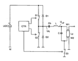
- FIG. 1 shows the basic circuit diagram of an electronic control gear, with which the inventive method can be carried out.
- An AC voltage generator which is designed as a half-bridge inverter, forms the core of the electronic control gear. It consists of the series connection of the electronic half-bridge switches S1 and S2, which are controlled by a control unit CTR.
- the series connection of the electronic half-bridge switches S1 and S2 is connected to a DC voltage source UDC for energy supply.
- the reference potential is the potential M, which is connected to the negative pole of the DC voltage source UDC.
- a free-wheeling diode D1 and D2 is connected in parallel with each half-bridge switch S1 and S2. They are polarized so that the cathode points in the direction of the positive pole of the DC voltage source.
- the load circuit is connected between the source voltage Uq and the reference potential M. It consists of a series connection of a coupling capacitor Cb, an inductor L, a capacitor C and an electronic heating control switch S3.
- the coupling capacitor Cb serves to decouple the DC component of the source voltage Uq .
- the inductance L and the capacitance C form a series resonance with the resonance frequency fres .
- the output of the load circuit, to which a lamp Lp is connected, is parallel to the capacitance C. A lamp voltage ULp is also tapped there.
- the lamp has two filaments W1 and W2, each with two connections.
- the lamp is connected to the capacitance C so that a connection of the electrode filament W1 is connected to a connector of capacitance C and a connector the electrode coil W2 is connected to the other connection of the capacitance C. is.
- the other connection of the electrode coil W1 remains unconnected according to the invention.
- the other connection of the electrode coil W2 is with the reference potential M connected.
- the control unit CTR also controls the heating control switch S3. This doesn't have to can be designed for the ignition voltage of the lamp Lp of several hundred volts. Rather, a dielectric strength of up to 50 volts is sufficient.
- the half-bridge switches S1 and S2 alternate with one high preheating frequency on and off.
- the heating control switch S3 is open.
- the electrode coil W2 is preheated via the capacitance C.
- the preheating frequency must be selected so high that the capacitance C is activated sets a sufficiently high preheating current, which turns the electrode filament in about one second W2 heats up to a temperature that is largely damage-free Ignition allowed.
- the heating control switch S3 is closed and the frequency with which the half-bridge switches S1 and S2 are switched on and off alternately up to the resonance frequency of the series resonant circuit, consisting of the inductance L and the capacitance C. This builds on the lamp Lp an ignition voltage that leads to the ignition of the lamp.
- the half-bridge switch remains S2 opened and only the half-bridge switch S1 is switched on and off.
- the non-preheated electrode coil W1 acts as an anode. It is on it to ensure that the value of the capacitance of the coupling capacitor Cb is chosen so large is that the voltage across the coupling capacitor Cb during the first subphase of operations does not change significantly.
- the second sub-phase of operation begins after a maximum of 2 seconds.
- the half-bridge switches S1 and S2 are switched on and off alternately. As a result, an alternating current is supplied to the lamp Lp.
- the heating control switch S3 remains closed during the operating phase. In order to is achieved that no heating current through the electrode coil during the operating phase W2 flows through. This will cause the filament W2 to overheat avoided and the efficiency of the control gear increased. Through the electrode coil According to the invention, current never flows through W1.
Landscapes
- Circuit Arrangements For Discharge Lamps (AREA)
Abstract
Description
Die Erfindung geht aus von einem Verfahren gemäß dem Oberbegriff des Anspruchs 1. Es handelt sich dabei insbesondere um ein Verfahren zum Start einer Entladungslampe.The invention is based on a method according to the preamble of the claim 1. This is, in particular, a method for starting a discharge lamp.
Entladungslampen, insbesondere Niederdruckentladungslampen, die im folgenden kurz Lampen genannt werden, besitzen häufig Elektroden, die als Elektroden-Wendeln ausgeführt sind.Discharge lamps, in particular low-pressure discharge lamps, as follows Lamps are often called electrodes, which act as electrode filaments are executed.
Im folgenden wird der Start einer derartigen Lampe beschrieben. Er kann in 3 Phasen
unterteilt werden:
Die Vorheizung ist aus folgendem Grund wichtig: Ist eine Elektroden-Wendel kalt dann bildet sie zur Emission von Elektronen, also für den Fall, dass sie als Kathode wirkt, einen hohen Kathodenfall aus. Dieser Kathodenfall bewirkt eine starke Beschleunigung eintreffender Quecksilber-Ionen. Die mit hoher Energie auf der Elektroden-Wendel aufschlagenden Quecksilber-Ionen führen zu einem schnellen Verschleiß der Elektroden-Wendel und somit zu einer kurzen Lebensdauer der Lampe.Preheating is important for the following reason: Is an electrode coil cold then it forms for the emission of electrons, i.e. for the If it acts as a cathode, a high cathode drop. This cathode case causes a rapid acceleration of incoming mercury ions. Those striking the electrode coil with high energy Mercury ions lead to rapid wear of the electrode coil and therefore a short lamp life.
Die Vorheizung bildet somit ein Qualitätsmerkmal für ein hochwertiges elektronisches Betriebsgerät. Allerdings bedeutet die schaltungstechnische Realisierung der Vorheizung einen erheblichen Aufwand, der einen wesentlichen Teil der Kosten des Betriebsgeräts ausmacht. Was die schaltungstechnische Realisierung der Vorheizung erschwert ist die Tatsache, dass die zu heizenden Elektroden-Wendeln auf verschiedenen Seiten der Lampe liegen. D. h. die Schaltungsteile zur Heizung der beiden Elektroden-Wendeln müssen so ausgelegt sein, dass sie eine Zündspannung an der Lampe zulassen und diese auch unbeschadet überstehen.The preheating is therefore a quality feature for a high-quality electronic Control gear. However, the circuitry means implementation the preheating a considerable effort, which is a substantial part of the Costs of the control gear. As for the circuit implementation Preheating is complicated by the fact that the electrode coils to be heated lie on different sides of the lamp. That is, the circuit parts for heating the two electrode coils must be designed so that they allow an ignition voltage on the lamp and survive it undamaged.
Es ist Aufgabe der vorliegenden Erfindung, ein Verfahren gemäß dem Oberbegriff des Anspruchs 1 bereitzustellen, mit dem eine einfache und kostengünstige Vorheizung der Elektroden-Wendeln einer Entladungslampe möglich ist. The object of the present invention is a method according to the preamble of claim 1 to provide with a simple and inexpensive preheating the electrode filaments of a discharge lamp is possible.
Diese Aufgabe wird durch ein Verfahren mit den Merkmalen des Oberbegriffs des Anspruchs 1 durch die Merkmale des kennzeichnenden Teils des Anspruchs 1 gelöst. Besonders vorteilhafte Ausgestaltungen finden sich in den abhängigen Ansprüchen.This task is accomplished by a method with the features of the preamble of Claim 1 solved by the features of the characterizing part of claim 1. Particularly advantageous configurations can be found in the dependent claims.
Erfindungsgemäß wird zur Reduzierung des Schaltungsaufwandes nur eine der beiden Elektroden-Wendeln einer Lampe vorgeheizt.According to the invention, only one of the two is used to reduce the circuit complexity Electrode filaments of a lamp preheated.
Wie im Abschnitt zum Stand der Technik ausgeführt, wird eine Elektroden-Wendel nur dann geschädigt, wenn sie kalt ist und momentan als Kathode wirkt. Bei einer Zündung mit Wechselspannung wird die Zündung dann stattfinden, wenn diejenige Elektrode momentan Kathode ist, die vorgeheizt wurde, weil in diesem Zustand die für eine Zündung nötige Spannung am geringsten ist. Der Zündvorgang selbst führt also zu keiner Schädigung der erfindungsgemäß nicht vorgeheizten Elektroden-Wendel. Es ist auch eine Zündung mit Gleichspannung möglich, bei der die nicht vorgeheizte Elektroden-Wendel als Anode wirkt. Auch in diesem Fall führt der Zündvorgang zu keiner Schädigung der erfindungsgemäß nicht vorgeheizten Elektroden-Wendel.As stated in the prior art section, an electrode coil is used only damaged if it is cold and currently acts as a cathode. At a Ignition with AC voltage, the ignition will take place when the one The electrode is currently the cathode, which has been preheated because in this state the the voltage required for ignition is the lowest. The ignition process itself thus no damage to the electrode coil not preheated according to the invention. Ignition with DC voltage is also possible, but this does not preheated electrode coil acts as an anode. In this case, too Ignition process for no damage to the electrode coil not preheated according to the invention.
Beim der Zündung folgenden Betrieb wird jedoch eine nicht vorgeheizte Elektroden-Wendel immer dann geschädigt, wenn sie momentan Kathode ist. Erfindungsgemäß wird deshalb der Betrieb der Lampe in zwei Subphasen unterteilt. In der auf die Zündung folgenden ersten Subphase wird die Lampe erfindungsgemäß mit Gleichstrom beaufschlagt, wobei die nicht vorgeheizte Elektroden-Wendel als Anode wirkt. Da die Anode nicht dem Bombardement der Quecksilber-Ionen ausgesetzt ist, wird sie auch dann nicht geschädigt, wenn sie nicht vorgeheizt wurde. Durch den nicht schädigenden Elektronenbeschuss wird eine Anode im Betrieb der Lampe aufgeheizt. D. h. die nicht vorgeheizte Elektroden-Wendel wird in der ersten Subphase des Betriebs aufgeheizt. Hat diese Elektroden-Wendel eine Temperatur erreicht, die auch einen nicht schädigenden Betrieb als Kathode zulässt, endet erfindungsgemäß die erste Subphase des Betriebs. In der darauffolgenden zweiten Subphase des Betriebs wird die Lampe mit Wechselstrom beaufschlagt. Die zweite Subphase entspricht dem Normalbetrieb der Lampe, wie er in einschlägigen Normen (z. B. IEC81) vorgeschrieben ist. Die erfindungsgemäße erste Subphase ist von so kurzer Dauer, dass die oben erwähnten Entmischungseffekte nicht auftreten. Nach maximal 2 Sekunden ist die als Anode betriebene nicht vorgeheizte Elektroden-Wendel auf einem Temperaturniveau, das einen schädigungsfreien Betrieb als Kathode erlaubt.During the operation following the ignition, however, a non-preheated electrode coil is used always damaged if it is currently a cathode. According to the invention the operation of the lamp is therefore divided into two sub-phases. In the on the ignition Following the first subphase, the lamp is operated according to the invention with direct current applied, the non-preheated electrode coil acting as an anode. There the anode is not exposed to the bombardment of mercury ions, it will not damaged even if it has not been preheated. By the non-damaging Electron bombardment heats up an anode during lamp operation. D. H. The non-preheated electrode coil is in the first sub-phase of operation heated. Has this electrode coil reached a temperature that also allows non-damaging operation as a cathode, the first ends according to the invention Subphase of operations. In the subsequent second sub-phase of the operation AC lamp applied to the lamp. The second subphase corresponds to that Normal operation of the lamp as prescribed in relevant standards (e.g. IEC81) is. The first subphase according to the invention is of such a short duration that the segregation effects mentioned above do not occur. After a maximum of 2 seconds the non-preheated electrode coil operated as an anode at a temperature level, which allows damage-free operation as a cathode.
Wie bereits erwähnt, führt das erfindungsgemäße Vorheizen von nur einer Elektroden-Wendel zu einer erheblichen Reduzierung des Schaltungsaufwandes. Da man in der Wahl der Elektroden-Wendel, die vorgeheizt wird, frei ist, wird man diejenigeAs already mentioned, the preheating according to the invention leads to only one electrode coil to a significant reduction in circuitry. Since you are in the choice of the electrode coil that is preheated is free, you become one
Elektroden-Wendel vorheizen, die wegen ihres Massebezugs den geringsten Schaltungsaufwand erfordert. Die Vorheizung der Elektroden-Wendel ohne Massebezug erfordert im allgemeinen einen höheren Schaltungsaufwand. Dieser kann aber erfindungsgemäß entfallen.Preheat the electrode coil, which has the least amount of circuitry due to its reference to ground requires. Preheating the electrode coil without reference to ground generally requires more circuitry. This can, however, according to the invention omitted.
Der Vorteil der vorliegenden Erfindung liegt aber nicht nur in der Reduzierung des Schaltungsaufwandes sondern auch in einer Reduzierung des Aufwandes beim Anschluss der Lampe. Üblicherweise hat eine Lampe mit zwei Elektroden-Wendel vier Anschlüsse. Werden beide Elektroden-Wendeln vorgeheizt, so müssen vier Anschlussdrähte zur Lampe verlegt werden. Wird jedoch erfindungsgemäß nur eine Elektroden-Wendel vorgeheizt, so genügen drei Anschlussdrähte. Nur die Elektroden-Wendel, die vorgeheizt wird, wird an ihren zwei Anschlüssen verschaltet. Für die nicht vorgeheizte Elektroden-Wendel genügt ein Anschlussdraht.The advantage of the present invention lies not only in the reduction of the Circuit effort but also in a reduction of the effort for connection the lamp. A lamp with two electrode filaments usually has four Connections. If both electrode coils are preheated, four connecting wires must be used be laid to the lamp. However, according to the invention only one Electrode coil preheated, three connecting wires are sufficient. Just the electrode coil, which is preheated is connected at its two connections. For the non-preheated electrode coil is sufficient for one connecting wire.
Die Beschreibung der Erfindung ist weitgehend auf eine Lampe beschränkt. Der erfinderische Gedanke kann jedoch auch auf den erfindungsgemäßen Start mehrerer Lampen ausgedehnt werden.The description of the invention is largely limited to a lamp. The inventive one However, thought can also be given to the start of several of the invention Lamps to be extended.
Im folgenden soll die Erfindung anhand eines Ausführungsbeispiele näher erläutert werden. Die Figur zeigt das Prinzipschaltbild eines elektronischen Betriebsgeräts, mit dem das erfindungsgemäße Verfahren durchgeführt werden kann.In the following, the invention will be explained in more detail using an exemplary embodiment become. The figure shows the basic circuit diagram of an electronic control gear, with which the inventive method can be carried out.
Ein Wechselspannungsgenerator der als Halbbrückenwechselrichter ausgeführt ist, bildet das Kernstück des elektronischen Betriebsgeräts. Er besteht aus der Serienschaltung der elektronischen Halbbrückenschalter S1 und S2, die von einer Steuereinheit CTR angesteuert werden. Die Serienschaltung der elektronischen Halbbrückenschalter S1 und S2 ist zur Energieversorgung an eine Gleichspannungsquelle UDC angeschlossen. Bezugspotenzial ist das Potenzial M, das mit dem Minuspol der Gleichspannungsquelle UDC verbunden ist. Parallel zu jedem Halbbrückenschalter S1 und S2 ist eine Freilaufdiode D1 und D2 geschaltet. Sie sind so gepolt, dass jeweils die Kathode in Richtung des Pluspols der Gleichspannungsquelle weist. An der Verbindungsstelle der elektronischen Schalter S1 und S2 befindet sich der Ausgang des Wechselspannungsgenerators, wo die Quellspannung Uq anliegt. Zwischen Quellspannung Uq und Bezugspotenzial M ist der Lastkreis geschaltet. Er besteht aus der Serienschaltung eines Koppelkondensators Cb einer Induktivität L, einer Kapazität C und einem elektronischen Heizsteuer-Schalter S3. Der Koppelkondensator Cb dient zum Abkoppeln des Gleichanteils der Quellspannung Uq. Die Induktivität L und die Kapazität C bilden eine Serienresonanz mit der Resonanzfrequenz fres aus. Parallel zur Kapazität C liegt der Ausgang des Lastkreises, an dem eine Lampe Lp angeschlossen ist. Dort wird auch eine Lampenspannung ULp abgegriffen.An AC voltage generator, which is designed as a half-bridge inverter, forms the core of the electronic control gear. It consists of the series connection of the electronic half-bridge switches S1 and S2, which are controlled by a control unit CTR. The series connection of the electronic half-bridge switches S1 and S2 is connected to a DC voltage source UDC for energy supply. The reference potential is the potential M, which is connected to the negative pole of the DC voltage source UDC. A free-wheeling diode D1 and D2 is connected in parallel with each half-bridge switch S1 and S2. They are polarized so that the cathode points in the direction of the positive pole of the DC voltage source. At the junction of the electronic switches S1 and S2 is the output of the AC voltage generator, where the source voltage Uq is present. The load circuit is connected between the source voltage Uq and the reference potential M. It consists of a series connection of a coupling capacitor Cb, an inductor L, a capacitor C and an electronic heating control switch S3. The coupling capacitor Cb serves to decouple the DC component of the source voltage Uq . The inductance L and the capacitance C form a series resonance with the resonance frequency fres . The output of the load circuit, to which a lamp Lp is connected, is parallel to the capacitance C. A lamp voltage ULp is also tapped there.
Die Lampe besitzt zwei Wendeln W1 und W2, die jeweils zwei Anschlüsse haben. Die Lampe ist mit der Kapazität C so verbunden, dass ein Anschluss der Elektroden-Wendel W1 mit einem Anschluss der Kapazität C verbunden ist und ein Anschluss der Elektroden-Wendel W2 mit dem anderen Anschluss der Kapazität C verbunden ist. Der andere Anschluss der Elektroden-Wendel W1 bleibt erfindungsgemäß unbeschaltet. Der andere Anschluss der Elektroden-Wendel W2 ist mit dem Bezugspotenzial M verbunden.The lamp has two filaments W1 and W2, each with two connections. The lamp is connected to the capacitance C so that a connection of the electrode filament W1 is connected to a connector of capacitance C and a connector the electrode coil W2 is connected to the other connection of the capacitance C. is. The other connection of the electrode coil W1 remains unconnected according to the invention. The other connection of the electrode coil W2 is with the reference potential M connected.
Die Steuereinheit CTR steuert auch den Heizsteuer-Schalter S3. Dieser muss nicht für die Zündspannung der Lampe Lp von mehreren hundert Volt ausgelegt werden. Vielmehr genügt eine Spannungsfestigkeit von maximal 50 Volt. Bevorzugt enthält die Steuereinheit CTR einen Mikrokontroller. Damit kann der Startvorgang in einem Computerprogramm abgelegt werden und ggf. einfach an andere Lampentypen angepasst werden.The control unit CTR also controls the heating control switch S3. This doesn't have to can be designed for the ignition voltage of the lamp Lp of several hundred volts. Rather, a dielectric strength of up to 50 volts is sufficient. Preferably contains the control unit CTR a microcontroller. So that the starting process in one Computer program are stored and if necessary simply adapted to other lamp types become.
Zum Vorheizen werden die Halbbrückenschalter S1 und S2 abwechselnd mit einer hohen Vorheizfrequenz ein- und ausgeschaltet. Der Heizsteuer-Schalter S3 ist geöffnet. Dadurch wird die Elektroden-Wendel W2 über die Kapazität C vorgeheizt. Die Vorheizfrequenz muss so hoch gewählt werden, dass über die Kapazität C sich ein ausreichend hoher Vorheizstrom einstellt, der in ca. einer Sekunde die Elektroden-Wendel W2 auf eine Temperatur aufheizt, die eine weitgehend schädigungsfreie Zündung erlaubt.For preheating, the half-bridge switches S1 and S2 alternate with one high preheating frequency on and off. The heating control switch S3 is open. As a result, the electrode coil W2 is preheated via the capacitance C. The The preheating frequency must be selected so high that the capacitance C is activated sets a sufficiently high preheating current, which turns the electrode filament in about one second W2 heats up to a temperature that is largely damage-free Ignition allowed.
Nach der Vorheizphase wird der Heizsteuer-Schalter S3 geschlossen und die Frequenz mit der die Halbbrückenschalter S1 und S2 abwechselnd ein- und ausgeschaltet werden, wird bis zur Resonanzfrequenz des Serienschwingkreises, bestehend aus der Induktivität L und der Kapazität C, abgesenkt. An der Lampe Lp baut sich dadurch eine Zündspannung auf, die zur Zündung der Lampe führt.After the preheating phase, the heating control switch S3 is closed and the frequency with which the half-bridge switches S1 and S2 are switched on and off alternately up to the resonance frequency of the series resonant circuit, consisting of the inductance L and the capacitance C. This builds on the lamp Lp an ignition voltage that leads to the ignition of the lamp.
Nach der Zündung beginnt die erste Subphase des Betriebs. Dazu bleibt der Halbbrückenschalter S2 geöffnet und nur der Halbbrückenschalter S1 wird ein- und ausgeschaltet. Dadurch wird ein Gleichstrom der Lampe Lp zugeführt, wobei erfindungsgemäß die nicht vorgeheizte Elektroden-Wendel W1 als Anode wirkt. Es ist darauf zu achten, dass der Wert der Kapazität des Koppelkondensators Cb so groß gewählt wird, dass sich die Spannung am Koppelkondensator Cb während der ersten Subphase des Betriebs nicht wesentlich ändert.After the ignition, the first subphase of the operation begins. The half-bridge switch remains S2 opened and only the half-bridge switch S1 is switched on and off. As a result, a direct current is supplied to the lamp Lp, according to the invention the non-preheated electrode coil W1 acts as an anode. It is on it to ensure that the value of the capacitance of the coupling capacitor Cb is chosen so large is that the voltage across the coupling capacitor Cb during the first subphase of operations does not change significantly.
Nach maximal 2 Sekunden beginnt die zweite Subphase des Betriebs. Dabei werden wieder die Halbbrückenschalter S1 und S2 abwechselnd ein- und ausgeschaltet. Dadurch wird ein Wechselstrom der Lampe Lp zugeführt.The second sub-phase of operation begins after a maximum of 2 seconds. The half-bridge switches S1 and S2 are switched on and off alternately. As a result, an alternating current is supplied to the lamp Lp.
Der Heizsteuer-Schalter S3 bleibt während der Betriebsphase geschlossen. Damit wird erreicht, dass während der Betriebsphase kein Heizstrom durch die Elektroden-Wendel W2 hindurch fließt. Dadurch wird eine Übertemperatur der Wendel W2 vermieden und der Wirkungsgrad des Betriebsgeräts erhöht. Durch die Elektroden-Wendel W1 hindurch fließ erfindungsgemäß nie Strom.The heating control switch S3 remains closed during the operating phase. In order to is achieved that no heating current through the electrode coil during the operating phase W2 flows through. This will cause the filament W2 to overheat avoided and the efficiency of the control gear increased. Through the electrode coil According to the invention, current never flows through W1.
Claims (5)
Applications Claiming Priority (2)
| Application Number | Priority Date | Filing Date | Title |
|---|---|---|---|
| DE10126011A DE10126011A1 (en) | 2001-05-28 | 2001-05-28 | Procedure for starting a discharge lamp |
| DE10126011 | 2001-05-28 |
Publications (3)
| Publication Number | Publication Date |
|---|---|
| EP1263267A2 true EP1263267A2 (en) | 2002-12-04 |
| EP1263267A3 EP1263267A3 (en) | 2005-06-01 |
| EP1263267B1 EP1263267B1 (en) | 2007-05-02 |
Family
ID=7686444
Family Applications (1)
| Application Number | Title | Priority Date | Filing Date |
|---|---|---|---|
| EP02005924A Expired - Fee Related EP1263267B1 (en) | 2001-05-28 | 2002-03-14 | Method for starting a discharge lamp |
Country Status (4)
| Country | Link |
|---|---|
| US (1) | US6696791B2 (en) |
| EP (1) | EP1263267B1 (en) |
| CA (1) | CA2383335A1 (en) |
| DE (2) | DE10126011A1 (en) |
Families Citing this family (6)
| Publication number | Priority date | Publication date | Assignee | Title |
|---|---|---|---|---|
| CN1874645B (en) * | 2005-05-31 | 2010-09-29 | 电灯专利信托有限公司 | Device for safely connecting lamp to equipment site |
| US7560868B2 (en) * | 2007-05-11 | 2009-07-14 | Osram Sylvania, Inc. | Ballast with filament heating and ignition control |
| US8217583B2 (en) * | 2010-07-21 | 2012-07-10 | Grenergy Opto, Inc. | Gas-discharge lamp controller utilizing a novel reheating frequency generation mechanism |
| US8471475B1 (en) * | 2010-07-23 | 2013-06-25 | Universal Lighting Technologies, Inc. | Modular dimming ballast with decoupled half-bridge topology |
| US8847512B1 (en) * | 2010-10-29 | 2014-09-30 | Universal Lighting Technologies, Inc. | Program start ballast having resonant filament heating circuit with clamped quality factor |
| US9237636B1 (en) | 2014-05-12 | 2016-01-12 | Universal Lighting Technologies, Inc. | Self-clamped resonant filament heating circuit |
Citations (5)
| Publication number | Priority date | Publication date | Assignee | Title |
|---|---|---|---|---|
| DE2854829A1 (en) * | 1978-12-19 | 1980-07-10 | Nemectron Gmbh | Ignition circuit for low pressure fluorescent tube - superimposes alternating heating current component on DC with solid state cut=out switch and compensates for mains fluctuations |
| EP0390285A2 (en) * | 1989-03-28 | 1990-10-03 | Matsushita Electric Works, Ltd. | Discharge lamp lighting device |
| DE4014355A1 (en) * | 1989-06-27 | 1991-01-03 | Siemens Ag | Electronic operating circuit for discharge lamp - has short-circuit switch for auxiliary sec. winding of heating transformer |
| US5656891A (en) * | 1994-10-13 | 1997-08-12 | Tridonic Bauelemente Gmbh | Gas discharge lamp ballast with heating control circuit and method of operating same |
| US5770924A (en) * | 1995-03-17 | 1998-06-23 | Patent-Treuhand-Gesellschaft F. Elektrische Gluehlampen Mbh | Ignitional run circuit that immediately applies only a DC voltage after lamp ignition but before the main AC potential is applied |
Family Cites Families (3)
| Publication number | Priority date | Publication date | Assignee | Title |
|---|---|---|---|---|
| JP3736171B2 (en) * | 1998-03-31 | 2006-01-18 | 東芝ライテック株式会社 | Light bulb shaped fluorescent lamp and lighting fixture |
| EP0986936A1 (en) * | 1998-04-02 | 2000-03-22 | Koninklijke Philips Electronics N.V. | Circuit arrangement |
| AU761360B2 (en) * | 1999-05-25 | 2003-06-05 | Tridonic Bauelemente Gmbh | Electronic ballast for at least one low-pressure discharge lamp |
-
2001
- 2001-05-28 DE DE10126011A patent/DE10126011A1/en not_active Withdrawn
-
2002
- 2002-03-14 EP EP02005924A patent/EP1263267B1/en not_active Expired - Fee Related
- 2002-03-14 DE DE50210057T patent/DE50210057D1/en not_active Expired - Lifetime
- 2002-04-11 US US10/119,746 patent/US6696791B2/en not_active Expired - Fee Related
- 2002-04-25 CA CA002383335A patent/CA2383335A1/en not_active Abandoned
Patent Citations (5)
| Publication number | Priority date | Publication date | Assignee | Title |
|---|---|---|---|---|
| DE2854829A1 (en) * | 1978-12-19 | 1980-07-10 | Nemectron Gmbh | Ignition circuit for low pressure fluorescent tube - superimposes alternating heating current component on DC with solid state cut=out switch and compensates for mains fluctuations |
| EP0390285A2 (en) * | 1989-03-28 | 1990-10-03 | Matsushita Electric Works, Ltd. | Discharge lamp lighting device |
| DE4014355A1 (en) * | 1989-06-27 | 1991-01-03 | Siemens Ag | Electronic operating circuit for discharge lamp - has short-circuit switch for auxiliary sec. winding of heating transformer |
| US5656891A (en) * | 1994-10-13 | 1997-08-12 | Tridonic Bauelemente Gmbh | Gas discharge lamp ballast with heating control circuit and method of operating same |
| US5770924A (en) * | 1995-03-17 | 1998-06-23 | Patent-Treuhand-Gesellschaft F. Elektrische Gluehlampen Mbh | Ignitional run circuit that immediately applies only a DC voltage after lamp ignition but before the main AC potential is applied |
Also Published As
| Publication number | Publication date |
|---|---|
| CA2383335A1 (en) | 2002-11-28 |
| DE10126011A1 (en) | 2002-12-05 |
| EP1263267B1 (en) | 2007-05-02 |
| US6696791B2 (en) | 2004-02-24 |
| EP1263267A3 (en) | 2005-06-01 |
| US20020175629A1 (en) | 2002-11-28 |
| DE50210057D1 (en) | 2007-06-14 |
Similar Documents
| Publication | Publication Date | Title |
|---|---|---|
| EP0239793B1 (en) | Circuit arrangement for operating low-pressure discharge lamps | |
| EP1741320B1 (en) | Circuit arrangement for operating high pressure discharge lamps and operating method for a high pressure discharge lamp | |
| DE10204044A1 (en) | Electronic ballast for gas discharge lamp | |
| EP0062276B1 (en) | Ballast circuit for the operation of low-pressure discharge lamps | |
| EP1938670B1 (en) | Electronic ballast device and method for operating an electric lamp | |
| DE19729768B4 (en) | Circuit arrangement for igniting and operating a fluorescent lamp | |
| EP0439240A2 (en) | Electronic ballast | |
| WO2006108394A1 (en) | Pulsed igniting device comprising a piezoelectric transformer for a high-pressure discharge lamp | |
| EP1263267B1 (en) | Method for starting a discharge lamp | |
| DE3711814A1 (en) | Electronic ballast for operating fluorescent lamps | |
| DE19830368A1 (en) | Electronic ballast with inrush current limitation | |
| EP1884142A1 (en) | Circuit arrangement for operation of a discharge lamp with a switchable tuned capacitor | |
| EP2274960B1 (en) | Method and circuit arrangement for operating at least one discharge lamp | |
| EP1385358B1 (en) | Starter circuit for HID lamp | |
| EP1583403A1 (en) | Ballast for at least one lamp | |
| EP0697803A2 (en) | Circuit for operating discharge lamps | |
| DE19905487A1 (en) | Circuit arrangement for operating at least one low-pressure discharge lamp | |
| EP1590993B1 (en) | Electronic ballast | |
| EP1225792A1 (en) | Device for electrode heating in discharge lamps | |
| EP2138014A1 (en) | Circuit arrangement for igniting and operating a discharge lamp | |
| DE102005057107B4 (en) | ballast | |
| DE4227427C2 (en) | Method and circuit arrangement for igniting discharge lamps | |
| EP2095692A1 (en) | Circuit arrangement and method for igniting a high-pressure discharge lamp | |
| EP0794695B1 (en) | Circuit for operating a high pressure discharge lamp | |
| DE3503778C2 (en) | Fluorescent lamp ballast |
Legal Events
| Date | Code | Title | Description |
|---|---|---|---|
| PUAI | Public reference made under article 153(3) epc to a published international application that has entered the european phase |
Free format text: ORIGINAL CODE: 0009012 |
|
| AK | Designated contracting states |
Kind code of ref document: A2 Designated state(s): AT BE CH CY DE DK ES FI FR GB GR IE IT LI LU MC NL PT SE TR |
|
| AX | Request for extension of the european patent |
Free format text: AL;LT;LV;MK;RO;SI |
|
| PUAL | Search report despatched |
Free format text: ORIGINAL CODE: 0009013 |
|
| AK | Designated contracting states |
Kind code of ref document: A3 Designated state(s): AT BE CH CY DE DK ES FI FR GB GR IE IT LI LU MC NL PT SE TR |
|
| AX | Request for extension of the european patent |
Extension state: AL LT LV MK RO SI |
|
| RIC1 | Information provided on ipc code assigned before grant |
Ipc: 7H 05B 41/295 A Ipc: 7H 05B 41/04 B |
|
| 17P | Request for examination filed |
Effective date: 20050620 |
|
| AKX | Designation fees paid |
Designated state(s): DE FR GB |
|
| GRAP | Despatch of communication of intention to grant a patent |
Free format text: ORIGINAL CODE: EPIDOSNIGR1 |
|
| GRAS | Grant fee paid |
Free format text: ORIGINAL CODE: EPIDOSNIGR3 |
|
| GRAA | (expected) grant |
Free format text: ORIGINAL CODE: 0009210 |
|
| AK | Designated contracting states |
Kind code of ref document: B1 Designated state(s): DE FR GB |
|
| REG | Reference to a national code |
Ref country code: GB Ref legal event code: FG4D Free format text: NOT ENGLISH |
|
| REF | Corresponds to: |
Ref document number: 50210057 Country of ref document: DE Date of ref document: 20070614 Kind code of ref document: P |
|
| GBT | Gb: translation of ep patent filed (gb section 77(6)(a)/1977) |
Effective date: 20070627 |
|
| ET | Fr: translation filed | ||
| PLBE | No opposition filed within time limit |
Free format text: ORIGINAL CODE: 0009261 |
|
| STAA | Information on the status of an ep patent application or granted ep patent |
Free format text: STATUS: NO OPPOSITION FILED WITHIN TIME LIMIT |
|
| 26N | No opposition filed |
Effective date: 20080205 |
|
| PGFP | Annual fee paid to national office [announced via postgrant information from national office to epo] |
Ref country code: FR Payment date: 20110321 Year of fee payment: 10 |
|
| PGFP | Annual fee paid to national office [announced via postgrant information from national office to epo] |
Ref country code: GB Payment date: 20110310 Year of fee payment: 10 |
|
| PG25 | Lapsed in a contracting state [announced via postgrant information from national office to epo] |
Ref country code: DE Free format text: LAPSE BECAUSE OF NON-PAYMENT OF DUE FEES Effective date: 20111001 |
|
| PGFP | Annual fee paid to national office [announced via postgrant information from national office to epo] |
Ref country code: DE Payment date: 20110520 Year of fee payment: 10 |
|
| GBPC | Gb: european patent ceased through non-payment of renewal fee |
Effective date: 20120314 |
|
| REG | Reference to a national code |
Ref country code: FR Ref legal event code: ST Effective date: 20121130 |
|
| REG | Reference to a national code |
Ref country code: DE Ref legal event code: R119 Ref document number: 50210057 Country of ref document: DE Effective date: 20121002 |
|
| PG25 | Lapsed in a contracting state [announced via postgrant information from national office to epo] |
Ref country code: FR Free format text: LAPSE BECAUSE OF NON-PAYMENT OF DUE FEES Effective date: 20120402 Ref country code: GB Free format text: LAPSE BECAUSE OF NON-PAYMENT OF DUE FEES Effective date: 20120314 |