EP1262673A2 - Linearwälzlagerelement - Google Patents
Linearwälzlagerelement Download PDFInfo
- Publication number
- EP1262673A2 EP1262673A2 EP02008783A EP02008783A EP1262673A2 EP 1262673 A2 EP1262673 A2 EP 1262673A2 EP 02008783 A EP02008783 A EP 02008783A EP 02008783 A EP02008783 A EP 02008783A EP 1262673 A2 EP1262673 A2 EP 1262673A2
- Authority
- EP
- European Patent Office
- Prior art keywords
- bearing element
- closure plate
- support body
- element according
- deflection
- Prior art date
- Legal status (The legal status is an assumption and is not a legal conclusion. Google has not performed a legal analysis and makes no representation as to the accuracy of the status listed.)
- Granted
Links
- 238000005096 rolling process Methods 0.000 title claims description 10
- 239000000314 lubricant Substances 0.000 claims abstract description 21
- 238000007789 sealing Methods 0.000 claims description 14
- 230000015572 biosynthetic process Effects 0.000 claims description 2
- 239000006223 plastic coating Substances 0.000 claims description 2
- 239000000969 carrier Substances 0.000 abstract 1
- 239000004519 grease Substances 0.000 description 4
- 210000002445 nipple Anatomy 0.000 description 4
- 230000035515 penetration Effects 0.000 description 2
- 230000006978 adaptation Effects 0.000 description 1
- 238000005461 lubrication Methods 0.000 description 1
- 239000002245 particle Substances 0.000 description 1
Images


Classifications
-
- F—MECHANICAL ENGINEERING; LIGHTING; HEATING; WEAPONS; BLASTING
- F16—ENGINEERING ELEMENTS AND UNITS; GENERAL MEASURES FOR PRODUCING AND MAINTAINING EFFECTIVE FUNCTIONING OF MACHINES OR INSTALLATIONS; THERMAL INSULATION IN GENERAL
- F16C—SHAFTS; FLEXIBLE SHAFTS; ELEMENTS OR CRANKSHAFT MECHANISMS; ROTARY BODIES OTHER THAN GEARING ELEMENTS; BEARINGS
- F16C29/00—Bearings for parts moving only linearly
- F16C29/04—Ball or roller bearings
- F16C29/06—Ball or roller bearings in which the rolling bodies circulate partly without carrying load
- F16C29/0633—Ball or roller bearings in which the rolling bodies circulate partly without carrying load with a bearing body defining a U-shaped carriage, i.e. surrounding a guide rail or track on three sides
- F16C29/0635—Ball or roller bearings in which the rolling bodies circulate partly without carrying load with a bearing body defining a U-shaped carriage, i.e. surrounding a guide rail or track on three sides whereby the return paths are provided as bores in a main body of the U-shaped carriage, e.g. the main body of the U-shaped carriage is a single part with end caps provided at each end
- F16C29/065—Ball or roller bearings in which the rolling bodies circulate partly without carrying load with a bearing body defining a U-shaped carriage, i.e. surrounding a guide rail or track on three sides whereby the return paths are provided as bores in a main body of the U-shaped carriage, e.g. the main body of the U-shaped carriage is a single part with end caps provided at each end with rollers
-
- F—MECHANICAL ENGINEERING; LIGHTING; HEATING; WEAPONS; BLASTING
- F16—ENGINEERING ELEMENTS AND UNITS; GENERAL MEASURES FOR PRODUCING AND MAINTAINING EFFECTIVE FUNCTIONING OF MACHINES OR INSTALLATIONS; THERMAL INSULATION IN GENERAL
- F16C—SHAFTS; FLEXIBLE SHAFTS; ELEMENTS OR CRANKSHAFT MECHANISMS; ROTARY BODIES OTHER THAN GEARING ELEMENTS; BEARINGS
- F16C29/00—Bearings for parts moving only linearly
- F16C29/04—Ball or roller bearings
- F16C29/06—Ball or roller bearings in which the rolling bodies circulate partly without carrying load
- F16C29/0602—Details of the bearing body or carriage or parts thereof, e.g. methods for manufacturing or assembly
- F16C29/0609—Details of the bearing body or carriage or parts thereof, e.g. methods for manufacturing or assembly of the ends of the bearing body or carriage where the rolling elements change direction, e.g. end caps
-
- F—MECHANICAL ENGINEERING; LIGHTING; HEATING; WEAPONS; BLASTING
- F16—ENGINEERING ELEMENTS AND UNITS; GENERAL MEASURES FOR PRODUCING AND MAINTAINING EFFECTIVE FUNCTIONING OF MACHINES OR INSTALLATIONS; THERMAL INSULATION IN GENERAL
- F16C—SHAFTS; FLEXIBLE SHAFTS; ELEMENTS OR CRANKSHAFT MECHANISMS; ROTARY BODIES OTHER THAN GEARING ELEMENTS; BEARINGS
- F16C33/00—Parts of bearings; Special methods for making bearings or parts thereof
- F16C33/30—Parts of ball or roller bearings
- F16C33/66—Special parts or details in view of lubrication
- F16C33/6603—Special parts or details in view of lubrication with grease as lubricant
- F16C33/6622—Details of supply and/or removal of the grease, e.g. purging grease
Definitions
- the invention relates to a linear roller bearing element for storage on the tread a guide rail, with a supporting body, for a rolling element circulation a support zone parallel to the direction of movement of the support body and has a return channel, which in two on the support body in Deflecting channels arranged on the end face adjacent to each other are connected, the head pieces containing lubricant lines and in the supporting zone, the return duct and the deflecting ducts the form of a plastic coating for the rolling elements are arranged.
- Such a bearing element is known from DE 43 31 014 C2.
- each head piece a cage arranged on the end face of the support body and one on the Cage adapted and attached, containing the lubricant lines, one-piece closure plate is formed.
- the number of Joints reduced, so that the penetration of external dirt particles difficult is.
- the adaptation of the plastic component called the cage of the support body in the deflection area to the one acting as a lubricant distributor Sealing plate each has an improved seal against penetration external dirt.
- the deflection areas are in the inventive Bearing element completely enclosed or encapsulated. Such Arrangement is becoming increasingly important in the operation of carriages with sealing air (with internal overpressure).
- Two closure plates of the bearing elements according to the invention can be used arranged mirror-inverted to each other on the support body and by means of two Longitudinal seals are interconnected, the longitudinal seals inserted or inserted into appropriately designed receptacles of the supporting body become.
- the closure plate can be adapted to its associated, accordingly Cage of the supporting body with integrated clamps, clamping lugs, holding lugs or position and fix holes so that screw connections for this are not required.
- sealing elements for example a round cord, in the closure plate be included.
- guide webs for the rolling elements protrude in the deflection area out of the support body 2 on the end face and form with deflection segments 8 guide ridges 9. They serve for exact guidance of the rolling elements in the deflection area.
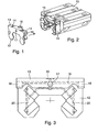
- FIGS. 1 and 2 there is a bearing element according to the invention the head piece each consisting of an end face arranged on the support body 10 Cage 11 and a closure plate 12. This is parallel to Longitudinal direction of the guide rail 4 in the direction of the arrow on the support body 10 brought up and placed on the cage 11.
- a closure strip 13 is integrally formed, with retaining cams 14 snap into recesses of retaining tabs 15 of the cage 11.
- the closure plate 12 with the sealing strip 13 has an upper relubrication hole 16, a front-side relubrication hole 17 and two side relubrication holes 18, of which only one is visible in FIG. 1.
- FIG. 3 shows schematically that in the closure plate 12 the Bores 16, 17 and 18 with a lubricant line 19 in the sealing strip 13 are connected, which in turn with lubricant lines 20 in the Closure plate 12 are connected. Via the lines 20 the Lubricant to the deflection areas and the rolling elements located there.
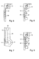
- FIG. 8 there are deflection shells 21 on the inside of the closure plate 12 attached, while such deflection shells in Figure 9 via elastic separating layers 22 are connected to the closure plate 12.
Landscapes
- Engineering & Computer Science (AREA)
- General Engineering & Computer Science (AREA)
- Mechanical Engineering (AREA)
- Bearings For Parts Moving Linearly (AREA)
- Rolling Contact Bearings (AREA)
Abstract
Description
- Figur 1
- eine Verschlussplatte für ein erfindungsgemäßes Lagerelement in perspektivischer Darstellung;
- Figur 2
- einen für die Aufnahme der Verschlußplatte nach Figur 1 angepaßten Tragkörper für ein erfindungsgemäßes Lagerelement in perspektivischer Darstellung;
- Figur 3
- eine schematische Darstellung der Innenseite der Verschlußplatte nach Figur 1;
- Figur 4
- ein an einer Führungsschiene längsverschieblich angeordnetes vorbekanntes Lagerelement in der Draufsicht;
- Figur 5
- einen Endbereich des Tragkörpers ohne Kopfstück des Lagerelementes nach Figur 4 in vergrößerter Darstellung;
- Figur 6
- die Verschlußplatte eines erfindungsgemäßen Lagerelementes in einer Seitenansicht;
- Figur 7
- die Verschlußplatte nach Figur 6 in der Draufsicht;
- Figur 8
- eine mit Umlenkschalen versehene Verschlußplatte eines erfindungsgemäßen Lagerelementes in einer Seitenansicht;
- Figur 9
- eine mit Umlenkschalen und elastischen Trennschichten versehene Verschlußplatte eines erfindungsgemäßen Lagerelementes in einer Seitenansicht;
- Figur 10
- eine weitere Verschlußplatte für ein erfindungsgemäßes Lagerelement in perspektivischer Darstellung;
- Figur 11
- einen weiteren für die Aufnahme der Verschlußplatte nach Figur 10 angepaßten Tragkörper für ein erfindungsgemäßes Lagerelement in perspektivischer Darstellung.
- 1
- Lagerelement
- 2
- Tragkörper
- 3
- Kopfstück
- 4
- Führungsschiene
- 5
- Lauffläche
- 6
- Schmiernippelträger
- 7
- Schraube
- 8
- Umlenksegment
- 9
- Führungsbord
- 10
- Tragkörper
- 11
- Käfig
- 12
- Verschlußplatte
- 13
- Verschlußleiste
- 14
- Haltenocken
- 15
- Haltelasche
- 16
- Obere Nachschmierbohrung
- 17
- Stirnseitige Nachschmierbohrung
- 18
- Seitliche Nachschmierbohrung
- 19
- Schmierstoffleitung der Leiste
- 20
- Schmierstoffleitung der Platte
- 21
- Umlenkschale
- 22
- Elastische Trennschicht
- 23
- Verschlußplatte
- 24
- Verschlußleiste
- 25
- Käfig
Claims (6)
- Linearwälzlagerelement für die Lagerung an der Lauffläche (5) einer Führungsschiene (4), mit einem Tragkörper (10), der für einen Wälzkörperumlauf jeweils eine zur Bewegungsrichtung des Tragkörpers (10) parallele Tragzone und einen Rücklaufkanal aufweist, die über zwei an dem Tragkörper (10) in stirnseitig angrenzenden Kopfstücken angeordnete Umlenkkanäle miteinander verbunden sind, wobei die Kopfstücke Schmierstoffleitungen (19, 20) enthalten und in der Tragzone, dem Rücklaufkanal und den Umlenkkanälen Führungsmittel in der Form einer Kunststoffbeschichtung für die Wälzkörper angeordnet sind, dadurch gekennzeichnet, dass jedes Kopfstück aus einem an dem Tragkörper (10) stirnseitig angeordneten Käfig (11, 25) und einer an dem Käfig (11, 25) angepaßten und angesetzten, die Schmierstoffleitungen (19, 20) enthaltenden, einstückigen Verschlußplatte (12, 23) gebildet ist.
- Lagerelement nach Anspruch 1, dadurch gekennzeichnet, dass an der Verschlußplatte (12, 23) eine mit einer Schmierstoffleitung (19) versehene Verschlußleiste (13, 24) angeformt ist.
- Lagerelement nach Anspruch 2, dadurch gekennzeichnet, dass in die Verschlußleiste (13, 24) Nachschmierbohrungen (16, 17, 18) eingebracht sind, über welche die Schmierstoffleitung (19) der Verschlußleiste (13, 24) und die Schmierstoffleitungen (20) der Verschlußplatte (12, 23) nach außen geöffnet sind.
- Lagerelement nach Anspruch 3, dadurch gekennzeichnet, dass die Verschlußleiste (13, 24) eine obere Nachschmierbohrung (16) und / oder zwei seitliche Nachschmierbohrungen (18) sowie eine stirnseitige Nachschmierbohrung (17) enthält.
- Lagerelement nach Anspruch 1, dadurch gekennzeichnet, dass für die Bildung der Umlenkkanäle an der Innenseite der Verschlußplatte (12, 23) Umlenkschalen (21) befestigt sind.
- Lagerelement nach Anspruch 5, dadurch gekennzeichnet, dass zwischen der Innenseite der Verschlußplatte (12, 23) und jeder Umlenkschale (21) eine elastische Trennschicht (22) angeordnet ist.
Applications Claiming Priority (2)
| Application Number | Priority Date | Filing Date | Title |
|---|---|---|---|
| DE10126439A DE10126439A1 (de) | 2001-05-31 | 2001-05-31 | Linearwälzlagerelement |
| DE10126439 | 2001-05-31 |
Publications (3)
| Publication Number | Publication Date |
|---|---|
| EP1262673A2 true EP1262673A2 (de) | 2002-12-04 |
| EP1262673A3 EP1262673A3 (de) | 2004-09-29 |
| EP1262673B1 EP1262673B1 (de) | 2011-10-05 |
Family
ID=7686704
Family Applications (1)
| Application Number | Title | Priority Date | Filing Date |
|---|---|---|---|
| EP02008783A Expired - Lifetime EP1262673B1 (de) | 2001-05-31 | 2002-04-19 | Linearwälzlagerelement |
Country Status (6)
| Country | Link |
|---|---|
| US (1) | US6715920B2 (de) |
| EP (1) | EP1262673B1 (de) |
| JP (1) | JP4375941B2 (de) |
| AT (1) | ATE527457T1 (de) |
| DE (1) | DE10126439A1 (de) |
| ES (1) | ES2372928T3 (de) |
Cited By (1)
| Publication number | Priority date | Publication date | Assignee | Title |
|---|---|---|---|---|
| DE102007056860A1 (de) * | 2007-11-26 | 2009-05-28 | Robert Bosch Gmbh | Linearwälzlager mit gemeinsamen Verschlusselementen für Wälzkörpereinfüllkanäle |
Families Citing this family (14)
| Publication number | Priority date | Publication date | Assignee | Title |
|---|---|---|---|---|
| JP3948973B2 (ja) * | 2002-02-07 | 2007-07-25 | Thk株式会社 | 潤滑剤塗布機能付ねじ装置 |
| US20050173195A1 (en) * | 2004-02-06 | 2005-08-11 | Lin Anita | Lubrication system of linear guideway |
| US20060204151A1 (en) * | 2005-03-08 | 2006-09-14 | Chin-Pei Wang | Lubrication device for linear slide guide |
| EP1736675B1 (de) * | 2005-06-23 | 2008-03-19 | Bosch Rexroth Mechatronics GmbH | Linearbewegungsvorrichtung mit RFID-Tag |
| US7736059B2 (en) * | 2006-12-27 | 2010-06-15 | Hiwin Technologies Corp. | Linear motion guide apparatus having changeable wiper |
| US7658544B2 (en) * | 2007-03-20 | 2010-02-09 | Hiwin Technologies Corp. | Linear motion guide apparatus having changeable wiper |
| DE102007013945A1 (de) * | 2007-03-23 | 2008-09-25 | Schaeffler Kg | Schmiervorrichtung für ein Linearwälzlager |
| TWM330884U (en) * | 2007-09-07 | 2008-04-21 | Ome Technology Co Ltd | Snap-on retention structure for linear rail |
| TWM356029U (en) * | 2008-12-05 | 2009-05-01 | Ome Technology Co Ltd | Pre-tightening structure for liner sliding rail |
| JP5668362B2 (ja) * | 2010-08-19 | 2015-02-12 | 日本精工株式会社 | リニアガイドのサイドシール |
| JP5756302B2 (ja) * | 2011-02-09 | 2015-07-29 | 日本トムソン株式会社 | 潤滑機能を備えた極小形の直動案内ユニット |
| TWM518739U (zh) * | 2015-12-30 | 2016-03-11 | 上銀科技股份有限公司 | 具有便拆式刮板的線性滑軌 |
| DE102021125612B3 (de) | 2021-10-04 | 2023-01-26 | Schaeffler Technologies AG & Co. KG | Führungswagen einer Linearführung |
| JP2025117105A (ja) * | 2024-01-30 | 2025-08-12 | 日本トムソン株式会社 | 直動案内ユニットおよびアダプタ |
Citations (1)
| Publication number | Priority date | Publication date | Assignee | Title |
|---|---|---|---|---|
| DE4331014C2 (de) | 1993-08-12 | 1997-09-04 | Schaeffler Waelzlager Kg | Linearwälzlagerelement |
Family Cites Families (13)
| Publication number | Priority date | Publication date | Assignee | Title |
|---|---|---|---|---|
| JP2544663Y2 (ja) * | 1991-03-29 | 1997-08-20 | 日本トムソン株式会社 | 直動転がり案内ユニットの側板 |
| DE4141038A1 (de) * | 1991-12-12 | 1993-06-17 | Schaeffler Waelzlager Kg | Abstreifereinheit fuer ein lagerelement |
| JPH0666319A (ja) * | 1992-06-19 | 1994-03-08 | Nippon Thompson Co Ltd | 転がり案内ユニット及びその製造方法 |
| JP2575895Y2 (ja) * | 1992-10-12 | 1998-07-02 | 日本トムソン株式会社 | 直動転がり案内ユニット |
| JP2563429Y2 (ja) * | 1992-11-12 | 1998-02-25 | 日本トムソン株式会社 | 直動転がり案内ユニットの潤滑装置 |
| JPH06173945A (ja) * | 1992-11-30 | 1994-06-21 | Nippon Seiko Kk | リニアガイド装置 |
| US5584581A (en) * | 1993-09-10 | 1996-12-17 | Deutsche Star Gmbh | Linear guiding device |
| DE19502498A1 (de) * | 1995-01-27 | 1996-08-01 | Schaeffler Waelzlager Kg | Linearwälzlager mit einer Schmiervorrichtung |
| JP3481771B2 (ja) * | 1996-04-25 | 2003-12-22 | Thk株式会社 | 直線案内装置のスライダの製造方法 |
| JP4070265B2 (ja) * | 1997-07-01 | 2008-04-02 | Thk株式会社 | 直線案内装置 |
| DE19830140A1 (de) * | 1998-07-06 | 2000-01-20 | Star Gmbh | Linearführungseinrichtung |
| DE19920477B4 (de) * | 1999-05-04 | 2007-06-21 | Chieftech Precision Co., Ltd. | Wälzführungseinrichtung für Linearbewegungen |
| JP2000346067A (ja) * | 1999-06-01 | 2000-12-12 | Thk Co Ltd | 直線運動装置 |
-
2001
- 2001-05-31 DE DE10126439A patent/DE10126439A1/de not_active Withdrawn
-
2002
- 2002-04-19 EP EP02008783A patent/EP1262673B1/de not_active Expired - Lifetime
- 2002-04-19 ES ES02008783T patent/ES2372928T3/es not_active Expired - Lifetime
- 2002-04-19 AT AT02008783T patent/ATE527457T1/de active
- 2002-05-28 JP JP2002153648A patent/JP4375941B2/ja not_active Expired - Fee Related
- 2002-05-30 US US10/161,506 patent/US6715920B2/en not_active Expired - Lifetime
Patent Citations (1)
| Publication number | Priority date | Publication date | Assignee | Title |
|---|---|---|---|---|
| DE4331014C2 (de) | 1993-08-12 | 1997-09-04 | Schaeffler Waelzlager Kg | Linearwälzlagerelement |
Cited By (2)
| Publication number | Priority date | Publication date | Assignee | Title |
|---|---|---|---|---|
| DE102007056860A1 (de) * | 2007-11-26 | 2009-05-28 | Robert Bosch Gmbh | Linearwälzlager mit gemeinsamen Verschlusselementen für Wälzkörpereinfüllkanäle |
| DE102007056860B4 (de) | 2007-11-26 | 2023-01-19 | Robert Bosch Gmbh | Linearwälzlager mit gemeinsamen Verschlusselementen für Wälzkörpereinfüllkanäle |
Also Published As
| Publication number | Publication date |
|---|---|
| US20020181810A1 (en) | 2002-12-05 |
| JP2003028159A (ja) | 2003-01-29 |
| ATE527457T1 (de) | 2011-10-15 |
| EP1262673A3 (de) | 2004-09-29 |
| US6715920B2 (en) | 2004-04-06 |
| JP4375941B2 (ja) | 2009-12-02 |
| ES2372928T3 (es) | 2012-01-27 |
| EP1262673B1 (de) | 2011-10-05 |
| DE10126439A1 (de) | 2002-12-05 |
Similar Documents
| Publication | Publication Date | Title |
|---|---|---|
| EP0211243B1 (de) | Wälzlager für Linearbewegungen | |
| DE4015699C2 (de) | ||
| EP1262673B1 (de) | Linearwälzlagerelement | |
| DE112006003560B4 (de) | Bewegungsführungsvorrichtung und Zusatzteil für Bewegungsführungsvorrichtung | |
| DE4331014C2 (de) | Linearwälzlagerelement | |
| DE112010002176T5 (de) | Bewegungs-Führungsvorrichtung und Spindelvorrichtung | |
| DE2601798C2 (de) | Lager | |
| DE19828587A1 (de) | Linearführungsvorrichtung | |
| EP1110005B1 (de) | Linearwälzlager | |
| DE19920477B4 (de) | Wälzführungseinrichtung für Linearbewegungen | |
| EP0399297A1 (de) | Zweireihiges Pendelrollenlager | |
| DE3730128C2 (de) | Kugelumlauflager für lineare Bewegungen | |
| DE69012741T2 (de) | Linearführung. | |
| DE3620571A1 (de) | Waelzlager fuer linearbewegungen | |
| DE3527886A1 (de) | Waelzlager fuer linearbewegungen | |
| DE7911040U1 (de) | Waelzlager fuer laengsbewegungen | |
| DE202016100552U1 (de) | Linearführung und Umlaufmodul sowie Gleitwagen dafür | |
| DE102020202872B4 (de) | Linearführungseinrichtung | |
| DE102017206583A1 (de) | Wälzkörpergewindetrieb mit Enddichtung im Hauptkörper und in der Endkappe | |
| DE112015001731T5 (de) | Rolleneinrichtung | |
| DE3342479C2 (de) | ||
| EP0919738A1 (de) | Schmiervorrichtung für ein Linearwälzlager | |
| DE4412797C2 (de) | Lagerelement mit einer Schmiervorrichtung | |
| EP1039158B1 (de) | Linearwälzlagerelement | |
| DE19741626B4 (de) | Kugellager für Längsbewegungen |
Legal Events
| Date | Code | Title | Description |
|---|---|---|---|
| PUAI | Public reference made under article 153(3) epc to a published international application that has entered the european phase |
Free format text: ORIGINAL CODE: 0009012 |
|
| 17P | Request for examination filed |
Effective date: 20020419 |
|
| AK | Designated contracting states |
Kind code of ref document: A2 Designated state(s): AT BE CH CY DE DK ES FI FR GB GR IE IT LI LU MC NL PT SE TR |
|
| AX | Request for extension of the european patent |
Free format text: AL;LT;LV;MK;RO;SI |
|
| PUAL | Search report despatched |
Free format text: ORIGINAL CODE: 0009013 |
|
| AK | Designated contracting states |
Kind code of ref document: A3 Designated state(s): AT BE CH CY DE DK ES FI FR GB GR IE IT LI LU MC NL PT SE TR |
|
| AX | Request for extension of the european patent |
Extension state: AL LT LV MK RO SI |
|
| RIC1 | Information provided on ipc code assigned before grant |
Ipc: 7F 16C 29/06 A Ipc: 7F 16C 33/66 B |
|
| AKX | Designation fees paid |
Designated state(s): AT BE CH CY DE DK ES FI FR GB GR IE IT LI LU MC NL PT SE TR |
|
| RAP1 | Party data changed (applicant data changed or rights of an application transferred) |
Owner name: SCHAEFFLER KG |
|
| 17Q | First examination report despatched |
Effective date: 20070926 |
|
| 111Z | Information provided on other rights and legal means of execution |
Free format text: AT BE CH CY DE DK ES FI FR GB GR IE IT LU MC NL PT SE TR Effective date: 20091216 |
|
| RAP1 | Party data changed (applicant data changed or rights of an application transferred) |
Owner name: SCHAEFFLER TECHNOLOGIES GMBH & CO. KG |
|
| GRAP | Despatch of communication of intention to grant a patent |
Free format text: ORIGINAL CODE: EPIDOSNIGR1 |
|
| GRAS | Grant fee paid |
Free format text: ORIGINAL CODE: EPIDOSNIGR3 |
|
| GRAA | (expected) grant |
Free format text: ORIGINAL CODE: 0009210 |
|
| AK | Designated contracting states |
Kind code of ref document: B1 Designated state(s): AT BE CH CY DE DK ES FI FR GB GR IE IT LI LU MC NL PT SE TR |
|
| REG | Reference to a national code |
Ref country code: GB Ref legal event code: FG4D Free format text: NOT ENGLISH |
|
| REG | Reference to a national code |
Ref country code: CH Ref legal event code: EP |
|
| REG | Reference to a national code |
Ref country code: IE Ref legal event code: FG4D |
|
| REG | Reference to a national code |
Ref country code: SE Ref legal event code: TRGR |
|
| REG | Reference to a national code |
Ref country code: DE Ref legal event code: R096 Ref document number: 50215227 Country of ref document: DE Effective date: 20111229 |
|
| REG | Reference to a national code |
Ref country code: NL Ref legal event code: VDEP Effective date: 20111005 |
|
| REG | Reference to a national code |
Ref country code: ES Ref legal event code: FG2A Ref document number: 2372928 Country of ref document: ES Kind code of ref document: T3 Effective date: 20120127 |
|
| RAP2 | Party data changed (patent owner data changed or rights of a patent transferred) |
Owner name: SCHAEFFLER TECHNOLOGIES AG & CO. KG |
|
| REG | Reference to a national code |
Ref country code: CH Ref legal event code: PFA Owner name: SCHAEFFLER TECHNOLOGIES AG & CO. KG Free format text: SCHAEFFLER TECHNOLOGIES GMBH & CO. KG#INDUSTRIESTRASSE 1-3#91074 HERZOGENAURACH (DE) -TRANSFER TO- SCHAEFFLER TECHNOLOGIES AG & CO. KG#INDUSTRIESTRASSE 1-3#91074 HERZOGENAURACH (DE) |
|
| REG | Reference to a national code |
Ref country code: IE Ref legal event code: FD4D |
|
| PG25 | Lapsed in a contracting state [announced via postgrant information from national office to epo] |
Ref country code: NL Free format text: LAPSE BECAUSE OF FAILURE TO SUBMIT A TRANSLATION OF THE DESCRIPTION OR TO PAY THE FEE WITHIN THE PRESCRIBED TIME-LIMIT Effective date: 20111005 Ref country code: PT Free format text: LAPSE BECAUSE OF FAILURE TO SUBMIT A TRANSLATION OF THE DESCRIPTION OR TO PAY THE FEE WITHIN THE PRESCRIBED TIME-LIMIT Effective date: 20120206 Ref country code: GR Free format text: LAPSE BECAUSE OF FAILURE TO SUBMIT A TRANSLATION OF THE DESCRIPTION OR TO PAY THE FEE WITHIN THE PRESCRIBED TIME-LIMIT Effective date: 20120106 |
|
| PG25 | Lapsed in a contracting state [announced via postgrant information from national office to epo] |
Ref country code: CY Free format text: LAPSE BECAUSE OF FAILURE TO SUBMIT A TRANSLATION OF THE DESCRIPTION OR TO PAY THE FEE WITHIN THE PRESCRIBED TIME-LIMIT Effective date: 20111005 |
|
| PG25 | Lapsed in a contracting state [announced via postgrant information from national office to epo] |
Ref country code: DK Free format text: LAPSE BECAUSE OF FAILURE TO SUBMIT A TRANSLATION OF THE DESCRIPTION OR TO PAY THE FEE WITHIN THE PRESCRIBED TIME-LIMIT Effective date: 20111005 Ref country code: IE Free format text: LAPSE BECAUSE OF FAILURE TO SUBMIT A TRANSLATION OF THE DESCRIPTION OR TO PAY THE FEE WITHIN THE PRESCRIBED TIME-LIMIT Effective date: 20111005 |
|
| PLBE | No opposition filed within time limit |
Free format text: ORIGINAL CODE: 0009261 |
|
| STAA | Information on the status of an ep patent application or granted ep patent |
Free format text: STATUS: NO OPPOSITION FILED WITHIN TIME LIMIT |
|
| 26N | No opposition filed |
Effective date: 20120706 |
|
| REG | Reference to a national code |
Ref country code: DE Ref legal event code: R081 Ref document number: 50215227 Country of ref document: DE Owner name: SCHAEFFLER TECHNOLOGIES AG & CO. KG, DE Free format text: FORMER OWNER: SCHAEFFLER TECHNOLOGIES GMBH & CO. KG, 91074 HERZOGENAURACH, DE Effective date: 20120828 Ref country code: DE Ref legal event code: R081 Ref document number: 50215227 Country of ref document: DE Owner name: SCHAEFFLER TECHNOLOGIES GMBH & CO. KG, DE Free format text: FORMER OWNER: INA-SCHAEFFLER KG, 91074 HERZOGENAURACH, DE Effective date: 20111109 Ref country code: DE Ref legal event code: R081 Ref document number: 50215227 Country of ref document: DE Owner name: SCHAEFFLER TECHNOLOGIES GMBH & CO. KG, DE Free format text: FORMER OWNER: SCHAEFFLER TECHNOLOGIES GMBH & CO. KG, 91074 HERZOGENAURACH, DE Effective date: 20120828 Ref country code: DE Ref legal event code: R081 Ref document number: 50215227 Country of ref document: DE Owner name: SCHAEFFLER TECHNOLOGIES AG & CO. KG, DE Free format text: FORMER OWNER: INA-SCHAEFFLER KG, 91074 HERZOGENAURACH, DE Effective date: 20111109 |
|
| BERE | Be: lapsed |
Owner name: SCHAEFFLER TECHNOLOGIES G.M.B.H. & CO. KG Effective date: 20120430 |
|
| REG | Reference to a national code |
Ref country code: DE Ref legal event code: R097 Ref document number: 50215227 Country of ref document: DE Effective date: 20120706 |
|
| PG25 | Lapsed in a contracting state [announced via postgrant information from national office to epo] |
Ref country code: MC Free format text: LAPSE BECAUSE OF NON-PAYMENT OF DUE FEES Effective date: 20120430 |
|
| REG | Reference to a national code |
Ref country code: FR Ref legal event code: ST Effective date: 20121228 |
|
| PG25 | Lapsed in a contracting state [announced via postgrant information from national office to epo] |
Ref country code: BE Free format text: LAPSE BECAUSE OF NON-PAYMENT OF DUE FEES Effective date: 20120430 |
|
| PG25 | Lapsed in a contracting state [announced via postgrant information from national office to epo] |
Ref country code: FR Free format text: LAPSE BECAUSE OF NON-PAYMENT OF DUE FEES Effective date: 20120430 |
|
| REG | Reference to a national code |
Ref country code: AT Ref legal event code: MM01 Ref document number: 527457 Country of ref document: AT Kind code of ref document: T Effective date: 20120419 |
|
| PG25 | Lapsed in a contracting state [announced via postgrant information from national office to epo] |
Ref country code: FI Free format text: LAPSE BECAUSE OF FAILURE TO SUBMIT A TRANSLATION OF THE DESCRIPTION OR TO PAY THE FEE WITHIN THE PRESCRIBED TIME-LIMIT Effective date: 20111005 |
|
| PG25 | Lapsed in a contracting state [announced via postgrant information from national office to epo] |
Ref country code: AT Free format text: LAPSE BECAUSE OF NON-PAYMENT OF DUE FEES Effective date: 20120419 |
|
| REG | Reference to a national code |
Ref country code: DE Ref legal event code: R081 Ref document number: 50215227 Country of ref document: DE Owner name: SCHAEFFLER TECHNOLOGIES GMBH & CO. KG, DE Free format text: FORMER OWNER: SCHAEFFLER TECHNOLOGIES AG & CO. KG, 91074 HERZOGENAURACH, DE Effective date: 20140218 Ref country code: DE Ref legal event code: R081 Ref document number: 50215227 Country of ref document: DE Owner name: SCHAEFFLER TECHNOLOGIES AG & CO. KG, DE Free format text: FORMER OWNER: SCHAEFFLER TECHNOLOGIES AG & CO. KG, 91074 HERZOGENAURACH, DE Effective date: 20140218 |
|
| PG25 | Lapsed in a contracting state [announced via postgrant information from national office to epo] |
Ref country code: TR Free format text: LAPSE BECAUSE OF FAILURE TO SUBMIT A TRANSLATION OF THE DESCRIPTION OR TO PAY THE FEE WITHIN THE PRESCRIBED TIME-LIMIT Effective date: 20111005 |
|
| PG25 | Lapsed in a contracting state [announced via postgrant information from national office to epo] |
Ref country code: LU Free format text: LAPSE BECAUSE OF NON-PAYMENT OF DUE FEES Effective date: 20120419 |
|
| REG | Reference to a national code |
Ref country code: CH Ref legal event code: PFUS Owner name: SCHAEFFLER TECHNOLOGIES GMBH AND CO. KG, DE Free format text: FORMER OWNER: SCHAEFFLER TECHNOLOGIES AG AND CO. KG, DE |
|
| REG | Reference to a national code |
Ref country code: DE Ref legal event code: R081 Ref document number: 50215227 Country of ref document: DE Owner name: SCHAEFFLER TECHNOLOGIES AG & CO. KG, DE Free format text: FORMER OWNER: SCHAEFFLER TECHNOLOGIES GMBH & CO. KG, 91074 HERZOGENAURACH, DE Effective date: 20150211 |
|
| REG | Reference to a national code |
Ref country code: CH Ref legal event code: PFA Owner name: SCHAEFFLER TECHNOLOGIES AG AND CO. KG, DE Free format text: FORMER OWNER: SCHAEFFLER TECHNOLOGIES GMBH AND CO. KG, DE |
|
| REG | Reference to a national code |
Ref country code: ES Ref legal event code: PC2A Owner name: SCHAEFFLER TECHNOLOGIES AG & CO.KG Effective date: 20150512 |
|
| PGFP | Annual fee paid to national office [announced via postgrant information from national office to epo] |
Ref country code: DE Payment date: 20170630 Year of fee payment: 16 |
|
| PGFP | Annual fee paid to national office [announced via postgrant information from national office to epo] |
Ref country code: ES Payment date: 20180522 Year of fee payment: 17 Ref country code: CH Payment date: 20180426 Year of fee payment: 17 |
|
| PGFP | Annual fee paid to national office [announced via postgrant information from national office to epo] |
Ref country code: IT Payment date: 20180424 Year of fee payment: 17 |
|
| PGFP | Annual fee paid to national office [announced via postgrant information from national office to epo] |
Ref country code: SE Payment date: 20180427 Year of fee payment: 17 |
|
| PGFP | Annual fee paid to national office [announced via postgrant information from national office to epo] |
Ref country code: GB Payment date: 20180427 Year of fee payment: 17 |
|
| REG | Reference to a national code |
Ref country code: DE Ref legal event code: R119 Ref document number: 50215227 Country of ref document: DE |
|
| PG25 | Lapsed in a contracting state [announced via postgrant information from national office to epo] |
Ref country code: DE Free format text: LAPSE BECAUSE OF NON-PAYMENT OF DUE FEES Effective date: 20181101 |
|
| REG | Reference to a national code |
Ref country code: CH Ref legal event code: PL |
|
| REG | Reference to a national code |
Ref country code: SE Ref legal event code: EUG |
|
| GBPC | Gb: european patent ceased through non-payment of renewal fee |
Effective date: 20190419 |
|
| PG25 | Lapsed in a contracting state [announced via postgrant information from national office to epo] |
Ref country code: CH Free format text: LAPSE BECAUSE OF NON-PAYMENT OF DUE FEES Effective date: 20190430 Ref country code: SE Free format text: LAPSE BECAUSE OF NON-PAYMENT OF DUE FEES Effective date: 20190420 Ref country code: LI Free format text: LAPSE BECAUSE OF NON-PAYMENT OF DUE FEES Effective date: 20190430 Ref country code: GB Free format text: LAPSE BECAUSE OF NON-PAYMENT OF DUE FEES Effective date: 20190419 |
|
| PG25 | Lapsed in a contracting state [announced via postgrant information from national office to epo] |
Ref country code: IT Free format text: LAPSE BECAUSE OF NON-PAYMENT OF DUE FEES Effective date: 20190419 |
|
| REG | Reference to a national code |
Ref country code: ES Ref legal event code: FD2A Effective date: 20200831 |
|
| PG25 | Lapsed in a contracting state [announced via postgrant information from national office to epo] |
Ref country code: ES Free format text: LAPSE BECAUSE OF NON-PAYMENT OF DUE FEES Effective date: 20190420 |
|
| P01 | Opt-out of the competence of the unified patent court (upc) registered |
Effective date: 20230522 |