EP1262655A2 - Brennstoffeinspritzventil - Google Patents
Brennstoffeinspritzventil Download PDFInfo
- Publication number
- EP1262655A2 EP1262655A2 EP02011017A EP02011017A EP1262655A2 EP 1262655 A2 EP1262655 A2 EP 1262655A2 EP 02011017 A EP02011017 A EP 02011017A EP 02011017 A EP02011017 A EP 02011017A EP 1262655 A2 EP1262655 A2 EP 1262655A2
- Authority
- EP
- European Patent Office
- Prior art keywords
- stop surface
- fuel injection
- injection valve
- anchor
- damping element
- Prior art date
- Legal status (The legal status is an assumption and is not a legal conclusion. Google has not performed a legal analysis and makes no representation as to the accuracy of the status listed.)
- Granted
Links
- 239000000446 fuel Substances 0.000 title claims abstract description 51
- 238000002347 injection Methods 0.000 title claims abstract description 22
- 239000007924 injection Substances 0.000 title claims abstract description 22
- 238000013016 damping Methods 0.000 claims abstract description 16
- 238000002485 combustion reaction Methods 0.000 claims abstract description 8
- 238000007789 sealing Methods 0.000 claims abstract description 5
- 229920001971 elastomer Polymers 0.000 claims description 4
- 239000000806 elastomer Substances 0.000 claims description 4
- 239000007921 spray Substances 0.000 description 4
- 238000011161 development Methods 0.000 description 3
- 230000018109 developmental process Effects 0.000 description 3
- 230000002349 favourable effect Effects 0.000 description 3
- 230000005291 magnetic effect Effects 0.000 description 3
- 238000004519 manufacturing process Methods 0.000 description 2
- 230000005540 biological transmission Effects 0.000 description 1
- 230000015572 biosynthetic process Effects 0.000 description 1
- 230000015556 catabolic process Effects 0.000 description 1
- 238000006731 degradation reaction Methods 0.000 description 1
- 230000000994 depressogenic effect Effects 0.000 description 1
- 239000013536 elastomeric material Substances 0.000 description 1
- 230000005284 excitation Effects 0.000 description 1
- 230000005294 ferromagnetic effect Effects 0.000 description 1
- 230000000284 resting effect Effects 0.000 description 1
Images
Classifications
-
- F—MECHANICAL ENGINEERING; LIGHTING; HEATING; WEAPONS; BLASTING
- F02—COMBUSTION ENGINES; HOT-GAS OR COMBUSTION-PRODUCT ENGINE PLANTS
- F02M—SUPPLYING COMBUSTION ENGINES IN GENERAL WITH COMBUSTIBLE MIXTURES OR CONSTITUENTS THEREOF
- F02M51/00—Fuel-injection apparatus characterised by being operated electrically
- F02M51/06—Injectors peculiar thereto with means directly operating the valve needle
- F02M51/061—Injectors peculiar thereto with means directly operating the valve needle using electromagnetic operating means
- F02M51/0625—Injectors peculiar thereto with means directly operating the valve needle using electromagnetic operating means characterised by arrangement of mobile armatures
- F02M51/0664—Injectors peculiar thereto with means directly operating the valve needle using electromagnetic operating means characterised by arrangement of mobile armatures having a cylindrically or partly cylindrically shaped armature, e.g. entering the winding; having a plate-shaped or undulated armature entering the winding
- F02M51/0671—Injectors peculiar thereto with means directly operating the valve needle using electromagnetic operating means characterised by arrangement of mobile armatures having a cylindrically or partly cylindrically shaped armature, e.g. entering the winding; having a plate-shaped or undulated armature entering the winding the armature having an elongated valve body attached thereto
-
- F—MECHANICAL ENGINEERING; LIGHTING; HEATING; WEAPONS; BLASTING
- F02—COMBUSTION ENGINES; HOT-GAS OR COMBUSTION-PRODUCT ENGINE PLANTS
- F02M—SUPPLYING COMBUSTION ENGINES IN GENERAL WITH COMBUSTIBLE MIXTURES OR CONSTITUENTS THEREOF
- F02M2200/00—Details of fuel-injection apparatus, not otherwise provided for
- F02M2200/09—Fuel-injection apparatus having means for reducing noise
-
- F—MECHANICAL ENGINEERING; LIGHTING; HEATING; WEAPONS; BLASTING
- F02—COMBUSTION ENGINES; HOT-GAS OR COMBUSTION-PRODUCT ENGINE PLANTS
- F02M—SUPPLYING COMBUSTION ENGINES IN GENERAL WITH COMBUSTIBLE MIXTURES OR CONSTITUENTS THEREOF
- F02M2200/00—Details of fuel-injection apparatus, not otherwise provided for
- F02M2200/30—Fuel-injection apparatus having mechanical parts, the movement of which is damped
- F02M2200/306—Fuel-injection apparatus having mechanical parts, the movement of which is damped using mechanical means
-
- F—MECHANICAL ENGINEERING; LIGHTING; HEATING; WEAPONS; BLASTING
- F02—COMBUSTION ENGINES; HOT-GAS OR COMBUSTION-PRODUCT ENGINE PLANTS
- F02M—SUPPLYING COMBUSTION ENGINES IN GENERAL WITH COMBUSTIBLE MIXTURES OR CONSTITUENTS THEREOF
- F02M2200/00—Details of fuel-injection apparatus, not otherwise provided for
- F02M2200/90—Selection of particular materials
- F02M2200/9015—Elastomeric or plastic materials
Definitions
- the invention is based on a fuel injector according to the genus of the main claim.
- DE 198 16 315 describes a fuel injection valve for Known fuel injection systems of internal combustion engines, especially for direct injection of fuel into a combustion chamber of the internal combustion engine, the one by a Solenoid in one stroke direction against a first one Return spring loaded armature and one with a Valve closing body related valve needle having.
- the valve needle has a first stop for the anchor moving on it, the anchor additionally acted on by a second return spring is. Furthermore, a stationary second stop for the Anchor provided.
- the second return spring acts on the Anchor against the stroke direction and stops in one Rest position when the solenoid coil is not energized second stop in such a way that the anchor from the Valve needle trained first stop around a predetermined distance is spaced.
- This known version of a fuel injector also with one acting on the anchor second return spring does not prevent one Noise when hitting the anchor on one Stroke limit stop.
- the known version serves only for debouncing the placement of the valve needle on the Valve closing body.
- the fuel injector according to the invention with the has characteristic features of the main claim in contrast the advantage that when the valve needle is lifted, before the anchor with its anchor stop surface Counter stop surface reached, the elastic Damping element is compressed and by this Delay no pulse spike occurs and the Noise is minimized.
- the invention Fuel injector is also inexpensive and simple to manufacture, since only one recess in one of the Stop surfaces must be provided.
- the damping element is preferably in the Counter stop surface arranged.
- the elastic damping element can then by jamming be fixed, since this surface is not on a moving component is formed.
- the recess is a circular, concentrically arranged to the valve needle Groove that has a radius that is approximately the center between the smallest circumferential radius and the largest circumferential radius corresponds to the counter stop surface.
- the recess can advantageously be manufactured inexpensively, since the groove is concentric to an axis of symmetry of the armature lies in which the valve needle is arranged.
- the anchor is turned around this part during its manufacture Symmetry axis rotatably clamped and an additional groove can be attached with little effort.
- the choice of Radius of the circular groove approximately in the middle of the free area the counter stop surface with respect to a radial cut results in a favorable introduction of force when hitting the Damping element and the lowest possible vibrations and thus Sound DEVELOPMENT.
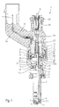
- FIG Execution of a fuel injector 1 in one Overview presentation can be described.
- FIG. 1 shows fuel injector 1 apart from the measures according to the invention with regard to its essential components of known fuel injection valve 1 represents.
- the fuel injector 1 is in the form of a Fuel injector 1 for fuel injection systems of mixture-compressing, spark-ignited Running internal combustion engines. It is particularly suitable for injecting fuel directly into one Shown combustion chamber of an internal combustion engine.
- the fuel injector 1 consists of a Nozzle body 2, in which a valve needle 3 is arranged.
- the valve needle 3 stands with a valve closing body 4 in Active connection with one on a valve seat body 5 arranged valve seat surface 6 to a sealing seat interacts.
- the fuel injector 1 is acting it is an inward opening in the exemplary embodiment Fuel injector 1, which has a Spray opening 7 has.
- the nozzle body 2 is through a Seal 8 against an outer pole 9 of a magnet coil 10 sealed.
- the magnet coil 10 is in a coil housing 11 encapsulated and wound on a bobbin 12, which bears against an inner pole 13 of the magnet coil 10.
- the Inner pole 13 and outer pole 9 are through a constriction 26 separated from each other and not by one another ferromagnetic connecting member 29 connected.
- the Solenoid 10 is connected via a line 19 from one to the other an electrical plug contact 17 feedable electrical Current excited.
- the plug contact 17 is one Surround plastic sheath 18 on the inner pole 13th can be
- the valve needle 3 is in a valve needle guide 14 led, which is disc-shaped. to A paired adjusting disc 15 is used for stroke adjustment the other side of the shim 15 is the Anchor 20. This stands over a first flange 21 non-positively in connection with the valve needle 3, which by a weld seam 22 with the first flange 21 connected is. One is supported on the first flange 21 Return spring 23, which in the present design of the Fuel injector 1 through a sleeve 24 Bias is brought.
- Fuel channels 30a to 30c The fuel is about one central fuel supply 16 supplied and by a Filter element 25 filtered.
- the fuel injector 1 is no further by a seal 28 against one fuel line shown sealed.
- a annular damping element 32 On the spray side of the armature 20 is a annular damping element 32, which consists of a Elastomeric material is arranged. It's on one second flange 31, which has a weld seam 33 is non-positively connected to the valve needle 3.
- the armature 20 has on its side facing away from the spray side Side an anchor stop surface 34 which with a Counter stop surface 35 cooperates and the stroke of Valve needle 3 limited.
- an anchor stop surface 34 which with a Counter stop surface 35 cooperates and the stroke of Valve needle 3 limited.
- the Counter stop surface 35 is an O-ring 37 as Damping element used.
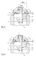
- Fig. 2 shows an enlarged sectional view of an enlarged view of area II in Fig. 1. Shown is a part of the valve needle 3, the first flange 21 welded to it by the weld 22 and the armature 20 with the fuel channel 30a running therein and the Armature stop surface 34. Armature stop surface 34 cooperates with counter-stop surface 35 in order to limit the stroke of valve needle 3 and armature 20. Due to the second flange 31 connected to the weld 33 with the valve needle 3, the armature 20 is held between the first flange 21 and the second flange 31 via the damping element 32. According to the invention, the exemplary embodiment shown in FIG.
- annular groove 36 in the counter abutment surface 35, the radius r of which corresponds approximately to the center between the smallest circumferential radius r min and the largest circumferential radius r max of the counter abutment surface 35.
- annular groove 36 In the annular groove 36, an O-ring 37 is inserted, which protrudes u over the counter abutment surface 35.
- the armature 20 comes with its anchor stop surface 34 at a distance u before Stop the anchor stop surface 34 on the Counter abutment surface 35 in contact with the O-ring 37. Under Deformation of the O-ring 37, the armature 20 is braked until the anchor stop surface 34 and the counter stop surface 35 lie together. There is no impulse peak and that associated noise when opening the Surfaces on each other.
- the radius r is one possible free-floating length on the surface of the Anchor stop surface 34 and the counter stop surface 35 minimized. This also makes the sound development favorable affected.
- FIG. 3 shows an excerpted sectional view Another embodiment of the invention Fuel injector 1 corresponding to area II of the Fig. 1.
- the structure corresponds to that in Fig. 2nd shown with the valve needle 3, which by the Weld 22 on this welded first flange 21, the armature 20, the fuel channel 30a running therein, the anchor stop surface 34 and the counter stop surface 35.
- the valve needle 3 Through the weld 33 with the valve needle 3 connected second flange 31 is over the Damping element 32 of armature 20 between first flange 21 and second flange 31 held.
- the illustrated embodiment is in the annular groove 36 in a square ring 38 is inserted into the counter stop surface 35, by a projection u over the counter stop surface 35 survives.
- the embodiment described can be a stronger one braking force can be achieved.
- the invention is not shown on the Embodiments limited and z. B. also for after externally opening fuel injection valves 1 or others Anchor shapes are suitable, provided they have a flat stop exhibit.
Landscapes
- Engineering & Computer Science (AREA)
- Physics & Mathematics (AREA)
- Electromagnetism (AREA)
- Chemical & Material Sciences (AREA)
- Combustion & Propulsion (AREA)
- Mechanical Engineering (AREA)
- General Engineering & Computer Science (AREA)
- Fuel-Injection Apparatus (AREA)
Abstract
Description
- Fig. 1
- einen schematischen Schnitt durch ein erfindungsgemäßes Ausführungsbeispiel eines Brennstoffeinspritzventils,
- Fig. 2
- einen Detailausschnitt eines erfindungsgemäßen Brennstoffeinspritzventils entsprechend dem Bereich II in der Fig. 1 und
- Fig. 3
- einen Detailausschnitt eines weiteren erfindungsgemäßen Brennstoffeinspritzventils entsprechend dem Bereich II in der Fig. 1.
Claims (9)
- Brennstoffeinspritzventil (1), insbesondere Einspritzventil für Brennstoffeinspritzanlagen von Brennkraftmaschinen, mit einer Ventilnadel (3), die mit einer Ventilsitzfläche (6) zu einem Dichtsitz zusammenwirkt, und mit einem an der Ventilnadel (3) angreifenden Anker (20), der eine dem Ventilsitz abgewandte Ankeranschlagfläche (34) als eine erste Anschlagfläche aufweist, und wobei eine Gegenanschlagfläche (35) als eine zweite Anschlagfläche dient, die mit der Ankeranschlagfläche (34) zusammenwirkt,
dadurch gekennzeichnet, daß die Ankeranschlagfläche (34) und/oder die Gegenanschlagfläche (35) in einer Ausnehmung (36) ein elastisches Dämpfungselement (37,38) aufweist, das über die Ankeranschlagfläche (34) bzw. die Gegenanschlagfläche (35) übersteht. - Brennstoffeinspritzventil nach Anspruch 1,
dadurch gekennzeichnet, daß das Dämpfungselement (37, 38) in der Gegenanschlagfläche (35) angeordnet ist. - Brennstoffeinspritzventil nach Anspruch 1 oder 2,
dadurch gekennzeichnet, daß die Ausnehmung eine kreisförmige Nut (36) ist. - Brennstoffeinspritzventil nach Anspruch 3,
dadurch gekennzeichnet, daß die kreisfömige Nut (36) konzentrisch zur Ventilnadel (3) angeordnet ist. - Brennstoffeinspritzventil nach Anspruch 4,
dadurch gekennzeichnet, daß die kreisförmige Nut (36) einen Radius (r) aufweist, der ungefähr der Mitte zwischen kleinstem Umfangsradius (rmin) und größtem Umfangsradius (rmax) der Gegenanschlagfläche (35) entspricht. - Brennstoffeinspritzventil nach Anspruch 4 oder 5,
dadurch gekennzeichnet, daß das Dämpfungselement ein Vierkantring (38) aus einem Elastomer ist. - Brennstoffeinspritzventil nach Anspruch 4 oder 5,
dadurch gekennzeichnet, daß das Dämpfungselement ein O-Ring (37) aus einem Elastomer ist. - Brennstoffeinspritzventil nach Anspruch 6 oder 7,
dadurch gekennzeichnet, daß das Elastizitätsmodul des Dämpfungselements (37, 38) so gewählt ist, daß bei angezogenem Anker (20) das Dämpfungselement (37, 38) in die Nut (36) gedrückt wird und die Ankeranschlagfläche (34) und die Gegenanschlagfläche (35) aneinander anliegen. - Brennstoffeinspritzventil nach Anspruch 1 oder 2,
dadurch gekennzeichnet, daß das elastische Dämpfungselement (37, 38) ein Federelement ist.
Applications Claiming Priority (2)
| Application Number | Priority Date | Filing Date | Title |
|---|---|---|---|
| DE10124747A DE10124747A1 (de) | 2001-05-21 | 2001-05-21 | Brennstoffeinspritzventil |
| DE10124747 | 2001-05-21 |
Publications (3)
| Publication Number | Publication Date |
|---|---|
| EP1262655A2 true EP1262655A2 (de) | 2002-12-04 |
| EP1262655A3 EP1262655A3 (de) | 2004-01-21 |
| EP1262655B1 EP1262655B1 (de) | 2005-03-30 |
Family
ID=7685601
Family Applications (1)
| Application Number | Title | Priority Date | Filing Date |
|---|---|---|---|
| EP02011017A Expired - Lifetime EP1262655B1 (de) | 2001-05-21 | 2002-05-17 | Brennstoffeinspritzventil |
Country Status (3)
| Country | Link |
|---|---|
| EP (1) | EP1262655B1 (de) |
| JP (1) | JP4327409B2 (de) |
| DE (2) | DE10124747A1 (de) |
Cited By (5)
| Publication number | Priority date | Publication date | Assignee | Title |
|---|---|---|---|---|
| US7721713B2 (en) | 2006-02-17 | 2010-05-25 | Hitachi, Ltd. | Electromagnetic fuel injector and method for assembling the same |
| WO2012084328A1 (de) * | 2010-12-23 | 2012-06-28 | Robert Bosch Gmbh | Ventil zum einspritzen von kraftstoff |
| EP2860386A1 (de) * | 2013-10-10 | 2015-04-15 | Continental Automotive GmbH | Injektor für eine Brennkraftmaschine |
| EP3346122A1 (de) * | 2017-01-10 | 2018-07-11 | Continental Automotive GmbH | Elektromagnetisches schaltventil und kraftstoffhochdruckpumpe |
| CN109654283A (zh) * | 2017-10-12 | 2019-04-19 | 罗伯特·博世有限公司 | 用于配量流体的阀、尤其气体阀 |
Families Citing this family (7)
| Publication number | Priority date | Publication date | Assignee | Title |
|---|---|---|---|---|
| DE10308914B4 (de) * | 2003-02-28 | 2013-11-14 | Robert Bosch Gmbh | Brennstoffeinspritzventil |
| JP4576345B2 (ja) | 2006-02-17 | 2010-11-04 | 日立オートモティブシステムズ株式会社 | 電磁式燃料噴射弁 |
| DE102006021736A1 (de) * | 2006-05-10 | 2007-11-15 | Robert Bosch Gmbh | Kraftstoffinjektor mit druckausgeglichenem Steuerventil |
| DE102015201005A1 (de) * | 2015-01-22 | 2016-07-28 | Robert Bosch Gmbh | Brennstoffeinspritzventil |
| DE102015226181A1 (de) * | 2015-12-21 | 2017-06-22 | Robert Bosch Gmbh | Ventil zum Zumessen eines Fluids |
| JP2018009548A (ja) * | 2016-07-15 | 2018-01-18 | 株式会社デンソー | 燃料噴射弁 |
| DE102018200848B4 (de) * | 2018-01-19 | 2025-05-08 | Schaeffler Technologies AG & Co. KG | Elektromagnetisches Schaltventil |
Citations (2)
| Publication number | Priority date | Publication date | Assignee | Title |
|---|---|---|---|---|
| US4766405A (en) | 1987-04-14 | 1988-08-23 | Allied Corporation | Dynamic energy absorber |
| DE19816315A1 (de) | 1998-04-11 | 1999-10-14 | Bosch Gmbh Robert | Brennstoffeinspritzventil |
Family Cites Families (7)
| Publication number | Priority date | Publication date | Assignee | Title |
|---|---|---|---|---|
| DE3314899A1 (de) * | 1983-04-25 | 1984-10-25 | Mesenich, Gerhard, Dipl.-Ing., 4630 Bochum | Federanordnung mit zusatzmasse zur verbesserung des dynamischen verhaltens von elektromagnetsystemen |
| DE19849210A1 (de) * | 1998-10-26 | 2000-04-27 | Bosch Gmbh Robert | Brennstoffeinspritzventil |
| EP1054152A3 (de) * | 1999-05-19 | 2002-08-14 | HydraForce, Inc. | Elektrisch gesteuertes Ventil mit Vorrichtung zur Steuerung einer nichtlinearen Kraft |
| DE19927900A1 (de) * | 1999-06-18 | 2000-12-21 | Bosch Gmbh Robert | Brennstoffeinspritzventil |
| DE19935263A1 (de) * | 1999-07-27 | 2001-02-01 | Bosch Gmbh Robert | Brennstoffeinspritzventil |
| DE19948238A1 (de) * | 1999-10-07 | 2001-04-19 | Bosch Gmbh Robert | Brennstoffeinspritzventil |
| DE10017030B4 (de) * | 2000-03-31 | 2005-05-19 | Rausch & Pausch Gmbh | Magnetventil |
-
2001
- 2001-05-21 DE DE10124747A patent/DE10124747A1/de not_active Withdrawn
-
2002
- 2002-05-17 EP EP02011017A patent/EP1262655B1/de not_active Expired - Lifetime
- 2002-05-17 DE DE50202602T patent/DE50202602D1/de not_active Expired - Lifetime
- 2002-05-21 JP JP2002146592A patent/JP4327409B2/ja not_active Expired - Fee Related
Patent Citations (2)
| Publication number | Priority date | Publication date | Assignee | Title |
|---|---|---|---|---|
| US4766405A (en) | 1987-04-14 | 1988-08-23 | Allied Corporation | Dynamic energy absorber |
| DE19816315A1 (de) | 1998-04-11 | 1999-10-14 | Bosch Gmbh Robert | Brennstoffeinspritzventil |
Cited By (10)
| Publication number | Priority date | Publication date | Assignee | Title |
|---|---|---|---|---|
| US7721713B2 (en) | 2006-02-17 | 2010-05-25 | Hitachi, Ltd. | Electromagnetic fuel injector and method for assembling the same |
| WO2012084328A1 (de) * | 2010-12-23 | 2012-06-28 | Robert Bosch Gmbh | Ventil zum einspritzen von kraftstoff |
| US9771908B2 (en) | 2010-12-23 | 2017-09-26 | Robert Bosch Gmbh | Valve for injecting fuel |
| EP2860386A1 (de) * | 2013-10-10 | 2015-04-15 | Continental Automotive GmbH | Injektor für eine Brennkraftmaschine |
| WO2015052281A1 (en) * | 2013-10-10 | 2015-04-16 | Continental Automotive Gmbh | Injector for a combustion engine |
| CN105593508A (zh) * | 2013-10-10 | 2016-05-18 | 大陆汽车有限公司 | 用于燃烧发动机的喷射器 |
| CN105593508B (zh) * | 2013-10-10 | 2018-12-25 | 大陆汽车有限公司 | 用于燃烧发动机的喷射器 |
| US10202953B2 (en) | 2013-10-10 | 2019-02-12 | Continental Automotive Gmbh | Injector for a combustion engine |
| EP3346122A1 (de) * | 2017-01-10 | 2018-07-11 | Continental Automotive GmbH | Elektromagnetisches schaltventil und kraftstoffhochdruckpumpe |
| CN109654283A (zh) * | 2017-10-12 | 2019-04-19 | 罗伯特·博世有限公司 | 用于配量流体的阀、尤其气体阀 |
Also Published As
| Publication number | Publication date |
|---|---|
| DE50202602D1 (de) | 2005-05-04 |
| DE10124747A1 (de) | 2002-11-28 |
| EP1262655B1 (de) | 2005-03-30 |
| EP1262655A3 (de) | 2004-01-21 |
| JP2003021014A (ja) | 2003-01-24 |
| JP4327409B2 (ja) | 2009-09-09 |
Similar Documents
| Publication | Publication Date | Title |
|---|---|---|
| EP1402172B1 (de) | Brennstoffeinspritzventil | |
| EP1309789B1 (de) | Brennstoffeinspritzventil | |
| EP1315900B1 (de) | Brennstoffeinspritzventil | |
| DE10118162B9 (de) | Brennstoffeinspritzventil | |
| DE10256948A1 (de) | Brennstoffeinspritzventil | |
| EP1262655B1 (de) | Brennstoffeinspritzventil | |
| EP1425508B1 (de) | Brennstoffeinspritzventil | |
| EP1570170A1 (de) | Brennstoffeinspritzventil | |
| WO2003072928A1 (de) | Brennstoffeinspritzventil | |
| EP1395746A1 (de) | Brennstoffeinspritzventil | |
| EP3034857A1 (de) | Brennstoffeinspritzventil | |
| DE10345967B4 (de) | Brennstoffeinspritzventil | |
| DE10256661A1 (de) | Brennstoffeinspritzventil | |
| DE10118161C2 (de) | Brennstoffeinspritzventil | |
| DE10308914B4 (de) | Brennstoffeinspritzventil | |
| DE102014226367A1 (de) | Brennstoffeinspritzventil | |
| WO2006034945A1 (de) | Brennstoffeinspritzventil | |
| DE10307932A1 (de) | Brennstoffeinspritzventil | |
| EP1209353A1 (de) | Brennstoffeinspritzventil | |
| DE10326343A1 (de) | Brennstoffeinspritzventil | |
| DE102020215794A1 (de) | Brennstoffeinspritzventil | |
| DE102004009631A1 (de) | Brennstoffeinspritzventil | |
| DE10304866A1 (de) | Brennstoffeinspritzventil |
Legal Events
| Date | Code | Title | Description |
|---|---|---|---|
| PUAI | Public reference made under article 153(3) epc to a published international application that has entered the european phase |
Free format text: ORIGINAL CODE: 0009012 |
|
| AK | Designated contracting states |
Kind code of ref document: A2 Designated state(s): AT BE CH CY DE DK ES FI FR GB GR IE IT LI LU MC NL PT SE TR |
|
| AX | Request for extension of the european patent |
Free format text: AL;LT;LV;MK;RO;SI |
|
| PUAL | Search report despatched |
Free format text: ORIGINAL CODE: 0009013 |
|
| AK | Designated contracting states |
Kind code of ref document: A3 Designated state(s): AT BE CH CY DE DK ES FI FR GB GR IE IT LI LU MC NL PT SE TR |
|
| AX | Request for extension of the european patent |
Extension state: AL LT LV MK RO SI |
|
| RIC1 | Information provided on ipc code assigned before grant |
Ipc: 7F 02M 51/06 A |
|
| GRAP | Despatch of communication of intention to grant a patent |
Free format text: ORIGINAL CODE: EPIDOSNIGR1 |
|
| 17P | Request for examination filed |
Effective date: 20040721 |
|
| AKX | Designation fees paid |
Designated state(s): DE FR GB IT |
|
| GRAS | Grant fee paid |
Free format text: ORIGINAL CODE: EPIDOSNIGR3 |
|
| GRAA | (expected) grant |
Free format text: ORIGINAL CODE: 0009210 |
|
| AK | Designated contracting states |
Kind code of ref document: B1 Designated state(s): DE FR GB IT |
|
| REG | Reference to a national code |
Ref country code: GB Ref legal event code: FG4D Free format text: NOT ENGLISH |
|
| REF | Corresponds to: |
Ref document number: 50202602 Country of ref document: DE Date of ref document: 20050504 Kind code of ref document: P |
|
| REG | Reference to a national code |
Ref country code: IE Ref legal event code: FG4D Free format text: LANGUAGE OF EP DOCUMENT: GERMAN |
|
| GBT | Gb: translation of ep patent filed (gb section 77(6)(a)/1977) |
Effective date: 20050718 |
|
| PLBE | No opposition filed within time limit |
Free format text: ORIGINAL CODE: 0009261 |
|
| STAA | Information on the status of an ep patent application or granted ep patent |
Free format text: STATUS: NO OPPOSITION FILED WITHIN TIME LIMIT |
|
| ET | Fr: translation filed | ||
| 26N | No opposition filed |
Effective date: 20060102 |
|
| PGFP | Annual fee paid to national office [announced via postgrant information from national office to epo] |
Ref country code: FR Payment date: 20110603 Year of fee payment: 10 |
|
| PGFP | Annual fee paid to national office [announced via postgrant information from national office to epo] |
Ref country code: GB Payment date: 20110523 Year of fee payment: 10 |
|
| PGFP | Annual fee paid to national office [announced via postgrant information from national office to epo] |
Ref country code: IT Payment date: 20110530 Year of fee payment: 10 |
|
| GBPC | Gb: european patent ceased through non-payment of renewal fee |
Effective date: 20120517 |
|
| PG25 | Lapsed in a contracting state [announced via postgrant information from national office to epo] |
Ref country code: IT Free format text: LAPSE BECAUSE OF NON-PAYMENT OF DUE FEES Effective date: 20120517 |
|
| REG | Reference to a national code |
Ref country code: FR Ref legal event code: ST Effective date: 20130131 |
|
| PG25 | Lapsed in a contracting state [announced via postgrant information from national office to epo] |
Ref country code: FR Free format text: LAPSE BECAUSE OF NON-PAYMENT OF DUE FEES Effective date: 20120531 Ref country code: GB Free format text: LAPSE BECAUSE OF NON-PAYMENT OF DUE FEES Effective date: 20120517 |
|
| PGFP | Annual fee paid to national office [announced via postgrant information from national office to epo] |
Ref country code: DE Payment date: 20150723 Year of fee payment: 14 |
|
| REG | Reference to a national code |
Ref country code: DE Ref legal event code: R119 Ref document number: 50202602 Country of ref document: DE |
|
| PG25 | Lapsed in a contracting state [announced via postgrant information from national office to epo] |
Ref country code: DE Free format text: LAPSE BECAUSE OF NON-PAYMENT OF DUE FEES Effective date: 20161201 |