EP1262384B1 - Système radar pour surveiller l'intérieur d'un véhicule - Google Patents
Système radar pour surveiller l'intérieur d'un véhiculeInfo
- Publication number
- EP1262384B1 EP1262384B1 EP02010876A EP02010876A EP1262384B1 EP 1262384 B1 EP1262384 B1 EP 1262384B1 EP 02010876 A EP02010876 A EP 02010876A EP 02010876 A EP02010876 A EP 02010876A EP 1262384 B1 EP1262384 B1 EP 1262384B1
- Authority
- EP
- European Patent Office
- Prior art keywords
- larger
- smaller
- spherical shell
- spacing
- electrical potential
- Prior art date
- Legal status (The legal status is an assumption and is not a legal conclusion. Google has not performed a legal analysis and makes no representation as to the accuracy of the status listed.)
- Expired - Fee Related
Links
Images


Classifications
-
- G—PHYSICS
- G01—MEASURING; TESTING
- G01S—RADIO DIRECTION-FINDING; RADIO NAVIGATION; DETERMINING DISTANCE OR VELOCITY BY USE OF RADIO WAVES; LOCATING OR PRESENCE-DETECTING BY USE OF THE REFLECTION OR RERADIATION OF RADIO WAVES; ANALOGOUS ARRANGEMENTS USING OTHER WAVES
- G01S13/00—Systems using the reflection or reradiation of radio waves, e.g. radar systems; Analogous systems using reflection or reradiation of waves whose nature or wavelength is irrelevant or unspecified
- G01S13/02—Systems using reflection of radio waves, e.g. primary radar systems; Analogous systems
- G01S13/04—Systems determining presence of a target
-
- B—PERFORMING OPERATIONS; TRANSPORTING
- B60—VEHICLES IN GENERAL
- B60R—VEHICLES, VEHICLE FITTINGS, OR VEHICLE PARTS, NOT OTHERWISE PROVIDED FOR
- B60R25/00—Fittings or systems for preventing or indicating unauthorised use or theft of vehicles
- B60R25/10—Fittings or systems for preventing or indicating unauthorised use or theft of vehicles actuating a signalling device
- B60R25/1004—Alarm systems characterised by the type of sensor, e.g. current sensing means
- B60R25/1009—Sonic sensors; Signal treatment therefor
-
- G—PHYSICS
- G01—MEASURING; TESTING
- G01S—RADIO DIRECTION-FINDING; RADIO NAVIGATION; DETERMINING DISTANCE OR VELOCITY BY USE OF RADIO WAVES; LOCATING OR PRESENCE-DETECTING BY USE OF THE REFLECTION OR RERADIATION OF RADIO WAVES; ANALOGOUS ARRANGEMENTS USING OTHER WAVES
- G01S13/00—Systems using the reflection or reradiation of radio waves, e.g. radar systems; Analogous systems using reflection or reradiation of waves whose nature or wavelength is irrelevant or unspecified
- G01S13/02—Systems using reflection of radio waves, e.g. primary radar systems; Analogous systems
- G01S13/0209—Systems with very large relative bandwidth, i.e. larger than 10 %, e.g. baseband, pulse, carrier-free, ultrawideband
-
- G—PHYSICS
- G01—MEASURING; TESTING
- G01S—RADIO DIRECTION-FINDING; RADIO NAVIGATION; DETERMINING DISTANCE OR VELOCITY BY USE OF RADIO WAVES; LOCATING OR PRESENCE-DETECTING BY USE OF THE REFLECTION OR RERADIATION OF RADIO WAVES; ANALOGOUS ARRANGEMENTS USING OTHER WAVES
- G01S13/00—Systems using the reflection or reradiation of radio waves, e.g. radar systems; Analogous systems using reflection or reradiation of waves whose nature or wavelength is irrelevant or unspecified
- G01S13/02—Systems using reflection of radio waves, e.g. primary radar systems; Analogous systems
- G01S13/06—Systems determining position data of a target
- G01S13/08—Systems for measuring distance only
- G01S13/10—Systems for measuring distance only using transmission of interrupted, pulse modulated waves
- G01S13/18—Systems for measuring distance only using transmission of interrupted, pulse modulated waves wherein range gates are used
-
- G—PHYSICS
- G01—MEASURING; TESTING
- G01S—RADIO DIRECTION-FINDING; RADIO NAVIGATION; DETERMINING DISTANCE OR VELOCITY BY USE OF RADIO WAVES; LOCATING OR PRESENCE-DETECTING BY USE OF THE REFLECTION OR RERADIATION OF RADIO WAVES; ANALOGOUS ARRANGEMENTS USING OTHER WAVES
- G01S7/00—Details of systems according to groups G01S13/00, G01S15/00, G01S17/00
- G01S7/02—Details of systems according to groups G01S13/00, G01S15/00, G01S17/00 of systems according to group G01S13/00
- G01S7/41—Details of systems according to groups G01S13/00, G01S15/00, G01S17/00 of systems according to group G01S13/00 using analysis of echo signal for target characterisation; Target signature; Target cross-section
- G01S7/411—Identification of targets based on measurements of radar reflectivity
- G01S7/412—Identification of targets based on measurements of radar reflectivity based on a comparison between measured values and known or stored values
Definitions
- the invention relates to a monitoring system, in particular for motor vehicles, having at least one sensor provided as a radar unit, which emits pulse-like radar signals and receives reflected radar signals in an area to be monitored, which are used to detect interventions in the monitored area.
- a time-limited electromagnetic pulse is emitted by means of suitable electronics, which is reflected back to the sensor at various points in the vehicle interior and serves as a criterion for entry or engagement in a defined zone around the sensor. Since the respective pulse requires a fixed time for the distance to an object provided at a distance X and back, an association between the location of the relevant object and the relevant effect on the field strength is possible.
- a corresponding electronic circuit including a correspondingly controlled, for example, provided between the receiving antenna and an amplifier gate can be provided for such a mapping.
- the local assignment does not only depend on the reflection behavior of the respective spherical shell, but also on intensity fluctuations of the transmission signal, which may be due, for example, to a modulation of the transmission signal (interference source) or to interference of the reception signal.
- interference source an interference source
- a statement or disturbance is only possible if it is clear whether and if so to what extent disturbances are also present at other radii or on other spherical shells around the sensor.
- the sensors In the usual monitoring systems, the problem arises that the sensors usually trigger an alarm even if interference signals occur in the vicinity of the sensor. Such spurious signals may come from different sources (e.g., EMC or electromagnetic interference, passive intermodulation, clutter changes, etc.). Since vehicles usually have a large number of such interference signal sources, the sensors do not work in practice in the desired manner and with the required reliability and safety.
- the monitored area is subdivided into a plurality of measuring cells in the form of circular ring sectors, for each of which an average measured value is formed.
- the difference between the current measured value of a respective measuring cell and the mean value of this cell is determined.
- the difference value is compared as a scatter value with a threshold value assigned to the respective measuring cell. If the threshold value is exceeded, an alarm signal is derived for the relevant measuring cell. As soon as corresponding alarm signals occur with respect to several adjacent measuring cells, an alarm message is issued and displayed.
- intrusion traces must be created, on the basis of which it is decided whether an alarm message is issued.
- US-B 1-6 208 248 a monitoring system is described in which the respective distance range is moved a small distance closer to the radar sensor into a region B, when a target has been detected in the preceding range. If an approaching target is detected there in the nearer area B within a predetermined time, then the distance range is again moved closer to the radar sensor into a region C by a small distance. If the target also moves within the range C which has been moved farther to the radar sensor, an alarm signal is generated.
- US-B 1-6169 512 is concerned with a method of calibrating an object detection device.
- a monitoring area provided with a defined boundary is imaged by transmitting signal waves in a plurality of directions around the boundary of the surveillance area, with reflectors arranged at multiple locations around the area boundary. From the acquired images, information regarding a boundary parameter of the imaging means at the area boundary is obtained. For each direction a transmission parameter for the transmitter is calibrated.
- the limit parameter may be the sensitivity of the imaging means at the area boundary and / or the signal intensity at the area boundary.
- EP-A-0 158 731 a monitoring system is described in which a mean measured value is formed for a respective range gate.
- DE-C-195 21 511 is concerned with an ultrasonic monitoring system in which the envelope signal of a respective reflected ultrasonic signal is compared as a spatial response with a predetermined reference profile.
- the spatial responses belonging to two consecutive signal bursts can also be compared with one another.
- US Pat. No. 5,936,524 discloses a monitoring system of the type mentioned above in which the electrical potential of a low-frequency received signal is compared with the potential of an integrated high-frequency signal in a self-test mode for a specific distance, thus performing a fault detection.
- the aim of the invention is to provide a more reliable and cost-effective monitoring system of the type mentioned, in which the aforementioned disadvantages are eliminated.
- radar signals are used to detect interventions in the monitored area, which were reflected at a defined greater distance from the sensor within the monitored area or on a defined by a correspondingly larger radius spherical shell that Detection of interference radar signals are used, which in a defined smaller distance from the sensor or on a through a correspondingly smaller radius defined spherical shell were reflected, and that the measured values obtained for the smaller distance or the smaller spherical shell are compared with the measured values obtained for the larger distance or the larger spherical shell and the comparison result in a respective decision, whether a fault or an intervention in the monitored area is present, is used.
- Possible interference signals include EMC interference signals can be reliably detected without the need for a special EMC channel. Accordingly, the cost of such an additional EMC channel can be saved.
- the existing printed circuit board can be used. The released radio frequencies remain valid.
- the measured values corresponding to the smaller distance or the smaller spherical shell can be used to detect disturbances and the measured values corresponding to the larger distance or the larger spherical shell can be used to detect interventions in the monitored area.
- the monitoring system according to the invention is thus characterized, in particular, by an underlying measurement method for measuring an electromagnetic signal change in a sharply delimited area with high signal suppression.
- the different distances or spherical shells can preferably be adjusted by corresponding means via a reception time window which is temporally correspondingly delayed with respect to a respective transmission time window.
- the greater the set delay the greater the distance or the relevant spherical shell radius. For shorter distances or smaller ball cup radii, the delay should be selected correspondingly smaller.
- the senor is adjustable so that in undisturbed state and in the absence of intervention in the monitoring area for the respective outer distance or the respective larger ball shell and the respective smaller distance or the respective smaller ball shell results in a substantially equal electrical potential.
- an average potential can advantageously be generated for generating the potential associated with a smaller distance or a smaller spherical shell by switching between two smaller distances or spherical shells, whose potential is smaller or larger than the potential associated with the larger distance or the larger spherical shell.
- the average potential is preferably matched to the potential associated with the larger distance or the larger spherical shell, that is switched over in a corresponding time relationship between the two smaller distances or spherical shells.
- the transmission frequency is received proportionally in the amount of the measured amplitude of the received electromagnetic pulse. If the amplitude is comparatively too high, the transmission frequency is reduced until the desired residual values are reached.
- a further auxiliary potential is preferably built up.
- a further electrical auxiliary potential assigned to a further smaller distance or a further smaller spherical shell is generated.
- the senor is preferably adjustable so that, in the undisturbed state and in the absence of intervention in the monitored area, the further auxiliary potential is at least substantially equal to the potential associated with the larger distance or the larger spherical shell.
- an average potential can again be generated by switching between two smaller distances or spherical shells whose potential is smaller or larger than the potential associated with the larger distance or the larger spherical shell.
- This further auxiliary potential is suitably adjusted again by the potential associated with the larger distance or the larger spherical shell that is switched in a corresponding time relationship between the two smaller distances or spherical shells.
- the further auxiliary potential can also be adjusted by a correspondingly adjustable transmission frequency to the larger distance or the larger spherical shell associated potential.
- a difference between the measured values the smaller distance or the smaller spherical shell and the measured values of a reference distance or a reference ball shell formed and used instead of the measured values of the smaller distance or the smaller spherical shell as a corresponding output is used instead of the measured values of the smaller distance or the smaller spherical shell as a corresponding output.
- a difference between the measured values of the larger distance or the larger spherical shell and the measured values of a reference distance or a reference spherical shell can be formed and used instead of the measured values of the larger distance or the larger spherical shell as a corresponding output.
- reference distance or reference sphere e.g. the distance which generates the further electrical auxiliary potential or the reference ball shell which generates this additional electrical auxiliary potential can be selected.
- the monitoring system preferably comprises a corresponding electronic control and / or evaluation circuit.
- such an electronic control and / or evaluation circuit for example, comprise a transmit pulse generator to generate very short, preferably in the range of about 160 ps electromagnetic pulses.
- the electronic control and / or evaluation circuit comprises a gate or sampling circuit (sampler) via which the correspondingly delayed received radar signals are fed to a filter in order to generate a low-frequency signal to be evaluated from the short sampling sections.
- the electronic control and / or evaluation circuit preferably comprises a microcontroller to which the filtered signals to be evaluated, preferably after amplification, are supplied.
- the filter preferably has a very low lower limit frequency, which may be in the range of about 2 Hz, for example.
- a very low lower limit frequency which may be in the range of about 2 Hz, for example.
- the monitoring system according to the invention may in particular be part of an interior protection system and / or part of a burglar alarm system.
- the senor is integrated in a motor vehicle.
- FIG. 1 shows an exemplary undisturbed echo profile, in which the measured field strengths are shown over the set distance or radius of the respective ball shell.
- the signal in question is shown starting from the time of emission of the electromagnetic pulse in 64 consecutive time steps.
- Figure 2 shows an exemplary disturbed echo profile of the electromagnetic pulse obtained by two series of measurements.
- the fact that the echo profile is disturbed results from the fact that the signal obtained in the measurement series 1 is different from the signal obtained with the measurement series 2.
- the relevant disturbance of the measurement signal and / or received signal leads to unwanted modulations in the set distance or spherical shell radius.
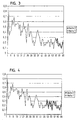
- FIG. 3 shows an exemplary undisturbed echo profile of the electromagnetic pulse with field strength changes resulting from an initial entry into the monitored area in the outer area of the larger distances or spherical shells. With the entry into the monitored area, changes in the field strengths occur only at the outside, while the field strengths in the inner area remain unchanged.
- FIG. 4 shows a representation of the echo profile comparable to that of FIG. 3 with field strength changes resulting from the further entry into the monitored area in an increasingly larger outer area. Compared to the representation according to FIG. 3, a larger outer area is thus affected by the field strength changes, but the field strengths in the inner area still remain unchanged.
- FIG. 5 shows a purely schematic representation of an exemplary embodiment of a sensor 10 of a monitoring system which is suitable in particular for motor vehicles.
- the generator 12 may operate periodically or aperiodically. This may be, for example, an e. in a range of about 1 to about 10 MHz working pulse generator.
- the transmission pulse generator 14 acts on a transmission antenna 16.
- the output signal of the generator 12 is simultaneously applied to a delay device 18, for example a delay line, which acts on a pulse generator 20 with a corresponding delay.
- a gate or sampling circuit 22 is driven, which supplies the signals received via a receiving antenna 24 to a filter 26, to which, for example, a microcontroller 28 is connected downstream.
- the delay generated by the device 18 can be set, for example, digitally or analogically via a microcontroller or a field-programmable gate array (FPGA) in order to forward the signal received via the receiving antenna 24 to the filter 26 at the correct time.
- a microcontroller or a field-programmable gate array (FPGA) in order to forward the signal received via the receiving antenna 24 to the filter 26 at the correct time.
- the filter 26 has the task of producing a low-frequency evaluable signal from the short sampling or sampling section.
- the filtered signal is amplified and then supplied to the microcontroller 28.
- the filter 26 Since the signals generated when entering the monitored area are very low-frequency, the filter 26 must have a very low lower limit frequency, which is for example about 2 Hz.
- FIG. 6 shows an echo profile comparable to that of FIG. 1, in which the respective position of the smaller or inner spherical shell 30 and of the larger or outer spherical shell 32 is indicated.
- the respectively correct potential can also be controlled, for example, by generating an average potential by switching over very quickly in the correct time relationship between two radii. The switching takes place on the basis of similar potentials that are once above and below the potential of the monitoring radius. This ensures that in each case there is a potential in between equal to the potential of the surveillance radius.
- the potential can be reliably determined in an inner and an outer spherical shell.
- the measured values of the inner spherical shell are subtracted from the measured value of a reference potential, or the measured values of the outer spherical shell are subtracted from the measured value of the reference spherical shell.
- the second auxiliary potential can be generated in exactly the same way as the first, although the selected radii must be independent of the potentials of the first auxiliary potential. For the rather rare case that no further pairing of auxiliary radii is found, the monitoring radius must be moved only one position inwards. This procedure can then be repeated until all conditions have been met.
- potential jumps can also be adjusted by a corresponding reduction of the transmission frequency.
- the transmission frequency is proportional to the height of the measured amplitude. If the amplitude is too high in comparison, the transmission frequency is reduced until a sufficient Meßwertanleich is reached, so that the respective spherical shell can be used alternately with the other spherical shells. Since the behavior here is not linear, the mechanism only works within a small range.
- a microcontroller can now by evaluating the signals on the feature of a possible internal interference To deduce whether there is a disturbance or indeed an intervention in the monitored area.
- the sensor shown in FIG. 5 may in particular be a short-distance radar (SDR) operating in the high-frequency range, in particular for interior protection.
- SDR short-distance radar
Landscapes
- Engineering & Computer Science (AREA)
- Radar, Positioning & Navigation (AREA)
- Remote Sensing (AREA)
- Mechanical Engineering (AREA)
- Computer Networks & Wireless Communication (AREA)
- Physics & Mathematics (AREA)
- General Physics & Mathematics (AREA)
- Radar Systems Or Details Thereof (AREA)
Claims (11)
- Système de surveillance destiné en particulier aux véhicules, avec au moins un capteur (10) prévu en guise d'unité radar qui émet des signaux radar par impulsions et reçoit des signaux radar réfléchis dans une zone à surveiller qui sont utilisés pour détecter les intrusions dans la zone surveillée, caractérisé en ce que, pour identifier les intrusions dans la zone surveillée sont utilisés des signaux radar qui ont été réfléchis à une grande distance définie du capteur (10) à l'intérieur de la zone surveillée, ou sur une enveloppe sphérique (32) définie d'un grand rayon approprié, en ce que, pour identifier les parasites sont utilisés des signaux radar qui ont été réfléchis à une petite distance définie du capteur, ou sur une enveloppe sphérique (30) définie d'un petit rayon approprié, et en ce que les valeurs de mesure obtenues pour la petite distante ou la petite enveloppe sphérique (30) sont comparées avec les valeurs de mesure obtenues pour la grande distance et la grande enveloppe (32) et le résultat de la comparaison est utilisé pour décider de la présence d'un parasite ou d'une intrusion dans la zone surveillée.
- Système de surveillance selon la revendication 1, caractérisé en ce que sont prévus des moyens pour régler les différentes distances ou enveloppes sphériques (30, 32) sur une fenêtre temporelle de réception temporisée de manière appropriée par rapport à une fenêtre temporelle d'émission correspondante.
- Système de surveillance selon la revendication 1 ou 2, caractérisé en ce que le capteur (10) est réglable de telle sorte qu'en l'absence de parasite et d'intrusion dans la zone surveillée, il y a sensiblement le même potentiel électrique pour la grande distance concernée ou la grande enveloppe sphérique (32) concernée et la petite distance concernée ou la petite enveloppe sphérique (30) concernée.
- Système de surveillance selon l'une quelconque des revendications précédentes, caractérisé en ce que, pour générer le potentiel électrique associé à une petite distance ou à une petite enveloppe sphérique (30), est généré un potentiel électrique moyen en alternant entre deux petites distances ou enveloppes sphériques dont le potentiel électrique est inférieur ou supérieur au potentiel électrique associé à la grande distance ou à la grande enveloppe sphérique (32).
- Système de surveillance selon la revendication 4, caractérisé en ce que le potentiel électrique moyen est aligné sur le potentiel électrique associé à la grande distance ou à la grande enveloppe sphérique (32) en alternant dans un rapport temporel correspondant entre les deux petites distances ou enveloppes sphériques.
- Système de surveillance selon l'une quelconque des revendications précédentes, caractérisé en ce que le potentiel électrique associé à la petite distance ou à la petite enveloppe sphérique (30) est aligné par une fréquence d'émission réglable en conséquence sur le potentiel électrique associé à la grande distance ou à la grande enveloppe sphérique (32).
- Système de surveillance selon l'une quelconque des revendications précédentes, caractérisé en ce que, hormis le potentiel électrique associé à une petite distance ou une petite enveloppe sphérique (30), est généré un autre potentiel électrique auxiliaire associé à une autre petite distance ou une autre petite enveloppe sphérique.
- Système de surveillance selon la revendication 7, caractérisé en ce que le capteur est réglable de telle sorte qu'en l'absence de parasite et d'intrusion dans la zone surveillée, l'autre potentiel auxiliaire électrique est au moins sensiblement égal au potentiel électrique associé à la grande distance ou à la grande enveloppe sphérique (32).
- Système de surveillance selon la revendication 7 ou 8, caractérisé en ce que, pour générer l'autre potentiel auxiliaire électrique, on génère un potentiel électrique moyen en alternant entre deux petites distances ou enveloppes sphériques dont le potentiel électrique est inférieur ou supérieur au potentiel électrique associé à la grande distance ou à la grande enveloppe sphérique (32).
- Système de surveillance selon la revendication 9, caractérisé en ce que l'autre potentiel électrique moyen est aligné sur le potentiel électrique associé à la grande distance ou à la grande enveloppe sphérique (32) en alternant dans un rapport temporel correspondant entre les deux petites distances ou enveloppes sphériques.
- Système de surveillance selon l'une quelconque des revendications précédentes, caractérisé en ce que l'autre potentiel électrique est aligné par une fréquence d'émission réglable en conséquence sur le potentiel électrique associé à la grande distance ou à la grande enveloppe sphérique (32).
Applications Claiming Priority (2)
| Application Number | Priority Date | Filing Date | Title |
|---|---|---|---|
| DE10125311 | 2001-05-23 | ||
| DE2001125311 DE10125311A1 (de) | 2001-05-23 | 2001-05-23 | Überwachungssystem |
Publications (3)
| Publication Number | Publication Date |
|---|---|
| EP1262384A2 EP1262384A2 (fr) | 2002-12-04 |
| EP1262384A3 EP1262384A3 (fr) | 2003-04-23 |
| EP1262384B1 true EP1262384B1 (fr) | 2006-10-04 |
Family
ID=7685984
Family Applications (1)
| Application Number | Title | Priority Date | Filing Date |
|---|---|---|---|
| EP02010876A Expired - Fee Related EP1262384B1 (fr) | 2001-05-23 | 2002-05-15 | Système radar pour surveiller l'intérieur d'un véhicule |
Country Status (2)
| Country | Link |
|---|---|
| EP (1) | EP1262384B1 (fr) |
| DE (2) | DE10125311A1 (fr) |
Families Citing this family (1)
| Publication number | Priority date | Publication date | Assignee | Title |
|---|---|---|---|---|
| JP4096861B2 (ja) * | 2003-11-04 | 2008-06-04 | オムロン株式会社 | 検出装置 |
Citations (4)
| Publication number | Priority date | Publication date | Assignee | Title |
|---|---|---|---|---|
| EP0482401A1 (fr) * | 1990-10-23 | 1992-04-29 | Kabelwerke Reinshagen GmbH | Procédé de surveillance ultrasonore des volumes, en particulier dans des véhicules à moteur |
| DE19732776C1 (de) * | 1997-07-30 | 1999-02-11 | Leuze Electronic Gmbh & Co | Optoelektronische Vorrichtung |
| US5936524A (en) * | 1996-05-02 | 1999-08-10 | Visonic Ltd. | Intrusion detector |
| DE19929794A1 (de) * | 1998-07-03 | 2000-01-13 | Toyota Motor Co Ltd | Fahrzeug-Radarvorrichtung |
Family Cites Families (10)
| Publication number | Priority date | Publication date | Assignee | Title |
|---|---|---|---|---|
| US4673935A (en) * | 1984-01-26 | 1987-06-16 | The Boeing Company | Instrusion detection system |
| DE3479159D1 (en) * | 1984-04-13 | 1989-08-31 | Siemens Ag | Microwave intrusion detection system |
| EP0188757A1 (fr) * | 1984-12-20 | 1986-07-30 | Siemens Aktiengesellschaft | Dispositif micro-ondes de détection d'intrusion |
| DE19521511C1 (de) * | 1995-06-13 | 1997-02-20 | Megamos F & G Sicherheit | Verfahren zur Ultraschallüberwachung, insbesondere von Innenräumen von Kraftfahrzeugen |
| GB9608368D0 (en) * | 1996-04-23 | 1996-06-26 | Philips Electronics Nv | Object detecting apparatus |
| GB9613645D0 (en) * | 1996-06-28 | 1996-08-28 | Cambridge Consultants | Vehicle radar system |
| DE19749747A1 (de) * | 1997-11-11 | 1999-05-12 | Grundig Ag | Autradioalarmanlage |
| DE19813631A1 (de) * | 1998-03-27 | 1999-10-07 | Honeywell Ag | Radar-Entfernungsmesser |
| US6208248B1 (en) * | 1999-01-28 | 2001-03-27 | Anro Engineering, Inc. | Quick response perimeter intrusion detection sensor |
| EP1031853A3 (fr) * | 1999-02-27 | 2001-04-25 | Delphi Technologies, Inc. | Capteurs et système radar pour surveillance d'un espace |
-
2001
- 2001-05-23 DE DE2001125311 patent/DE10125311A1/de not_active Withdrawn
-
2002
- 2002-05-15 EP EP02010876A patent/EP1262384B1/fr not_active Expired - Fee Related
- 2002-05-15 DE DE50208311T patent/DE50208311D1/de not_active Expired - Fee Related
Patent Citations (4)
| Publication number | Priority date | Publication date | Assignee | Title |
|---|---|---|---|---|
| EP0482401A1 (fr) * | 1990-10-23 | 1992-04-29 | Kabelwerke Reinshagen GmbH | Procédé de surveillance ultrasonore des volumes, en particulier dans des véhicules à moteur |
| US5936524A (en) * | 1996-05-02 | 1999-08-10 | Visonic Ltd. | Intrusion detector |
| DE19732776C1 (de) * | 1997-07-30 | 1999-02-11 | Leuze Electronic Gmbh & Co | Optoelektronische Vorrichtung |
| DE19929794A1 (de) * | 1998-07-03 | 2000-01-13 | Toyota Motor Co Ltd | Fahrzeug-Radarvorrichtung |
Also Published As
| Publication number | Publication date |
|---|---|
| EP1262384A2 (fr) | 2002-12-04 |
| DE10125311A1 (de) | 2002-11-28 |
| EP1262384A3 (fr) | 2003-04-23 |
| DE50208311D1 (de) | 2006-11-16 |
Similar Documents
| Publication | Publication Date | Title |
|---|---|---|
| EP1936400B1 (fr) | Lecteur laser | |
| EP2469296B1 (fr) | Capteur optoélectronique et procédé destiné à la détection et la détermination de l'éloignement d'objets | |
| EP2824478B1 (fr) | Capteur optoélectronique et procédé destiné à la détection d'objets et à la détermination de distance dans une zone de surveillance | |
| EP2541273B1 (fr) | Détection et détermination de distance d'objets | |
| EP1261792B1 (fr) | Procede d'emission et de reception, en particulier pour la detection d'un indicateur d'identite | |
| EP3139139B1 (fr) | Appareil de mesure de niveau de remplissage avec mode de détection de signaux parasites | |
| EP1952179B1 (fr) | Procede pour operations de detection de l'environnement | |
| DE102013218571A1 (de) | Vorrichtung und Verfahren zur seitlichen Umfelderfassung eines Kraftfahrzeugs | |
| EP2942644A1 (fr) | Capteur télémétrique et procédé destiné à la détection et la détermination de l'éloignement d'objets | |
| EP2867693A1 (fr) | Procédé et dispositif de mesure de distance | |
| WO1998038616A1 (fr) | Dispositif et procede pour detecter un objet dans une zone predetermine, notamment des vehicules, aux fins de la surveillance du trafic. | |
| EP3220164B1 (fr) | Procédé de fonctionnement d'un capteur écartométrique de surveillance et capteur écartométrique de surveillance | |
| DE102018200688B4 (de) | Verfahren und Vorrichtung zum Betreiben eines akustischen Sensors | |
| EP1262384B1 (fr) | Système radar pour surveiller l'intérieur d'un véhicule | |
| EP2977786B1 (fr) | Capteur telemetrique destine a la detection et la determination de l'eloignement d'objets | |
| EP2278360B1 (fr) | Procédé de fonctionnement d'un capteur optique | |
| WO2019101506A1 (fr) | Procédé de fonctionnement d'un capteur lidar et capteur lidar | |
| EP1529342B1 (fr) | Procede de deparasitage de signaux de mesure | |
| EP1451614B1 (fr) | Procede de correction de lumiere parasite dans un ensemble capteur optique | |
| DE102004032048A1 (de) | Verfahren und Vorrichtung zur Bestimmung der Ausrichtung eines ersten Objektes zu einem zweiten Objekt | |
| DE202014103348U1 (de) | Entfernungsmessender Sensor zur Erfassung und Abstandsbestimmung von Objekten | |
| WO2017025602A1 (fr) | Capteur de proximité et procédé de détection de la proximité d'un élément d'habillage intérieur d'un véhicule | |
| EP2910972B1 (fr) | Capteur mesurant l'éloignement et procédé destiné à la détermination de distance d'objets dans une zone de surveillance | |
| DE102020133095A1 (de) | Verfahren zur Bestimmung einer Distanz zwischen einer Messvorrichtung und einem Objekt | |
| DE102010064682B3 (de) | Optoelektronischer Sensor und Verfahren zur Erfassung und Abstandsbestimmung von Objekten |
Legal Events
| Date | Code | Title | Description |
|---|---|---|---|
| PUAI | Public reference made under article 153(3) epc to a published international application that has entered the european phase |
Free format text: ORIGINAL CODE: 0009012 |
|
| AK | Designated contracting states |
Kind code of ref document: A2 Designated state(s): AT BE CH CY DE DK ES FI FR GB GR IE IT LI LU MC NL PT SE TR |
|
| AX | Request for extension of the european patent |
Free format text: AL;LT;LV;MK;RO;SI |
|
| PUAL | Search report despatched |
Free format text: ORIGINAL CODE: 0009013 |
|
| AK | Designated contracting states |
Designated state(s): AT BE CH CY DE DK ES FI FR GB GR IE IT LI LU MC NL PT SE TR |
|
| AX | Request for extension of the european patent |
Extension state: AL LT LV MK RO SI |
|
| 17P | Request for examination filed |
Effective date: 20030527 |
|
| AKX | Designation fees paid |
Designated state(s): DE FR GB IT SE |
|
| 17Q | First examination report despatched |
Effective date: 20040212 |
|
| GRAP | Despatch of communication of intention to grant a patent |
Free format text: ORIGINAL CODE: EPIDOSNIGR1 |
|
| GRAS | Grant fee paid |
Free format text: ORIGINAL CODE: EPIDOSNIGR3 |
|
| GRAA | (expected) grant |
Free format text: ORIGINAL CODE: 0009210 |
|
| AK | Designated contracting states |
Kind code of ref document: B1 Designated state(s): DE FR GB IT SE |
|
| PG25 | Lapsed in a contracting state [announced via postgrant information from national office to epo] |
Ref country code: IT Free format text: LAPSE BECAUSE OF FAILURE TO SUBMIT A TRANSLATION OF THE DESCRIPTION OR TO PAY THE FEE WITHIN THE PRESCRIBED TIME-LIMIT;WARNING: LAPSES OF ITALIAN PATENTS WITH EFFECTIVE DATE BEFORE 2007 MAY HAVE OCCURRED AT ANY TIME BEFORE 2007. THE CORRECT EFFECTIVE DATE MAY BE DIFFERENT FROM THE ONE RECORDED. Effective date: 20061004 |
|
| REG | Reference to a national code |
Ref country code: GB Ref legal event code: FG4D Free format text: NOT ENGLISH |
|
| REF | Corresponds to: |
Ref document number: 50208311 Country of ref document: DE Date of ref document: 20061116 Kind code of ref document: P |
|
| PG25 | Lapsed in a contracting state [announced via postgrant information from national office to epo] |
Ref country code: SE Free format text: LAPSE BECAUSE OF FAILURE TO SUBMIT A TRANSLATION OF THE DESCRIPTION OR TO PAY THE FEE WITHIN THE PRESCRIBED TIME-LIMIT Effective date: 20070104 |
|
| GBV | Gb: ep patent (uk) treated as always having been void in accordance with gb section 77(7)/1977 [no translation filed] |
Effective date: 20061004 |
|
| ET | Fr: translation filed | ||
| PLBE | No opposition filed within time limit |
Free format text: ORIGINAL CODE: 0009261 |
|
| STAA | Information on the status of an ep patent application or granted ep patent |
Free format text: STATUS: NO OPPOSITION FILED WITHIN TIME LIMIT |
|
| 26N | No opposition filed |
Effective date: 20070705 |
|
| PG25 | Lapsed in a contracting state [announced via postgrant information from national office to epo] |
Ref country code: GB Free format text: LAPSE BECAUSE OF FAILURE TO SUBMIT A TRANSLATION OF THE DESCRIPTION OR TO PAY THE FEE WITHIN THE PRESCRIBED TIME-LIMIT Effective date: 20061004 |
|
| PGFP | Annual fee paid to national office [announced via postgrant information from national office to epo] |
Ref country code: DE Payment date: 20080522 Year of fee payment: 7 |
|
| PGFP | Annual fee paid to national office [announced via postgrant information from national office to epo] |
Ref country code: IT Payment date: 20080527 Year of fee payment: 7 |
|
| REG | Reference to a national code |
Ref country code: FR Ref legal event code: ST Effective date: 20100129 |
|
| PG25 | Lapsed in a contracting state [announced via postgrant information from national office to epo] |
Ref country code: FR Free format text: LAPSE BECAUSE OF NON-PAYMENT OF DUE FEES Effective date: 20090602 |
|
| PGFP | Annual fee paid to national office [announced via postgrant information from national office to epo] |
Ref country code: FR Payment date: 20080514 Year of fee payment: 7 |
|
| PG25 | Lapsed in a contracting state [announced via postgrant information from national office to epo] |
Ref country code: DE Free format text: LAPSE BECAUSE OF NON-PAYMENT OF DUE FEES Effective date: 20091201 |
|
| PG25 | Lapsed in a contracting state [announced via postgrant information from national office to epo] |
Ref country code: IT Free format text: LAPSE BECAUSE OF NON-PAYMENT OF DUE FEES Effective date: 20090515 |