EP1262052B1 - Technique de compression d'un champ d'en-tete dans un paquet de donnees - Google Patents
Technique de compression d'un champ d'en-tete dans un paquet de donnees Download PDFInfo
- Publication number
- EP1262052B1 EP1262052B1 EP01916516A EP01916516A EP1262052B1 EP 1262052 B1 EP1262052 B1 EP 1262052B1 EP 01916516 A EP01916516 A EP 01916516A EP 01916516 A EP01916516 A EP 01916516A EP 1262052 B1 EP1262052 B1 EP 1262052B1
- Authority
- EP
- European Patent Office
- Prior art keywords
- header
- rtp
- packet
- jitter
- current
- Prior art date
- Legal status (The legal status is an assumption and is not a legal conclusion. Google has not performed a legal analysis and makes no representation as to the accuracy of the status listed.)
- Expired - Lifetime
Links
- 238000000034 method Methods 0.000 title claims abstract description 84
- 230000006835 compression Effects 0.000 claims abstract description 44
- 238000007906 compression Methods 0.000 claims abstract description 44
- 230000005540 biological transmission Effects 0.000 claims description 18
- 230000000694 effects Effects 0.000 claims description 18
- 230000009467 reduction Effects 0.000 abstract description 11
- 238000004891 communication Methods 0.000 abstract description 3
- 230000008859 change Effects 0.000 description 31
- 230000006837 decompression Effects 0.000 description 26
- 238000010586 diagram Methods 0.000 description 26
- 230000001052 transient effect Effects 0.000 description 24
- 230000001186 cumulative effect Effects 0.000 description 23
- 238000012546 transfer Methods 0.000 description 22
- 230000008569 process Effects 0.000 description 19
- 230000006870 function Effects 0.000 description 17
- 230000003068 static effect Effects 0.000 description 10
- 238000013459 approach Methods 0.000 description 9
- 230000001413 cellular effect Effects 0.000 description 9
- 238000004364 calculation method Methods 0.000 description 6
- 238000002360 preparation method Methods 0.000 description 6
- 230000008929 regeneration Effects 0.000 description 6
- 238000011069 regeneration method Methods 0.000 description 6
- 230000008901 benefit Effects 0.000 description 5
- 230000001360 synchronised effect Effects 0.000 description 5
- 230000006399 behavior Effects 0.000 description 4
- 230000000875 corresponding effect Effects 0.000 description 4
- 230000011664 signaling Effects 0.000 description 4
- 230000002159 abnormal effect Effects 0.000 description 3
- 150000001875 compounds Chemical class 0.000 description 3
- 230000001419 dependent effect Effects 0.000 description 3
- 238000013461 design Methods 0.000 description 3
- 238000007726 management method Methods 0.000 description 3
- 230000007246 mechanism Effects 0.000 description 3
- 238000005457 optimization Methods 0.000 description 3
- 230000002596 correlated effect Effects 0.000 description 2
- 238000013213 extrapolation Methods 0.000 description 2
- 238000012986 modification Methods 0.000 description 2
- 230000004048 modification Effects 0.000 description 2
- 238000012545 processing Methods 0.000 description 2
- 238000013139 quantization Methods 0.000 description 2
- 230000007704 transition Effects 0.000 description 2
- 238000011144 upstream manufacturing Methods 0.000 description 2
- 241000478345 Afer Species 0.000 description 1
- 102100032813 Hepatocyte growth factor-like protein Human genes 0.000 description 1
- 101001066435 Homo sapiens Hepatocyte growth factor-like protein Proteins 0.000 description 1
- 101000880431 Homo sapiens Serine/threonine-protein kinase 4 Proteins 0.000 description 1
- 101001042190 Medicago scutellata Bowman-Birk type proteinase inhibitor Proteins 0.000 description 1
- 240000004760 Pimpinella anisum Species 0.000 description 1
- 238000004458 analytical method Methods 0.000 description 1
- 230000003139 buffering effect Effects 0.000 description 1
- 238000012937 correction Methods 0.000 description 1
- 230000007423 decrease Effects 0.000 description 1
- 230000003247 decreasing effect Effects 0.000 description 1
- 230000001934 delay Effects 0.000 description 1
- 238000001514 detection method Methods 0.000 description 1
- 238000011156 evaluation Methods 0.000 description 1
- 238000012886 linear function Methods 0.000 description 1
- 238000007670 refining Methods 0.000 description 1
- 230000004044 response Effects 0.000 description 1
- 230000003595 spectral effect Effects 0.000 description 1
- 239000002699 waste material Substances 0.000 description 1
Images


Classifications
-
- H—ELECTRICITY
- H04—ELECTRIC COMMUNICATION TECHNIQUE
- H04L—TRANSMISSION OF DIGITAL INFORMATION, e.g. TELEGRAPHIC COMMUNICATION
- H04L69/00—Network arrangements, protocols or services independent of the application payload and not provided for in the other groups of this subclass
- H04L69/04—Protocols for data compression, e.g. ROHC
-
- H—ELECTRICITY
- H04—ELECTRIC COMMUNICATION TECHNIQUE
- H04L—TRANSMISSION OF DIGITAL INFORMATION, e.g. TELEGRAPHIC COMMUNICATION
- H04L65/00—Network arrangements, protocols or services for supporting real-time applications in data packet communication
- H04L65/80—Responding to QoS
-
- H—ELECTRICITY
- H04—ELECTRIC COMMUNICATION TECHNIQUE
- H04L—TRANSMISSION OF DIGITAL INFORMATION, e.g. TELEGRAPHIC COMMUNICATION
- H04L47/00—Traffic control in data switching networks
- H04L47/10—Flow control; Congestion control
- H04L47/43—Assembling or disassembling of packets, e.g. segmentation and reassembly [SAR]
-
- H—ELECTRICITY
- H04—ELECTRIC COMMUNICATION TECHNIQUE
- H04L—TRANSMISSION OF DIGITAL INFORMATION, e.g. TELEGRAPHIC COMMUNICATION
- H04L65/00—Network arrangements, protocols or services for supporting real-time applications in data packet communication
- H04L65/1066—Session management
- H04L65/1101—Session protocols
-
- H—ELECTRICITY
- H04—ELECTRIC COMMUNICATION TECHNIQUE
- H04L—TRANSMISSION OF DIGITAL INFORMATION, e.g. TELEGRAPHIC COMMUNICATION
- H04L65/00—Network arrangements, protocols or services for supporting real-time applications in data packet communication
- H04L65/60—Network streaming of media packets
- H04L65/65—Network streaming protocols, e.g. real-time transport protocol [RTP] or real-time control protocol [RTCP]
-
- H—ELECTRICITY
- H04—ELECTRIC COMMUNICATION TECHNIQUE
- H04L—TRANSMISSION OF DIGITAL INFORMATION, e.g. TELEGRAPHIC COMMUNICATION
- H04L65/00—Network arrangements, protocols or services for supporting real-time applications in data packet communication
- H04L65/60—Network streaming of media packets
- H04L65/70—Media network packetisation
-
- H—ELECTRICITY
- H04—ELECTRIC COMMUNICATION TECHNIQUE
- H04L—TRANSMISSION OF DIGITAL INFORMATION, e.g. TELEGRAPHIC COMMUNICATION
- H04L69/00—Network arrangements, protocols or services independent of the application payload and not provided for in the other groups of this subclass
- H04L69/22—Parsing or analysis of headers
-
- H—ELECTRICITY
- H04—ELECTRIC COMMUNICATION TECHNIQUE
- H04L—TRANSMISSION OF DIGITAL INFORMATION, e.g. TELEGRAPHIC COMMUNICATION
- H04L9/00—Cryptographic mechanisms or cryptographic arrangements for secret or secure communications; Network security protocols
- H04L9/40—Network security protocols
Definitions
- the present invention relates to a method and apparatus for compressing a header field in a data packet. More particularly, the present invention relates to a method and apparatus for compressing a header field of a data packet using a Timer and a Reference Based Scheme.
- IP Internet Protocol
- RTP Real-Time Transfer Protocol
- UDP/ IP User Datagram Protocol
- RTP is described in detail in RFC 1889.
- the size of the combined IP/UDP/RTP headers is at least 40 bytes for IPv4 and at least 60 bytes for IPv6.
- 40-60 bytes overhead per packet may be considered heavy in systems (e.g., such as cellular networks) where spectral efficiency is a primary concern. Consequently, a need exists for suitable IP/UDP/RTP header compression mechanisms.
- a current header compression scheme is described in RFC2508, which is able to compress the 40/60 byte IP/UDP/RTP header down to 2 or 4 bytes over point-to-point links.
- the existing header compression algorithms are based on the observation that most fields of the IP packet headers remain constant in a packet stream during the length of a session. Thus, it is possible to compress the header information by establishing a compression state (the full header information) at the de-compressor and by simply carrying minimal amount of header information from the compressor to the de-compressor.
- RFC2508 is based on the idea that most of the time, the RTP fields that change from one packet to the next, such as the RTP time stamp, can be predicted by linear extrapolation. Essentially the only information that has to be sent is a sequence number, used for error and packet loss detection (as well as a context ID). When the sender determines that linear extrapolation cannot be applied to the current packet, a first order difference information with respect to the immediately preceding packet is sent. To initiate the session, a full header is sent.
- the receiver determines that there is packet loss (as detected by a sequence number incrementing by more than 1) the receiver will explicitly request the sender to transmit the full header in order to allow a re-synchronization such a compression of algorithm is for example described in citation "Evaluation of the Casner-Jacobson Algorithm for compressing the RTP/UCP/IP Headers", G. Mamais.
- the header compression defined in RFC2508 is not well suited for certain environments (such as cellular or wireless environments), where bandwidth is at a premium and errors are common.
- the RTP time stamp is assumed to have most of the time a linearly increasing pattern. When the header conforms to the pattern, essentially only a short sequence number is needed in the compressed header. When the header does not conform to the pattern, the difference between the RTP time stamps of the current header and of the previous one is sent in the compressed header. Further optimization is possible by using a coding table. This approach has three drawbacks. The first one is that it is not robust to errors, as the loss of the previous header will invalidate the decompression of the current header.
- the second one is that RTP time stamp differences or jumps can be very large, thus overflowing the coding look up table. For example, if the medium is voice, such large differences can be caused by a silence interval.
- the third one is that the size of the resulting encoded difference is variable, which makes it more difficult to predict and manage the bandwidth to be allocated.
- the present invention relates to a method has defined by the appended claims.
- a timer based header decompression technique is provided.
- An RTP source generates a header field, such as an RTP time stamp.
- the time stamp is sent over a network to a compressor.
- a jitter reduction function JRF
- JRF jitter reduction function
- the compressor calculates a compressed header field (compressed time stamp) based on the RTP time stamp and an initial value of the time stamp.
- the compressed time stamp represents jitter which is calculated as an effect the network between the source and the decompressor has on the transmission of packets.
- the calculated jitter is a cumulation of network jitter representing the effect the network between the source and the compressor has on the transmission of packets and radio jitter representing the effect the network between the compressor and decompressor has on the transmission of packets.
- network as used herein is intended to be a broad term so as not to preclude, for example, radio links in a wireless telecommunications network.
- the RTP packet, including the compressed time stamp, is then transmitted over a link or network to a decompressor.
- the decompressor decompresses the compressed time stamp by first calculating an estimate or approximation of the time stamp based on the current value of a timer located at the terminal (i.e., based on elapsed time). The approximation of the time stamp is then refined or corrected based on the compressed time stamp provided in the packet header. In this manner, the time stamp for the current packet (header) is regenerated based on a local timer and a compressed time stamp provided in the current header. The packet and the regenerated time stamp are then provided to an RTP endpoint for processing.
- the timer-based scheme of the present invention includes several advantages.
- the term "timer based scheme" as used herein is inclusive of the timer based scheme using a compressed time stamp and the timer and reference based scheme as disclosed herein.
- the size of the compressed time stamp (or other header field) is constant and small. Furthermore, the size does not change as a function of the length of interval of silence. No synchronization is required between the timer process at the RTP source (generating the time stamp) and the timer at the decompressor process. Also, this technique is robust to errors, as the partial time stamp information in the compressed header is self contained and only needs to be combined with the decompressor timer value to yield the full RTP time stamp value. Loss or corruption of a header will not invalidate subsequent compressed headers.
- a second example of the present invention provides a header-stripping scheme in which the header (e.g., including the RTP time stamp) is stripped or removed from the RTP packet prior to transmission.
- a header stripper and a header generator are connected through a circuit like connection (e.g., circuit or virtual circuit) or an essentially constant bit rate channel.
- the header stripper strips or removes the header (including removing the time stamp and sequence number) from each packet and then transmits the headerless packets to the header regenerator.
- the packets can be transmitted at a time spacing according to the RTP time stamp (TS) in the header. Therefore, in this example, the time stamp is not explicitly provided in the RTP packet (nor even a compressed time stamp). Rather, timing information is implicitly provided to the to the header regenerator based upon an essentially constant bit-rate channel between the header stripper and regenerator.
- the essentially constant bit-rate channel can be provided in several different ways.
- the header regenerator can regenerate the time stamps for sequential packets by incrementing a local time stamp counter by TS_stride every T msecs, and regenerate the packet sequence numbers by incrementing a local SN counter by I every packet duration.
- These fields can be regenerated based only on a local timer or counter due to the essentially constant bit rate channel provided between the header stripper and header regenerator in which no packet jitter is introduced. Therefore, after initialization, these header fields can be regenerated at the header regenerator with reference only to a local clock.
- one or more basic discontinuity events may occur which, if not addressed, could likely invalidate the header-stripping approach which relies only on a local timer or clock for field regeneration.
- a header string is a sequence of packet headers having known or linearly predictable fields. The transition from one string to another can be caused by any of several discontinuity events. When this occurs, the header stripper identifies discontinuity event and sends updated header information related to the event to the header regenerator to allow time stamp and sequence number regeneration to continue.
- a similar technique of providing updated header information can be used when there is a handover as well.
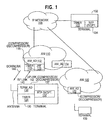
- Fig. 1 is a block diagram illustrating an system according to an example embodiment of the present invention.
- a terminal 102 is connected to a IP network 108.
- Terminal 102 may be a personal computer or the like running RTP/UDP/IP, and providing packetized voice samples in RTP packets for transmission over network 110.
- Terminal 102 includes a RTP endpoint 104 which identifies this terminal (e.g., including IP address, port number, etc.) as either a source or destination for RTP packets.
- IP network is provided as an example, however, other types of packet switched networks or the like can be used instead. It should be noted that the term "network" as used herein is intended to be a broad term so as not to preclude, for example, radio links in a wireless telecommunications network.
- Terminal 102 also includes a local timer 103 for generating a time stamp.
- An access network infrastructure (ANI) 110 is connected to IP network 108.
- a wireless terminal 130 is coupled via radio frequency (RF) link 140 to ANI 110.
- the wireless terminal 130 as described herein could, for example, be a wireless compressor or a wireless decompressor depending on its environment. This particularly occurs when the source of the packets or the destination of the packets are separate from the wireless terminal 130.
- RF link 140 includes an uplink 142 (from terminal 130 to ANI 110) and a downlink 144 (from ANI 110 to terminal 130).
- ANI 110 interfaces one or more wireless (or radio frequency) terminals (including terminal 130) in a region to IP network 108, including converting between wireline signals (provided from IP network 108) and wireless or RF signals (provided to or from terminal 130).
- ANI 110 allows RTP packets received from IP network 108 to be sent over RF link 140 to wireless terminal 130, and allows RTP packets from terminal 130 to be sent over IP network 108 to another terminal, such as terminal 102.
- ANI 110 includes one or more ANI adapters (ANI_AD), such as ANI_AD 112 and ANI_AD 114, each of which preferably includes a timer.
- ANI_AD performs header compression (prior to downlink transmission) and decompression (after uplink transmission). Headers (or one or more header fields, such as a time stamp) for RTP packets received from IP network 108 are compressed by ANI_AD 112 prior to transmission to terminal 130 over downlink 142, and packet headers received from terminal 130 are decompressed by ANI_AD 112 before transmission to IP network 108. Therefore, each ANI_AD may be considered to be a compressor/decompressor 115.
- Each ANI_AD may interface terminals located in a specific or different area within the region to IP network 108.
- ANI_AD 112 includes a timer 113 for implementing a timer-based decompression technique.
- ANI_AD 112 also includes a jitter reduction function (JRF) 115 which operates to measure the jitter on packets (or headers) received over the network 108 and discard any packets/headers which have excessive jitter.
- JRF jitter reduction function
- ANI 120 may be provided for interfacing other terminals located in additional regions to IP network 108.
- ANI 120 similarly includes one or more ANI_ADs, such as ANI_AD 122 ( Fig. 1 ). Each ANI_AD includes a timer and a JRF.
- Terminal 130 includes an RTP endpoint 132 which is a source and/or destination (receiver) for RTP packets.
- Terminal 130 includes a terminal adapter (term_AD) 136 which performs header compression (for packets to be transmitted uplink 142) and decompression (on packets received over downlink 144).
- terminal adapter (term_AD) may be considered to be a header compressor/decompressor 137, similar to the ANI_AD.
- the terminal adapter (term_AD) 136 also includes a timer 134 (a receiver timer) for calculating an approximation (or estimate) of a RTP time stamp of a current header.
- the terminal adapter (term_AD) 136 uses additional information in the RTP header to refine or correct the time stamp approximation.
- the time stamp approximation is corrected or adjusted based upon a compressed time stamp provided in the RTP header. In this manner, a local timer and a compressed time stamp can be used to regenerate the correct time stamp for each RTP header.
- Other terminals (such as terminal 150) may be provided, each including its own RTP endpoint, terminal adapter and timer.
- Fig. 1 simply provides one example where RTP data is transmitted over a data link or system (such as wireless link 140) where bandwidth is at a premium and errors are not uncommon.
- the present invention is not limited to a wireless link, but is applicable to a wide variety of links (including wireline links, etc.).
- VoIP Voice over IP
- ANI_AD would interface the IP network to a computer terminal running RTP/UDP/IP (e.g., terminal 130) and having a cellular or RF interface for receiving RTP packets over the wireless or RF link.
- RTP/UDP/IP e.g., terminal 130
- Fig. 2 is a diagram illustrating an uncompressed format of an RTP packet according to an example of the present invention.
- the uncompressed RTP packet includes an IP header, a UDP header 212, a RTP header 214 and a payload which could be a voice sample 216.
- Fig. 3 is a diagram illustrating the uncompressed RTP header format according to an example embodiment of the present invention.
- the uncompressed RTP header includes a time stamp (TS) 310, a sequence number (S.N.) 312 and some other fields 314. Due to the packet-switched nature of IP network 108, RTP packets can arrive out of order.
- the sequence number 312 is used at the RTP receiver or RTP destination (e.g., terminal 130, Fig. 1 ) to assemble the RTP voice samples in the correct order.
- the sequence numbers in the RTP packets will not reflect any non-linear change in the field (e.g., intervals of silence of the voice signal). Therefore, a time stamp (TS) 310 is provided to indicate the relative timing of each packet.
- TS time stamp
- the header compression technique described in RFC 2508 initially sends a complete (uncompressed) RTP packet, including all fields to the RTP destination/receiver. Many of the fields of the headers during a connection are static, and thus, need not be transmitted after the initial packet is sent and received. For most packets, only the sequence number and the time stamp will change from packet to packet. According to RFC 2508, the non-static fields (e.g., time stamp and sequence number) are updated at the receiver by adding (fixed) first-order differences to the previous values of those fields stored at the receiver. For example, the sequence number of each received RTP packet will automatically be incremented by one for each packet.
- the non-static fields e.g., time stamp and sequence number
- a technique for header compression is provided that can be used to more effectively compress a RTP time stamp (or other field) of a packet header.
- the compression scheme can accommodate an arbitrary jump in the RTP time stamp value, while yielding a constant size compressed RTP header (or constant size RTP time stamp).
- Fig. 4 is a diagram illustrating a compressed RTP header format according to an example embodiment of the present invention.
- the compressed RTP header may consist of a message type 410 which indicates the type of message, a bit mask 412 which identifies the fields which are changing, and a compressed time stamp field 414.
- the message type 410 may indicate a compressed time stamp if a compressed time stamp is provided in the packet header.
- the compressed time stamp field 414 includes the k least significant bits (lsbs) of a value which may indicate the time elapsed between packets.
- the compressed time stamp 414 may provide a portion (i.e., the k least significant bits) of a source counter value (or counter difference).
- the source counter may be used to generate the time stamp for each RTP packet header.
- Optional fields 416 can be used to provide updated or changed fields for those fields identified in the bit mask 412.
- an RTP packet is generated at an RTP endpoint (such as RTP endpoint 1 04 of terminal 102) and is addressed to another RTP endpoint.
- RTP endpoint 104 is the source of the one or more RTP packets to be sent to RTP endpoint 132 (the destination) of terminal 130.
- the RTP packet header includes a time stamp, which is generated at the RTP source (e.g., at terminal 102) based on a wall clock.
- the RTP packet is routed over the IP network 108 to the ANI_AD 112 of ANI 110.
- the ANI_AD 112 compresses one or more fields in the header(s) of the RTP packet.
- the ANI_AD compresses the RTP time stamp 310 ( Fig. 3 ) into a compressed time stamp 414 ( Fig. 4 ).
- Other fields in the header may be compressed by removing them or using some other technique.
- the RTP packet, including the compressed time stamp 414 is then transmitted over the downlink 144 of RF link 140 to terminal 130.
- the terminal adapter (term_AD) 136 of terminal 130 Upon receipt of the RTP packet with compressed header (i.e., compressed time stamp 414), the terminal adapter (term_AD) 136 of terminal 130 decompresses the time stamp value.
- the terminal adapter 136 decompresses the compressed time stamp 414 by first calculating an estimate or approximation of the time stamp based on the current value of timer 134. The approximation of the time stamp is then refined or corrected based on the compressed time stamp 414 provided in the packet header. In this manner, the time stamp for the current packet (header) is regenerated based on a local timer (timer 134) and a compressed time stamp provided in the current header.
- the other fields of the packet header (such as the sequence number) may also be regenerated.
- the packet and the regenerated time stamp are then provided to the RTP endpoint 132 for processing.
- the RTP endpoint 132 then replays the voice samples in the appropriate order (as specified by the sequence numbers) and having the appropriate timing as specified by the regenerated time stamps (e.g., to account for any intervals of silence).
- the ANI_AD 112 may also receive compressed headers (including a compressed time stamp) over RF link 140, and decompress the time stamp using the timer-based decompression technique described above. Therefore, the ANI_AD 112 may typically include a timer to allow the ANI_AD to decompress the compressed time stamp as described above. Similarly, the term_AD 136 of terminal 130 may also compress the time stamp of the RTP packet prior to transmission of the RTP packet over RF link 140 to ANI 110. To simplify the explanation of the example embodiments of the invention, the majority of the description will be directed to the downlink path 144. According to an example of the invention, RTP packets may be transmitted in both directions (uplink 142 and downlink 144).
- both ANI_AD 112 of ANI 110 and term_AD of terminal 130 may operate as a time stamp compressor (for transmission of the header/packet over the RF link) and a decompressor (after receipt of a compressed header received over RF link 140).
- Example embodiments of time stamp compression and decompression will be briefly described. It is assumed that the data in the RTP packets is voice data. The following variables and formulas are defined only to assist in explaining some of the features of the present invention, but the invention is not limited thereto. Also, the present invention is not limited to systems which use the same or similar types of variables, and is not limited to systems which perform the specific calculations described below. The variables and calculations are merely provided as an example embodiment of the invention.
- T - is the time spacing between RTP speech samples. (If there is one speech sample provided in each RTP packet, then T is also the spacing between RTP packet headers).
- TS_stride the RTP time stamp is incremented by TS_stride every T msec. In other words, the RTP time stamp increases by TS_stride for every new RTP packet.
- TS_stride is a constant (e.g., 100) that depends on the voice codec.
- TS_stride is provided to the receiver (terminal 130) and the ANI_AD 112.
- TS0 - RTP time stamp of the first header of a session received at the RTP receiver is considered a synchronization header because it is used for synchronization.
- TS0 is an initial value of the RTP time stamp provided to both the compressor (e.g., ANI_AD 112) and the decompressor (e.g., term_AD 136) at the beginning of the session (for synchronization).
- the compressor e.g., ANI_AD 112
- the decompressor e.g., term_AD 1366
- the ANI_AD and term_AD are initialized or synchronized by receiving an RTP packet with an uncompressed header (including an uncompressed time stamp providing TS0).
- the timer-based decompression technique requires providing an initial time stamp TS0 (e.g., through an initial or synchronization header that is uncompressed) to the time stamp compressor (i.e., ANI_AD 112) and to the decompressor (i.e., term_AD 136) before compressed headers can be properly decompressed (i.e., so the decompressor can correctly regenerate the time stamp).
- TS0 e.g., through an initial or synchronization header that is uncompressed
- the decompressor i.e., term_AD 1366
- m an integer that indicates the number of speech samples that have been sent. m is reset or cleared to 0 at the beginning of the session. m is proportional to (or indicates) the amount of time that has elapsed since the beginning of the session. m is incremented by I every T msecs.
- TS_current TS0 + m_current * TS_stride; The current time stamp for the current packet header.
- Receiver timer the timer at the RTP receiver (or RTP destination), such as the timer 134 of terminal 130.
- the local receiver timer is typically free running and will not be reset at the beginning of a session. Rather, elapsed time at the RTP receiver between receipt of two packet headers can be obtained by subtracting the timer value of the current header from the receiver timer value when the previous packet header was received.
- the receiver timer can be free running, one receiver timer can be shared by many flows or sessions. Alternatively, the receiver timer can be reset at the beginning of each session. Resetting or clearing a receiver timer at the beginning of a session (i.e., upon receipt of initialization header) would require a dedicated receiver timer (timer process) for each session or flow.
- the first uncompressed time stamp (TS0) of a session may be provided to the ANI_AD and the term_AD in an initialization header.
- the first header is provided to initialize the compressor (ANI_AD 112) and the decompressor (term_AD 136).
- the receiver timer is then incremented by 1 every T msecs.
- the ANI_AD 112 (compressor) uses the TS0 value to compress the time stamps of subsequent RTP packet headers.
- the term_AD 136 (decompressor) uses the TS0 value to decompress the compressed time stamp value (e.g., to regenerate the time stamps in subsequently received RTP headers).
- last_timer the value at the time at the receiver when the last header was received. (The current_timer is stored as the last_timer for the next header calculation of the time stamp).
- m_last the value of m for the last received header; m indicates the number of voice frames that have elapsed since the initialization header.
- the k least significant bits of m_current are then provided as the compressed time stamp 414.
- the RTP packet including the compressed time stamp 414 is then transmitted over RF link 140 to the RTP destination or receiver (e.g., terminal 130).
- the terminal adapter (Term_AD) 136 decompresses the compressed time stamp 414.
- the current_timer value of the previous header is first stored as last_timer. Then, when the current header arrives, the term_AD 136 reads the value of the receiver timer 134 and stores this in memory as current_timer.
- TS_current TS ⁇ 0 + d + m_last + timer_diff * TS_stride .
- m_current TS ⁇ 0 + d + m_last + timer_diff * TS_stride .
- m_last + timer is the approximation of m_current
- d is the difference between approximation of m_current and the correct value of m_current.
- TS0 + (m_last +timer_diff)*TS_stride is an approximation of the current time stamp value
- d*TS_stride is the difference between the approximated current time stamp and the actual (or correct) value of the current time stamp.
- the approximated current time stamp is then adjusted or corrected by the amount d*TS_stride to calculate the correct current time stamp value (TS_current).
- Afer TS_current is calculated, the current RTP packet (including its regenerated or decompressed time stamp, TS_current) is provided up to the RTP endpoint 132. This compression and decompression process is transparent to the RTP endpoints.
- Fig. 5 is a diagram illustrating an example operation of header compression and decompression according to an example of the invention. This example applies some of the specific formulas described above to illustrate some features of the present invention.
- the timer at the RTP source e.g., incrementing by 1 every T msecs
- the timer (e.g., timer 134) at the RTP receiver is used to regenerate or decompress the RTP time stamp.
- an initialization header 508 is generated at the RTP source, including an initial time stamp value (TS0).
- the initialization header 508 is transmitted to the ANI and then forwarded to the RTP receiver 504 (e.g., terminal 130).
- the time stamp in the initialization header is not compressed.
- the initial time stamp value (TS0) is stored in memory at the ANI_AD, along with the TS_stride.
- two initialization headers may be transmitted to ANI_AD.
- ANI_AD can then calculate TS_stride as the second time stamp - first time stamp.
- Term_AD can similarly calculate TS_stride or receive the value in a packet.
- the initial time stamp (TS0) is stored in memory along with the TS_stride.
- m_current is cleared or reset to zero (0), and the receiver timer is then read and stored as initial_receiver _timer, 516. Instead of reading the timer at the beginning of the session, the receiver timer can be reset or cleared. In this example, the value read of the receiver timer at the beginning of the session just happens to be zero (0) for simplicity.
- the receiver timer is thereafter incremented (e.g., by 1) every T msecs. (which is the same frequency as the timer at RTP source 502 used for generating time stamps).
- the initialization header 508 arrives at the RTP receiver 502 after a fixed delay (bulk delay 512) and a variable delay (cumulative jitter 514).
- the RTP source 502 generates the next RTP packet (the first RTP packet of the session after the initialization header).
- the time stamp value for this packet, TS(1) is received at the ANI_AD and is compressed based upon TS(1) (the time stamp value), TS0 (the initial time stamp value) and TS_stride (the amount the time stamp increments every T msec.).
- the compressed time stamp can be calculated as the k least significant bits of m_current.
- m_current is calculated as:
- the compressed time stamp (CTS1) arrives at the RTP receiver 502 and the term_AD 136 at the RTP receiver regenerates or decompresses the time stamp, TS(1), for the current packet.
- the value of current_timer (zero) is stored as last_timer and m_current is stored as m_last.
- m_current was previously set to zero at the beginning of the session (i.e., upon receipt of the synchronization header).
- the receiver timer value (3 in this case) is read and stored as current_timer.
- Timer_diff + m_last is an approximation of m_current.
- Next term_AD 136 calculates the exact or corrected value for m_current using equations (1) and (2).
- m_last zero (0)
- timer_diff three (3)
- CTS1 three (3).
- the two least significant bits of(d + 0 + 3) 3.
- d is equal to zero.
- the correct or actual value for m_current is (d + m_last + timer_diff). Therefore, for this packet, it can be seen that the approximation of m_current is the same as the correct value of m_current (but this is not true in the general case).
- m_current is then updated to be 3.
- the compressed time stamp for this packet (CTS2) is then received at the term_AD 136 after the receiver timer reaches the value of 7, due to the bulk delay and cumulative jitter.
- the value of current_timer (3) is stored as last_timer and m_current (3) is stored as m_last.
- the current receiver timer value (7 in this case) is read and stored as current_timer.
- Timer_diff + m_last is an approximation of m_current, which is 7.
- term_AD 136 calculates the exact or corrected value for m_current using equations (1) and (2).
- m_last is 3
- timer_diff is 4
- CTS2 is 10 (in binary, which is 3 in decimal).
- d is the difference between the approximation of m_current and actual value of m_current.
- term_AD 136 of RTP receiver has correctly regenerated (e.g., decompressed) the RTP time stamp based on a local timer and a compressed time stamp.
- the timer-based compression scheme is robust to errors and decreases bandwidth requirements because it is unnecessary to send a new synchronization packet (e.g., including complete uncompressed values for all headers) in the event that an error is detected (e.g., one or more packets dropped or lost).
- a new synchronization packet e.g., including complete uncompressed values for all headers
- Fig. 6 is a diagram illustrating an example operation of header compression and decompression according to another example of the invention. Like Fig. 5 , Fig. 6 is a diagram illustrating the effect of jitter and timer asynchronicity. In Fig. 5 , the receiver timer is reset or cleared only at the beginning of the session. (This is not necessary as the receiver timer can be allowed just to continue to run.) However, in the example embodiment illustrated in Fig. 6 , the receiver timer is reset or cleared to zero (0) for each packet. Thus, when a compressed packet header is received, the timer value is read, which indicates the timer_diff value described above (since the timer indicates the elapsed time since the last packet header). There may be many different ways to implement the invention. What is important is that a timer difference should be measured indicating the elapsed time (as measured by the local receiver timer) between the last successfully decompressed time stamp and the current time stamp (timer_diff as described in Fig. 5 ).
- This time stamp of header (m+n) is compressed and then sent to the RTP receiver.
- the timer value is 4 (indicating timer_diff). This value is used to decompress the time stamp for header (m+n). Therefore, the example of Fig. 6 is very similar to the example shown in Fig. 5 , except the timer is reset after receiving each header in Fig. 6 .
- an effective timer-based compression scheme can be used.
- the cumulative jitter is excessive, it may not be possible to regenerate a correct time stamp based on the compressed time stamp.
- MIJ Maximum integral jitter
- a value of k equal 4 is more than sufficient, as up to a 16 speech sample (i.e., 16*T msecs) discrepancy can be corrected at the RTP receiver.
- Abnormal or error situations may result in the jitter exceeding the normal values.
- a jitter reduction entity can be added upstream of the compressor to ensure that jitter, as seen by the compressor, remains within acceptable bounds.
- Figs. 5 and/or 6 The advantages of the time stamp compression scheme illustrated in Figs. 5 and/or 6 include:
- each ANI_AD is assigned to a specific area (e.g., interfaces terminals located in a specific area).
- Terminals can move from one area to another. When a terminal moves from one area to another, the terminal must be handed off, or switched from one ANI_AD to another ANI_AD.
- inter-ANI_AD handoff where there may be a disruption caused by switching from the old ANI_AD to a new ANI_AD.
- the issue is how to maintain continuity of information through the handoff so that after handoff, the compression/decompression at term_AD 136 and the new ANI_AD continue without disruption.
- the receiver side which is the terminal (e.g., terminal 130, Fig. 1 ).
- the compressor's role is transferred from one ANI_AD to another. After handoff, the headers are routed on a new path going through the new ANI_AD instead of the old ANI_AD.
- the old ANI_AD must transfer the initial value of the time stamp for the session (TS0) and TS_stride to the new ANI_AD. These two values allow the new ANI_AD to continue to compress new time stamps (in new packet headers) received from the RTP source (e.g., terminal 102).
- Current_header be the very first header to be decompressed by the term_AD after handoff, and its TS_current its RTP time stamp.
- the term_AD 136 of the terminal compresses the time stamp and sends it over the RF link 140 to the local or corresponding ANI_AD.
- the RTP source in this case is the terminal 130. Even as the RTP source (the terminal 130) changes physical locations (requiring a handoff at ANI_AD), the receiver's (decompressors's) role is transferred from one ANI_AD to another. The RTP source stays anchored at the terminal (e.g., terminal 130, Fig. 1 ).
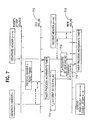
- Fig. 7 is a diagram illustrating an example operation of handoff according to an example of the present invention.
- some information needs to be transferred from an old ANI_AD 710 to a new ANI_AD 712 for handoff. That information is the timer value at the old ANI_AD.
- the old ANI_AD 710 reads (or takes a snapshot of) the current value of the Timer (T_u) at the old ANI_AD and sends it to the new ANI_AD, along with TS0, TS_stride and m_current, block 714 ( Fig. 7 ).
- the new ANI_AD resumes incrementing its timer starting from (T_u). Let T_transfer 715 ( Fig.
- Uplink Transient integral jitter + 2 + 1 ⁇ 2 k Uplink Transient integral jitter (UTIJ) is the uplink transient jitter expressed in units of T msec, rounded to the next higher integer.
- Fig. 7 also illustrates the uplink transient jitter, which includes the bulk delay difference and T_transfer.
- T_transfer is approximately T msec.
- the new ANI_AD 712 due to the asynchronicity of the timer process, almost T msec elapse before timer gets incremented.
- the timer value read when header (n+m) is received is 2, while the real value should be 4.
- there is a skew of -2 As long as condition 3 is met, the skew can be eliminated and the RTP time stamp can be correctly decompressed.
- T_u is transmitted on a high speed signaling network connecting the old and new ANI_AD. Consequently, the time T_transfer should be at most only a small few T msecs. However, the cases where the transfer of T_u is not successful, or not timely enough must be considered. In those cases, the new ANI_AD will notify the term_AD, which sends the full (uncompressed) RTP time stamp until an acknowledgment is received.
- the timer-based compression scheme which uses a compressed time stamp and a local receiver timer may be predicated on the following conditions being met.
- JRF jitter reduction function
- the jitter reduction function calculates the jitter of each packet received over network 108. If the measured packet jitter is greater than 2 k - 2, this is considered excessive jitter and the packet is discarded. Otherwise, the header (or header field) is compressed (as described above) and then transmitted to the receiver terminal (e.g., terminal 130).
- This jitter reduction function (JRF) 115 is an effective technique to limit the jitter on the packets received by the receiver terminal (because the jitter introduced over the RF link may be considered negligible). Moreover, the JRF operates to more efficiently use the available bandwidth over the RF link 140. In the absence of the JRF 115, one or more packets having a jitter greater than 2 k - 2 might be transmitted to the RTP receiver over link 140. However, at the receiver, if the jitter is excessive (i.e., condition 1 is not met), the correct time stamp value cannot be generated, causing the receiver to discard the packet. Thus, JRF merely operates to filter out those packets having excessive jitter that would be discarded at the receiver anyway (avoiding waste of valuable bandwidth over link 140).
- a second example of the present invention provides a timer-based header stripping scheme in which a header or one or more header fields (e.g., including the RTP time stamp) is stripped from the RTP packet prior to transmission across the low bandwidth link (e.g., across RF link 140, Fig. 1 ).
- the time stamp is not explicitly provided in the RTP packet. Rather, timing information can be implicitly provided to the to a header regenerator for incrementing the local timer based upon an essentially constant bit rate channel or a circuit-like connection between the header stripper (e.g., which may exist at an ANI_AD) and the header regenerator (e.g., which may exist at terminal 130).
- Header stripping is based on the idea that for some applications or services, it is not necessary to transport all of the information contained in the IP/UDP/RTP headers, either because they do not change, or because they are not essential to the application/service.
- Basic voice is a typical example.
- the only variable header information that is essential is the RTP time stamp (TS).
- TS RTP time stamp
- SN RTP sequence number
- Header stripping relies on the implicit timing information provided by a circuit-like connection or essentially constant bit rate channel (where no packet jitter is introduced) to allow the RTP time stamp to be regenerated based only on a local timer or counter. This eliminates the need to send the time stamp explicitly (or even send a compressed time stamp).
- compressed SNs can be used in combination with the timing information from the circuit-like channel or connection.
- a circuit-like connection preferably provides a channel having an essentially constant bit rate. When there is no voice sample (e.g. silence interval), the channel may or may not be allocated to other traffic and/or users. Advantages of this header stripping scheme include:
- Fig. 8 is a block diagram illustrating an example stack according to an example embodiment of the present invention.
- a header stripper stack 802 and a header regenerator stack 830 are shown.
- the header stripper stack 802 illustrates some of the components that may be used to strip one or more header fields from the packet, while the header regenerator stack 830 illustrates some of the components that may be used to regenerate the packet header.
- the header stripper stack 802 could be provided, for example, within a type of ANI adapter (e.g., ANI_AD 112, Fig. 1 ), while the header regenerator stack 830 may reside, for example, at a type of terminal adapter (e.g., term_AD 136, Fig. 1 ).
- the header stripper stack 802 includes RTP and UDP layers 804, an IP layer 806.
- the RTP/UDP/IP layers generate an RTP packet 808 (which includes a time stamp in the RTP header).
- the RTP packet 808 is provided to a header stripper (HS) 810 for stripping or removing one or more headers or header fields.
- Layers L1 and L2 812 are provided, where L2 may be a data link layer and layer L1 may be a physical layer, for example. Other layers could be provided as necessary.
- the header regenerator stack 830 includes corresponding layers L 1 and L2 820, a header regenerator (HR) 822 which regenerates the header (including the RTP time stamp) to provide the complete RTP packet 824 (including RTP/UDP/IP headers).
- the packet 824 is provided to IP layer 826 and then to UDP and RTP layers 828.
- the layers L1 and L2 of the header stripper stack 802 and header regenerator stack 830 are in communication across a link 815 or air interface (such as an RF link 140) or across a network. For example, Voice over IP packets are passed through the header stripper 810 before transmission over the link 815 (e.g., wireless link or network).
- the header regenerator 822 regenerates the headers before delivery to the recipient.
- Layers L2/L1 may provide the circuit-like connection, i.e., providing an essentially constant bit rate channel between the header stripper 810 and header regenerator 822.
- layer L 1 may also perform voice payload optimization like uneven bit protection, in addition to optimized channel coding and interleaving. Note that the concept of header stripping is applicable regardless of whether payload optimization is done or not.
- the header stripper (HS) 810 eliminates the jitter in the incoming RTP packets, and plays them back according to the RTP time stamp (TS) in the header.
- eliminating jitter means scheduling the transmission of the voice sample on the circuit-like connection or essentially constant bit rate channel in accordance with the time stamp.
- the packets, after removal or stripping of the headers are transmitted on the circuit-like channel or essentially constant bit rate channel at times based upon their time stamp in the packet. Packets with excessive jitter are discarded, using the jitter reduction function (JRF 115, Fig. 1 ), for example.
- the header regenerator (HR) 822 reconstructs the IP/UDP/RTP fields, which can be classified into the following categories:
- HS header stripper
- an initialization phase is performed to initialize the RTP receiver (i.e., initialize the header regenerator).
- the header stripper keeps sending initialization information (Init_info) until an Ack is received from the receiver.
- Init_info(n) consists essentially of the full IP/UDP/RTP header n (including an initial time stamp and sequence number). The RTP sequence number is used to identify this particular initialization header, since subsequent initialization headers will include larger sequence numbers (assuming the first initialization header is not acked).
- the HR 822 sends an ack(n). Once the header regenerator (HR) 822 has acked a full header, the HS 810 stops sending full headers.
- the HR 822 also starts a local time stamp counter that is initialized to the RTP time stamp received in the Init_info(n).
- the TS counter is similar to the receiver timer in Fig. 1 , but the TS counter is incremented by TS_stride every T msecs (rather than by 1, but it is the same principle as the receiver timer).
- the RTP TS is regenerated from the time stamp (TS) counter.
- the receiver timer (TS timer) has the same frequency as the clock or timer used at the RTP source (i.e., source timer) to generate the time stamp.
- the circuit like connection provides an essentially constant bit rate, and thus, the packet delays are not variable or do not change from packet to packet. As a result, there is no packet jitter due to the essentially constant bit rate channel. Therefore, after the RTP receiver receives the initialization information, including an initial time stamp value (TS0), the RTP receiver can regenerate a correct time stamp for each subsequent packet (after initialization) based only on the time stamp counter (or receiver timer).
- the essentially constant bit rate channel provided between the header stripper 810 and header regenerator 822 need only provide a predetermined number of bits over a predetermined period of time between the header stripper 810 and the header regenerator 822, but this function can performed a variety of different ways.
- the channel can be a constant bit rate channel that is dedicated to the stripper 810 and regenerator 822 or shared among several users.
- the channel can provide, for example one bit every millisecond, or provide 100 bits every 100 milliseconds but where the data rate may not be constant (i.e., may vary) within a 100 ms period.
- the channel may provide the predetermined number of bits through one or more data bursts between the header stripper and header regenerator.
- the channel may provide a chunk or burst of 1000 bits every 10 milliseconds.
- the essentially constant bit rate channel need only provide a predetermined number of bits over a predetermined period of time, but can accomplish this using different techniques.
- RTP SN (as seen by the HS 810) normally increases by 1 from one packet to the next. The only exceptions are when packets are lost or misordered. In the uplink, packet loss or misordering is not expected to happen, since the header stripper (HS) 810 and RTP source are very close to each other. Therefore, the following applies to the downlink.
- the HS 810 does limited buffering to attempt to reorder packets before stripping their headers. Packet with RTP SN n is considered lost if it is still not received by the time packet with RTP SN (n+1) has its header stripped.
- Packet with RTP SN m is misordered if, by the time it is received, packet with RTP SN k has had its header stripped, and k > m.
- the length of the reordering buffer is a design parameter. Too long a buffer will result in an excessively large delay, while too short a buffer will result in too many discarded packets.
- the parameter also depends on the quality provided by the IP network 108 upstream of the HS 810.
- the HR 822 maintains a SN counter which is its best estimate of SN. By observing the Init_info, the HR 822 can obtain the initial SN and the number of bits contained in a packet also known as packet size (p_size).
- the HR 822 initializes the SN counter with the SN in Init_info.
- the HR 822 then "counts" the speech bits received over the essentially constant bit rate channel and increments the SN counter 1 for every p_size bits of speech (it is not incremented when no packet is received, e.g. during a silence interval).
- the HR 822 does not actually count the received bits. Rather, the SN counter at the HR 822 is incremented by 1 every packet duration, where a packet duration is the time required to receive a packet of bits (p_bits).
- the packet duration will be a function of the packet size (p_size) and the bit rate(which is constant over the circuit like connection.
- the HR 822 can generate the time stamps for sequential packets by incrementing the TS counter by TS_stride every T msecs, and by incrementing the SN counter by 1 every packet duration. Therefore, after initialization, these fields can be regenerated at HR 822 with reference only to a local clock (assuming TS_stride and packet duration are known by HR 822).
- the incrementing of SN counter based on time (packet duration) rather than an actual counting of received bits is more robust to errors. In the event one or more bits are dropped before reaching the HR 822, the SN counter will reflect the true value and will not be affected by the lost bits.
- TS and SN can be completely stripped by HS 810 prior to transmission across a link (e.g., RF link 140), and then regenerated by the HR 822 maintaining a local clock or timer (e.g., incrementing TS counter by TS_stride every T msecs and incrementing SN counter by 1 every packet duration).
- a link e.g., RF link 140
- timer e.g., incrementing TS counter by TS_stride every T msecs and incrementing SN counter by 1 every packet duration.
- some of the discontinuity events may include:
- a header string as a sequence of packet headers such that all the packets have the same size (p_size), sequence numbers are consecutive, i.e. n, (n+1), (n+2), etc., and the time stamps(TSs) of consecutive packets are spaced apart by the same increment TS_stride.
- a header string may be considered to be a string of headers having some packet fields in common (e.g., packet size), and other fields which increase linearly across consecutive packets, such as SN and TS.
- a string is usually a talk spurt (e.g., a series of voice samples provided between intervals of silence).
- the transition from one string to another can be caused by any of the discontinuity events, singly or even in combination.
- the HS 810 determines which discontinuity event has occurred, and accordingly sends the needed string initialization (string_init) information to the HR 822.
- Fig. 9 is a table illustrating information which may be provided in messages according to an example embodiment of the invention.
- Init_info typically includes a full header (including full SN and TS), and is sent from the HS 810 to HR 822 (to initialize HR 822) at the beginning of the session.
- HR 822 to initialize HR 822
- HS 810 will continue to resend the init_info until receiving an ack from HR 822, before proceeding with sending of the headerless data packets. Thereafter, there may be one or more strings which can occur, which may require additional updates of fields or values which change from one string to another. These changed values are provided to the HR 822 using string_init.
- String_init includes the p_size value (if it has changed from the previous string), and the TS_stride value (if it has changed from the previous string). If no non-linear shift occurs to the TS from one string to the next, the HR 822 can continue to regenerate the TS based on the TS counter used in the old string. However, if a non-linear shift in the time stamp (TS) occurs between strings (i.e., loss of timing), the updated time stamp must be explicitly sent in the string_init from the HS 810 to the HR 822. The updated TS can be sent as a compressed time stamp 414 (see Fig. 4 ) described above so long as condition 1 is met, as described above. Otherwise, if condition 1 is not met, the full updated time stamp must be transmitted to the HR 822.
- TS time stamp
- ack mode after the HS 810 sends the string_init to the HR 822, the HS 810 may require the HR 822 to acknowledge (or ack) receipt of the updated string information (string_init) before the HS 810 can send the further data packets (headerless packets) to HR 822.
- acknowledge or ack mode the HS 810 repeatedly sends a string_init message to the HR 822 until the HS 810 receives an ack from HR 822 for a string_init message.
- the HS 810 After receiving an ack from the HR 822, the HS 810 will then send the remaining packets of the string as stripped-header packets (since the TS and SN for packets of the new string can now be regenerated using only a local clock or timer).
- the ack requirement (in acknowledged mode) for the string_init message prevents the HS 810 from sending a new string without notifying the HR 822. For example, if the HS 810 sends a new string_init message (e.g., providing updated fields or information related to a discontinuity event) while the link between the HS 810 and HR 822 is temporarily broken, the HS 810 cannot proceed to send header-stripped packets until first receiving the ack from the HR 822.
- speech frames e.g., data packets
- TS and SN are regenerated by using a local clock at the HR 822.
- the HS 810 can determine the events as follows:
- discontinuity events are provided only as examples. Other types of discontinuity events are possible.
- Init_info is normally sent in ack mode, whereby the HS 810 will send Init_info until acked by the HR 822.
- String_init can be sent in ack or unack mode.
- ack mode the HS 810 will send String_init at every packet until acked by the HR 822.
- unack mode the HS 810 will send String_init a certain (predetermined) number of times before sending speech bits only for the remainder of the string.
- the string_init can be repeated at some interval during the string to ensure the HR 822 is synchronized (e.g., has the proper values).
- a compound event which includes the "Size change” or "Stride change” basic event will typically require String_init to be sent in ack mode.
- string_init will carry a generation number.
- the generation number is a counter incremented whenever p_size or TS_stride changes. It is used in the case where p_size or TS_stride change in rapid succession, to keep track of which change has been acked by the HR 822. For example, if p_size changes from value p_size_0 to p_size_1, then again to value p_size_2, the HS 810 will send string_init containing p_size_1, with generation number say 3, then subsequently another string_init containing p_size_2, with generation number 4.
- the unack mode also allows to dispense with a channel to carry acks in stable state, i.e. after call setup and between handovers.
- ANI_AD network adapter
- the handover can be modeled as going through three phases: handover preparation, handover execution and handover completion.
- handover (HO) manager which may be provided in the ANI 110
- handover preparation consists of exchanging signaling messages with the target system to reserve resources in the target system and obtain necessary information on the target cell.
- Handover execution is initiated by the source HO manager sending a HO command to the receiver terminal (or mobile station), along with the information on the target cell.
- the terminal (or mobile station) executes the handover.
- Handover completion involves exchange of signaling between the terminal or mobile station and the target system, notification to the source, and release of resources no longer needed (e.g. at the source).
- the ANI_AD acts as a HR 822 for the uplink data transmission (see uplink 142, Fig. 1 ).
- the target ANI_AD has to be provided with the necessary information to regenerate the full header.
- the main constraints include continuity of RTP TS and RTP SN through handover (HO).
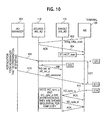
- Fig. 10 is a diagram illustrating a handover process according to an example embodiment of the present invention.
- the terminal130 (or mobile station MS), as an example, may notify the source ANI_AD 112 that the packet size has changed using a string_init message, step 902.
- the source ANI_AD 112 acknowledges this update to the p_size, step 904.
- the terminal 130 moves to a new area covered by the target ANI_AD 114, and the HO manager 901 notifies the source ANI_AD of preparation for a handover (handoff), step 906.
- the source ANI_AD then sends a HO_initialization (HO_init_u) information to the target ANI_AD 114, step 908.
- HO_initialization HO_init_u
- HO_init_u is an estimated view of the full IP/UDP/RTP header.
- TS Timer_u is a counter at the source ANI_AD that was incremented by 1 every T msec.
- HO_init_u includes p_size_u (current size of packet in the uplink direction).
- the target ANI_AD derives the static fields, as well as approximate initial values for changing fields (RTP TS and RTP SN).
- a handover command is sent from the HO manager 901 to the terminal 130 (mobile station), step 910, causing the terminal 130 to switch and now use the target ANI_AD for communication.
- a HO manager may not be necessary as other techniques can be used to initiate a handover.
- a handover is considered as breaking any ongoing string. Therefore, after handover completion, the very first speech sample to be sent is always handled like a new string, which requires sending initialization information (HO_sync_u), step 912.
- ST1 which is the start of HO preparation
- ST2 which is the receipt by MS of HO command
- ST3 which is the time the source ANI_AD took the snapshot of its internal information to be sent in HO_init_u.
- HOT be the time elapsed from ST1 to ST2. From the system design, there is an upper bound on HOT: HOT ⁇ HOT_max.
- a fourth significant point in time is ST4: the first time when the terminal 130 wants to resume sending speech in the target system after HO.
- the terminal 130 determines if the most recent change in p_size_u has been acknowledged by time ST2 - HOT_max. If so, the terminal 130 is certain that HO_init_u contained the up-to-date value of p_size_u. Therefore, there is no need to include it in HO_sync_u. This is because the points in time are ordered as ST1 ⁇ ST3 ⁇ ST2. Otherwise, the terminal 130 (MS) will include the new value of p_size_u in HO_sync_u. The same algorithm applies to TS_stride_u.
- HO_sync_u includes C_SN.
- C_SN is needed because there was a break caused by HO.
- C_TS is needed if the bit rates, packet durations, etc. in the source and target systems are not synchronized. This is likely to be the case.
- HO_sync_u is preferably sent in ack mode.
- HO_init_u and HO_sync_u are used by the target ANI_AD 114 to regenerate the full header as follows. All fields except TS and SN are copied from HO_init_u. SN is obtained by decompressing C_SN in HO_sync_u. TS is determined by decompressing C_TS in HO_sync_u.
- the HS role is transferred from one ANI_AD to another. After handoff, the headers are routed on a new path going through the new ANI_AD instead of the old ANI_AD. As a result, there could be a discontinuity in the timing for the RTP TS regeneration at the terminal 130 (MS).
- HO_init_d consists of p_size_d and TS_stride_d, which are the values last acknowledged by the MS, along with their generation number.
- HO_sync_d consists of C_TS and C_SN.
- HO_sync_d also contains the new value of p_size. If not, HO_sync_d just contains the generation number n of p_size_d. The MS uses the generation number to retrieve the correct p_size. This assumes the MS kept in memory the last few values of p_size, along with their generation number. The same algorithm applies to TS_stride. HO_init_d is sent until acked by the MS_AD. HO_sync_d is sent in ack mode. Handover process is depicted in figure 2 . The case shown is: the most recent change in p_size_u has been acknowledged by time ST2 - HOT_max.
- Each of the above information can be sent in-band or out-of-band.
- the information is sent on the speech channel by stealing the least significant voice bits.
- a dedicated transient channel is set up and torn down when an ack is received.
- a combination of in-band and out-of-band is possible, whereby the out-of-band approach is attempted, but the in-band approach is a fall back solution if there is no resource for a transient channel.
- Acknowledgments can be sent in-band, or out-of-band on their own dedicated ack channel, or out-of-band piggybacked on the other dedicated transient channels (TIC, etc.)
- FIG. 11 is a diagram illustrating an initialization for in-band according to an example embodiment of the invention. If there is continuous voice activity, Init_info sent are Init_info(0), Init_info(R), Init_info (2R), etc. until an ack(n) is received. In Fig. 11 , these init_info messages are shown as init_info 500 and init_info 502. The header stripper acks init_info 500, but not before the HS 810 sends a second init_info packet 502. The next packet 504 is sent from HS 810 to HR 822 as packet payload 504 (without header). The HR 822 then regenerates the SN and TS and other header fields.
- Init_info (0) takes the place of speech samples 0, 1, ..., (R-1), Init_info(R) takes the place of speech samples R, (R+1), ..., (2R-1), and so on. If there is discontinuous voice activity, say header 0 is followed by a L*T msec silence interval, then Init_info(0) is repeated:
- the other information string_init, HO_sync_d, HO_sync_u, Ack), all have a size well below S, so they fit into the space of a speech frame. They steal the least significant voice bits.
- the analysis does not take into account the expansion caused by channel coding, but the concept is valid with or without channel coding. Initialization process for in-band case is shown in figure 3 .
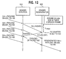
- Fig. 12 is a diagram illustrating an initialization for out-of-band according to an example embodiment of the invention.
- a separate channel is set up with the appropriate bandwidth to carry just the Init_info concurrently with speech, which is carried on a speech channel.
- the separate channel is called the transient initialization channel (TIC).
- TIC transient initialization channel
- the system can attempt to allocate enough bandwidth for the TIC to permit sending a full header once every T msec.
- the TIC is designed to have a fixed timing relationship with the speech channel.
- Acknowledgments can be sent out-of-band by allocating a transient acknowledgment channel (TAC), or sent out-of-band, but piggybacked on a forward transient channel.
- HO_sync_u can be sent out-of-band over a transient uplink handover synchronization channel (TUHOSC).
- TUHOSC transient uplink handover synchronization channel
- TUHOSC is torn down when HO_sync_u is acked.
- TDHOSC transient downlink handover synchronization channel
- HO_init_d is not needed.
- HO_sync_d and HO_sync_u only carry C_SN and C_TS.
- String_init carries C_SN. It carries C_TS only if there is a timing change from one string to the next.
- the terminal (MS) does not have to keep in memory the last few values of p_size and TS_stride. In case of HO, the terminal (MS) does not have to determine whether to include p_size_u in HO_sync_u.
- the only information in the IP/UDP/RTP headers that is essential for basic voice are the static fields and RTP time stamp (TS) and the. RTP sequence number (SN) is also very desirable.
- the scheme described herein achieves transparency for these information fields, and provides an advantageous header overhead compression efficiency. Continuity of all static and non-static fields is maintained through handover. Bandwidth management is also made easier, because in-band as well as out-of-band approaches are possible. Since transparency is maintained for RTP TS and RTP SN, it is even possible to switch back and forth between the header stripping scheme and the header compression scheme described herein that maintains transparency for all the fields. Switching to header compression may be needed when for example, another medium is added to voice.
- the timer and reference based scheme is based on the observations that (1) RTP time stamps when generated at the RTP source are correlated with a linear function of elapsed time between packets, and (2) RTP TS are of the form TS0 + index*TS_stride, where TS0 and TS_stride are constant, and index is an integer (hereinafter index will be referred to as the packed RTP TS). Therefore, in normal operation, the RTP time stamps received at the decompressor are also correlated with continually incrementing timer, with a distortion created only by the cumulative jitter between the source and the decompressor.
- the compressor can calculate an upper bound of the cumulative jitter by adding to the observed network jitter an upper bound of the radio jitter.
- the compressor then just sends as compressed RTP TS the "k" least significant bits of the packed RTP TS.
- the decompressor decompresses RTP TS by first calculating an approximation, and then refining the approximation with the information in the compressed RTP TS to determine the exact value.
- the approximation is obtained by adding to the RTP TS of the previously decompressed header a value proportional to the time elapsed since the previously decompressed header was received.
- the exact value of RTP TS is determined as the one closest to the approximation, whose k least significant bits of the corresponding packed RTP TS match the compressed RTP TS.
- the compressor chooses a value k as the smallest value permitted that would allow the decompressor to decompress correctly, based on the upper bound of the cumulative jitter.
- the receiver uses a timer to obtain an approximation of the RTP TS of the current header (the one to be decompressed), then refines the approximation with the additional information received in the compressed header.
- the compressor sends in the compressed header, k least significant bits of p_TS_current.
- the compressor runs the following algorithm to determine k:
- Network jitter at the compressor can be calculated according three different methods, namely a first method illustrated in Fig. 13 a second method illustrated in Fig. 14 and a third method illustrated in Fig. 15 .
- the second and third methods are described below as Option 1 and Option 2 respectively.
- the first method is adequate for calculating network jitter.
- the preferred methods for calculating network jitter at the compressor are the second and third methods described as Option 1 and Option 2 respectively below.
- network jitter for a particular packet at the compressor is calculated using information with respect to the immediately preceding packet.
- network jitter for packet 2 (j2) is calculated using information with respect to packet 1
- network jitter for packet 3 (j3) is calculated using information with respect to packet 2
- network jitter for packet 4 (j4) is calculated using information with respect to packet 3
- network jitter for packet 5 (j5) is calculated using information with respect to packet 4.
- network jitter for packet 2 equals the calculated jitter j2
- network jitter for packet 3 equal the calculated jitter j3
- network jitter for packet 4 equals the calculated jitter j4
- network jitter for packet 5 equals the calculated jitter j5.
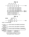
- Fig. 14 The steps used to calculate network jitter for the second method of Option 1 are illustrated in Fig. 14 .
- network jitter for a particular packet is calculated using information with respect to a reference packet.
- packet 2 is the reference packet as illustrated in Fig. 14
- jitter j3 of packet 3 is calculated using information with respect to the reference packet 2
- jitter j4 of packet 4 is calculated using information with respect to the reference packet 2
- jitter j5 of packet 5 is calculated using information with respect to the reference packet 2.
- the network jitter of a current packet is calculated according to the method of Option 1 as follows:
- Fig. 15 The steps used to calculate network jitter for the third method of Option 2 are illustrated in Fig. 15 .
- network jitter at a particular packet is calculated using jitter calculations between the packet of interest and each of a predetermined number of preceding packets.
- the predetermined number of preceding packets is defined as a window and such window can be of any value.
- the window has a value of 4 preceding packets.
- the window could be set at any other value such as, for example, 7 packets. Further, the window could, for example, be set to be a value equal to the number of packets since the last reference packet.
- network jitter for packet 5 is calculated using information with respect to packet 1 j(5, 1), packet 2, j(5, 2), packet 3 j(5, 3) and packet 4, j(5, 4).
- packet 1 j(5, 1)
- packet 2 j(5,2)
- the equations for calculating network jitter according to the third method of Option 2 and a description thereof are set forth below.
- the network jitter of a current packet is calculated according to the method of Option 2 as follows:
- the window W includes headers sent since the last header know to be correctly received (e.g., acknowledged). In the case of no feedback, the window W includes the last L headers sent, where L is a parameter.
- the receiver calculates the time elapsed since the Last_header was received, in units of T msec. That time, Timer (Current_header, Last_header) is added to p_TS_last, to give an approximation of p_TS_current. The receiver then determines the exact value of p_TS_cunrent by choosing the value closest to the approximation, whose k least significant bits match the compressed RTP TS. TS_current is then calculated as TS0 + (p_TS_current)*TS-stride.
- Timer(Current_header, Last_header) can be calculated as (T_current - T_last), where T_current and T_last are the values of R_Timer when Current_header and Last_header were received respectively.
- Max_network_jitter Due to the definition of Max_network_jitter at the compressor: Jitter Current_header Last_header ⁇ J ⁇ 1 ,
- Packet Misordering can be detected by a decreasing RTP sequence number (RTP SN).
- RTP SN RTP sequence number
- the compressor can encode the packed RTP TS using a different scheme, for example, VLE.
- the decompressor is notified of the different encoding by appropriate indicator bits in the compressed header.
- the network jitter is zero (since both the RTP source and the compressor are located in the wireless terminal), and the radio jitter is normally bounded and controlled to remain very small. Therefore, the expected k will be very small and constant, which minimizes the header size fluctuation. This is a very significant advantage for bandwidth management, since for the uplink, the terminal usually has to request for increased bandwidth from the network. Furthermore, there is no packet misordering. Consequently, the timer based scheme is extremely well suited for the uplink.
- the network jitter is not zero, but the overall jitter is normally small to meet the real-time requirements.
- the expected k will still be small and usually constant. There may be more fluctuation in k, but the bandwidth management is less of an issue, since the network controls the bandwidth allocation.
- MS-to-network radio link In cellular systems, there is a MS-to-network radio link and network-to-MS radio link, denoted uplink and downlink respectively.
- MS_AD MS adaptor
- ANI_AD access network infrastructure adaptor
- the specific case of handoff to consider is inter-ANI_AD handoff, where there may be a disruption caused by switching from the old ANI_AD to a new ANI_AD.
- the issue is how to maintain continuity of information through the handoff so that after handoff, the compression/decompression at MS_AD and the new ANI_AD continue without disruption.
- the first method uses the scheme of taking a snapshot of context information exchanged between the ANI_AD and MS_AD, with the handshake method, as disclosed in the related application Serial No. 09/522,497, filed on 09 March 1999 , the same date as the present application for "AN EFFICIENT HANDOFF PROCEDURE FOR HEADER COMPRESSION" by K. Le.
- the context information contains the full RTP TS of a reference header.
- the compressors (MS_AD for uplink and ANI_AD for downlink) temporarily discontinue using the timer-based scheme and send a compressed RTP TS with respect to the reference value.
- VLE encoding as disclosed in the related application Serial No.
- the second method keeps using the timer-based scheme across the handoff.
- the compressor's role is transferred from one ANI-AD to another. After handoff, the headers are routed on a new path going through the new ANI_AD instead of the old ANI_AD.
- the old ANI_AD transfers to the new ANI_AD a snapshot of the following information: T_RFH, p_TS_RFH, current value of S_Timer, TS0, and TS_stride, using the handshake method.
- the snapshot values will be denoted with a star, e.g., T_RFH*).
- the new ANI_AD initializes its S_Timer with the current value of S-timer received from the old ANI_AD and starts incrementing that timer every T msec.
- Initialization of the S_timer with the current S_timer value of the old ANI_AD is a conceptual description. If there is a singe S_timer shared by multiple flows, the actual S_timer is not reinitialized.
- the new ANI_AD sends the k least significant bits of p_TS_current.
- Max_radio_jitter is the maximum jitter on the segment between the new ANI_AD and the MS-AD.
- the receiver calculates the time elapsed since RFH was received, in units of T msec. That time, Timer(Current_header, RFH), is added to p_TS_RFH, to give an approximation of p_TS_current. The receiver then determines the exact value of p_TS_current by choosing the value closet to the approximation, whose k least significant bits match the compressed RTP TS. TS_current is then calculated as TS0 + (p_TS_current)*TS_stride.
- the time elapsed since RFH was received can be calculated as (T_current-T_RFH).
- the new ANI_AD When the context information cannot be transferred to the new ANI_AD in a timely manner, the new ANI_AD will send the ful RTP TS until an acknowledgment is received.
- the decompressor role is transferred from one ANI_AD to another.
- the compressor stays anchored at the MS.
- the old ANI_AD transfers to the new ANI_AD a snapshot of the following information: T_RFH*, p_TS_RFH*, current value of R_Timer*, TS0, and TS_stride, using the handshake method.
- the new ANI_AD initializes its R_Timer with current value of R_Timer received from the old ANI_AD 2 and starts incrementing that timer every T msec.
- Initialization of the R_timer with the current R_timer value of the old ANI_AD is just a conceptual description. If there is a single R_timer shared by multiple flows, the actual R_timer is not reinitialized. Rather, the offset between that R_timer and the value from the old ANI_AD is recorded.
- the new ANI_AD calculates Timer(Current_header, RFH) adds it to p_TS_RFH*, to give an approximation of p-TS-current.
- the receiver determines the exact value to p_TS_current by choosing the value closest to the approximation, whose k least significant bits match the compressed RTP TS.
- TS_current is then calculated as TS0 + (p_TS_current)* TS_stride.
- Timer(Current_header, RFH) can be estimated as (T_current-T_RFH*).
- T_current is the value of R_Timer when Current_header was received.
- Max_radio_jitter is the maximum jitter on the segment between the new ANI_AD and the MS_AD.
- the new ANI_AD When the context information cannot be transferred to the new ANI_AD in a timely manner, the new ANI_AD will notify the MS_AD, which sends the full RTP TS until an acknowledgment is received.
- the cumulative jitter in normal operation is expected to be at most only a few times T msec. Therefore, a value of k around 4 or 5 is sufficient, as a jitter of up to 16 to 32 speech samples can be corrected.
- the size of the compressed header is constant and small.
- the compressor needs to maintain little memory information:
- jitter reduction function can be implemented as a front end to the compressor to filter out packets with excessive jitter (i.e., jitter exceeding some threshold value).
- T_transfer The main difference with respect to the stationary no-handoff case, is the addition of T_transfer.
- the stationary and handoff thresholds may or may not be the same.
- TS_last TS0 + TS+stride* [index_last + adjust (index_last)]
- TS_current TS0 + TS_stride* [index_current) + adjust (index-current].
- the Adjust parameter can be positive or negative.
- the main difference compared to voice is the additional term Adjust.
- the RTP TS is headers coming into the decompressor also follow an adjusted linear pattern as a function of time, but less closely, due to the delay jitter between the source and the decompressor. In normal operation (absence of crashes or failures), the delay jitter is bounded, to meet the requirements of conversational real-time traffic.
- the compressor sends in the compressed header the k least significant bits of p_TS_current.
- the algorithm to determine k is the same as for voice.
- the algorithm to be used is the same as for voice.
Claims (9)
- Un procédé d'émission dans un réseau entre une source et un récepteur d'un champ d'en-tête courant comprenant une empreinte temporelle d'un paquet courant utilisant une technique de compression à base temporisée, comprenant : la délivrance depuis un compresseur vers un décompresseur d'une valeur d'empreinte temporelle initiale d'un champ d'en-tête ; le calcul dans le compresseur d'un champ d'en-tête comprimé du paquet courant en fonction du champ d'en-tête courant du paquet courant et de la gigue, où ladite étape de calcul comprend les étapes suivantes : le calcul d'un effet de gigue que le réseau introduit entre une source et ledit décompresseur sur l'émission des paquets, et le calcul du champ d'en-tête comprimé en tant que partie d'une valeur d'empreinte temporelle, ladite partie étant une fonction de la gigue ; la réception du champ d'en-tête comprimé du paquet courant dans le décompresseur ; l'estimation du champ d'en-tête du paquet courant en fonction du temps écoulé dans le décompresseur entre la réception du champ d'en-tête comprimé du paquet courant et la réception d'un champ d'en-tête d'un paquet précédent qui a été décomprimé et une valeur d'empreinte temporelle décomprimée du paquet précédent ; et la correction du champ d'en-tête courant estimé en fonction du champ d'en-tête comprimé reçu par le décompresseur.
- Un procédé selon la revendication 1, dans lequel ledit calcul de l'effet de gigue comprend les étapes suivantes : calcul d'un effet de gigue sur le réseau avant le compresseur ; et calcul d'un effet de gigue sur le réseau entre le compresseur et le décompresseur.
- Un procédé selon la revendication 2, dans lequel ledit effet de gigue sur le réseau entre le compresseur et le décompresseur est établi à une valeur de borne supérieure pour la gigue.
- Un procédé selon la revendication 2, dans lequel ledit calcul d'un effet de gigue sur le réseau avant le compresseur comprend : le calcul de l'effet de gigue sur un paquet courant en utilisant des informations par rapport à un paquet de référence.
- Un procédé selon la revendication 2, dans lequel ledit calcul d'un effet de gigue sur le réseau avant le compresseur comprend : le calcul de l'effet de gigue sur un paquet courant en utilisant des informations par rapport audit paquet courant et à chacun d'un nombre prédéterminé de paquets précédents.
- Un procédé selon la revendication 2, dans lequel ledit calcul d'un effet de gigue sur le réseau avant le compresseur comprend : le calcul de l'effet de gigue sur un paquet courant en utilisant des informations par rapport audit paquet courant et à chaque parquet précédent jusqu'à un paquet de référence.
- Un procédé selon la revendication 1, dans lequel ledit calcul dans le compresseur du champ d'en-tête comprimé du paquet courant comprend : le calcul du champ d'en-tête comprimé du paquet courant en tant que k bits les moins significatifs de la valeur de l'empreinte temporelle, k étant un entier.
- Un procédé selon la revendication 1, dans lequel ledit champ d'en-tête comprend une empreinte temporelle RTP.
- Un procédé selon la revendication 1, dans lequel ledit calcul dans le compresseur du champ d'en-tête comprimé du paquet courant comprend : la conversion de la valeur d'empreinte temporelle en une autre valeur, appelée valeur de paquet, qui nécessite moins de bits pour sa représentation, et le calcul du champ d'en-tête comprimé du paquet courant en tant que k bits les moins significatifs de la valeur du paquet, k étant un entier.
Priority Applications (5)
| Application Number | Priority Date | Filing Date | Title |
|---|---|---|---|
| EP10150230A EP2169906B1 (fr) | 2000-03-09 | 2001-03-09 | Technique de compression d'un champ d'en-tête dans un paquet de données |
| EP10150243A EP2169996B1 (fr) | 2000-03-09 | 2001-03-09 | Technique de compression d'un champ d'en-tête dans un paquet de données |
| DK10150230.0T DK2169906T3 (da) | 2000-03-09 | 2001-03-09 | Fremgangsmåde til komprimering af et headerfelt i en datapakke |
| EP10150242A EP2169907B1 (fr) | 2000-03-09 | 2001-03-09 | Technique de compression d'un champ d'en-tête dans un paquet de données |
| EP12165329.9A EP2490398B1 (fr) | 2000-03-09 | 2001-03-09 | Technique de compression d'un champ d'en-tête dans un paquet de données |
Applications Claiming Priority (3)
| Application Number | Priority Date | Filing Date | Title |
|---|---|---|---|
| US522363 | 1990-05-08 | ||
| US09/522,363 US6680955B1 (en) | 1999-08-20 | 2000-03-09 | Technique for compressing a header field in a data packet |
| PCT/US2001/007573 WO2001067709A2 (fr) | 2000-03-09 | 2001-03-09 | Technique de compression d'un champ d'en-tete dans un paquet de donnees |
Related Child Applications (4)
| Application Number | Title | Priority Date | Filing Date |
|---|---|---|---|
| EP12165329.9A Division EP2490398B1 (fr) | 2000-03-09 | 2001-03-09 | Technique de compression d'un champ d'en-tête dans un paquet de données |
| EP10150242.5 Division-Into | 2010-01-07 | ||
| EP10150243.3 Division-Into | 2010-01-07 | ||
| EP10150230.0 Division-Into | 2010-01-07 |
Publications (2)
| Publication Number | Publication Date |
|---|---|
| EP1262052A2 EP1262052A2 (fr) | 2002-12-04 |
| EP1262052B1 true EP1262052B1 (fr) | 2010-03-03 |
Family
ID=24080562
Family Applications (5)
| Application Number | Title | Priority Date | Filing Date |
|---|---|---|---|
| EP10150243A Expired - Lifetime EP2169996B1 (fr) | 2000-03-09 | 2001-03-09 | Technique de compression d'un champ d'en-tête dans un paquet de données |
| EP12165329.9A Expired - Lifetime EP2490398B1 (fr) | 2000-03-09 | 2001-03-09 | Technique de compression d'un champ d'en-tête dans un paquet de données |
| EP10150242A Expired - Lifetime EP2169907B1 (fr) | 2000-03-09 | 2001-03-09 | Technique de compression d'un champ d'en-tête dans un paquet de données |
| EP10150230A Expired - Lifetime EP2169906B1 (fr) | 2000-03-09 | 2001-03-09 | Technique de compression d'un champ d'en-tête dans un paquet de données |
| EP01916516A Expired - Lifetime EP1262052B1 (fr) | 2000-03-09 | 2001-03-09 | Technique de compression d'un champ d'en-tete dans un paquet de donnees |
Family Applications Before (4)
| Application Number | Title | Priority Date | Filing Date |
|---|---|---|---|
| EP10150243A Expired - Lifetime EP2169996B1 (fr) | 2000-03-09 | 2001-03-09 | Technique de compression d'un champ d'en-tête dans un paquet de données |
| EP12165329.9A Expired - Lifetime EP2490398B1 (fr) | 2000-03-09 | 2001-03-09 | Technique de compression d'un champ d'en-tête dans un paquet de données |
| EP10150242A Expired - Lifetime EP2169907B1 (fr) | 2000-03-09 | 2001-03-09 | Technique de compression d'un champ d'en-tête dans un paquet de données |
| EP10150230A Expired - Lifetime EP2169906B1 (fr) | 2000-03-09 | 2001-03-09 | Technique de compression d'un champ d'en-tête dans un paquet de données |
Country Status (16)
| Country | Link |
|---|---|
| US (1) | US6680955B1 (fr) |
| EP (5) | EP2169996B1 (fr) |
| JP (2) | JP4159287B2 (fr) |
| KR (1) | KR100502313B1 (fr) |
| CN (2) | CN1185844C (fr) |
| AT (3) | ATE460038T1 (fr) |
| AU (2) | AU4353301A (fr) |
| BR (1) | BRPI0109097B1 (fr) |
| CA (1) | CA2402438C (fr) |
| DE (1) | DE60141453D1 (fr) |
| DK (2) | DK2169906T3 (fr) |
| ES (3) | ES2460140T3 (fr) |
| MX (1) | MXPA02008806A (fr) |
| PT (2) | PT2169906E (fr) |
| RU (1) | RU2278478C2 (fr) |
| WO (1) | WO2001067709A2 (fr) |
Families Citing this family (79)
| Publication number | Priority date | Publication date | Assignee | Title |
|---|---|---|---|---|
| KR100612003B1 (ko) * | 2000-02-26 | 2006-08-11 | 삼성전자주식회사 | 통신망에서 비트 스트림 송수신 장치 및 그 방법 |
| US7061936B2 (en) * | 2000-03-03 | 2006-06-13 | Ntt Docomo, Inc. | Method and apparatus for packet transmission with header compression |
| US7136377B1 (en) * | 2000-03-31 | 2006-11-14 | Cisco Technology, Inc. | Tunneled datagram switching |
| US7512069B2 (en) * | 2000-05-18 | 2009-03-31 | Exfo Service Assurance, Inc. | IP packet identification method and system for TCP connection and UDP stream |
| AU2001259867A1 (en) * | 2000-05-18 | 2001-11-26 | Brix Networks, Inc. | Hardware time stamping and registration of packetized data method and system |
| US7788211B2 (en) * | 2000-06-16 | 2010-08-31 | Nokia Networks Oy | Robust and efficient compression of list of items |
| JP4520032B2 (ja) * | 2000-08-17 | 2010-08-04 | パナソニック株式会社 | ヘッダ圧縮装置およびヘッダ圧縮方法 |
| DE60018927T2 (de) * | 2000-09-07 | 2005-07-28 | Matsushita Electric Industrial Co. Ltd., Kadoma | Verfahren und Vorrichtung zur Datenpaketenübertragung |
| AU2001294142A1 (en) * | 2000-09-20 | 2002-04-02 | Main.Net Communication Ltd. | Multimedia communications over power lines |
| ATE330425T1 (de) * | 2000-09-28 | 2006-07-15 | Nokia Corp | Verfahren und kompressor zur komprimierung von zeitstempelinformation von paketen |
| EP1340351B1 (fr) * | 2000-10-11 | 2007-12-12 | Broadcom Corporation | Codage delta dynamique pour suppression d'en-tete dans des modems cables |
| US20020089602A1 (en) * | 2000-10-18 | 2002-07-11 | Sullivan Gary J. | Compressed timing indicators for media samples |
| JP2002152308A (ja) * | 2000-11-09 | 2002-05-24 | Nec Corp | データ通信システム、その通信方法及びその通信プログラムを記録した記録媒体 |
| US6963587B2 (en) * | 2000-11-16 | 2005-11-08 | Telefonaktiebolaget Lm Ericsson (Publ) | Communication system and method utilizing request-reply communication patterns for data compression |
| US6950445B2 (en) * | 2000-11-16 | 2005-09-27 | Telefonaktiebolaget Lm Ericsson (Publ) | Communication system and method for shared context compression |
| US7136395B2 (en) * | 2000-11-30 | 2006-11-14 | Telefonaktiebolaget L M Ericsson (Publ) | Method and system for transmission of headerless data packets over a wireless link |
| JP4483100B2 (ja) * | 2001-02-20 | 2010-06-16 | 株式会社日立製作所 | ネットワーク間接続装置 |
| WO2002080604A1 (fr) * | 2001-03-28 | 2002-10-10 | Nokia Corporation | Procede pour delivrer des parametres pendant un changement d'acces, systeme de communication cellulaire, equipement utilisateur et element de reseau |
| EP1384385A1 (fr) * | 2001-05-04 | 2004-01-28 | Nokia Corporation | Transmission de parametres pendant un changement d'acces, systeme de communication cellulaire, appareil utilisateur et element de reseau |
| JP3569241B2 (ja) * | 2001-05-29 | 2004-09-22 | 松下電器産業株式会社 | パケット受信装置及びパケット受信方法 |
| JP3617967B2 (ja) * | 2001-09-28 | 2005-02-09 | 松下電器産業株式会社 | ヘッダ圧縮パケット受信装置及び方法 |
| EP1315356B1 (fr) | 2001-11-24 | 2008-10-22 | Lg Electronics Inc. | Procédé de transmission de données en paquet en forme comprimé dans une système de communication |
| US7359337B2 (en) | 2001-12-18 | 2008-04-15 | Mitsubishi Denki Kabushiki Kaisha | Communication system, transmission terminal and receiving terminal therefor |
| FI113324B (fi) * | 2001-12-21 | 2004-03-31 | Nokia Corp | Parannettu laitejärjestely, päätelaite ja menetelmä audiosignaalin siirrossa pakettikytkentäisessä tiedonsiirtoverkossa |
| EP1349285A1 (fr) * | 2002-03-28 | 2003-10-01 | Matsushita Electric Industrial Co., Ltd. | Méthode pour l'usage efficace des bits attribués au numéro de séquence pour la transmission des données d'en-tête de trame comprimées |
| US7170870B2 (en) * | 2002-05-07 | 2007-01-30 | Microsoft Corporation | Data packet transmission for channel-sharing collocated wireless devices |
| KR100497357B1 (ko) * | 2002-06-26 | 2005-06-23 | 삼성전자주식회사 | 인터넷 프로토콜 기반 네트워크 환경에 있어서 헤더 압축및 패킷 다중화 장치와 그 방법 |
| CN1304972C (zh) * | 2002-06-26 | 2007-03-14 | 威盛电子股份有限公司 | 数据封包转移方法 |
| JP4317403B2 (ja) * | 2002-08-09 | 2009-08-19 | パナソニック株式会社 | ヘッダ圧縮装置及びヘッダ圧縮方法 |
| US7454494B1 (en) | 2003-01-07 | 2008-11-18 | Exfo Service Assurance Inc. | Apparatus and method for actively analyzing a data packet delivery path |
| US20040136476A1 (en) * | 2003-01-10 | 2004-07-15 | Rosen Eric C. | Method and apparatus for compressing header information for short data burst messaging |
| US7489362B2 (en) * | 2003-03-04 | 2009-02-10 | Broadcom Corporation | Television functionality on a chip |
| FR2857538B1 (fr) * | 2003-07-08 | 2006-10-06 | At & T Corp | Systeme et methode de compression d'en-tete de paquets bases sur la creation dynamique d'un gabarit |
| US7065087B2 (en) * | 2003-07-08 | 2006-06-20 | Cisco Technology, Inc. | Performing compression of user datagram protocol packets |
| US7317724B2 (en) * | 2003-07-08 | 2008-01-08 | Cisco Technology, Inc. | Performing compression of user datagram protocol packets |
| US7461282B2 (en) * | 2003-08-15 | 2008-12-02 | Broadcom Corporation | System and method for generating multiple independent, synchronized local timestamps |
| US7512715B2 (en) * | 2003-09-26 | 2009-03-31 | Nokia Corporation | System and method for requesting a resource over at least one network with reduced overhead |
| CN100505729C (zh) * | 2003-10-30 | 2009-06-24 | Ut斯达康(中国)有限公司 | 采用头压缩技术的实时ip分组的无线传输装置和方法 |
| US7626975B2 (en) * | 2003-11-05 | 2009-12-01 | Telefonaktiebolaget Lm Ercisson (Publ) | Method of synchronizing broadcast streams in multiple soft handoff sectors |
| US7430617B2 (en) * | 2003-12-19 | 2008-09-30 | Nokia Corporation | Method and system for header compression |
| US7974191B2 (en) * | 2004-03-10 | 2011-07-05 | Alcatel-Lucent Usa Inc. | Method, apparatus and system for the synchronized combining of packet data |
| MXPA06013193A (es) | 2004-05-13 | 2007-02-14 | Qualcomm Inc | Compresion de encabezado de datos de multimedia transmitidos sobre un sistema de comunicacion inalambrica. |
| EP1603339A1 (fr) * | 2004-06-01 | 2005-12-07 | STMicroelectronics S.r.l. | Méthode et système de communication de données vidéos dans un réseau de paquets commutés, réseau et programme d'ordinateur associés |
| US8165104B2 (en) * | 2004-12-08 | 2012-04-24 | Qualcomm Incorporated | Methods and systems for enhancing local repair in robust header compression |
| US8009699B2 (en) * | 2005-07-12 | 2011-08-30 | Qualcomm Incorporated | Efficient encoding of out of order data packets in a network |
| US9031071B2 (en) * | 2005-08-26 | 2015-05-12 | Alcatel Lucent | Header elimination for real time internet applications |
| KR100748342B1 (ko) | 2005-09-14 | 2007-08-09 | 매그나칩 반도체 유한회사 | 씨모스 이미지 센서의 제조방법 |
| US7764713B2 (en) * | 2005-09-28 | 2010-07-27 | Avaya Inc. | Synchronization watermarking in multimedia streams |
| US7907600B2 (en) * | 2005-12-23 | 2011-03-15 | Qualcomm Incorporated | System and method for optimizing robust header compression (ROHC) in high delay variance environment |
| US7907609B2 (en) * | 2006-01-06 | 2011-03-15 | Qualcomm, Incorporated | Method and apparatus for enhancing RoHC performance when encountering silence suppression |
| JP4640824B2 (ja) * | 2006-01-30 | 2011-03-02 | 富士通株式会社 | 通信環境の測定方法、受信装置、及びコンピュータプログラム |
| US8046731B2 (en) * | 2006-04-28 | 2011-10-25 | Sap Ag | Timer service computer program components |
| EP1863232A1 (fr) * | 2006-05-29 | 2007-12-05 | Stmicroelectronics Sa | Distributeur de largeur de bande sur puce |
| CN101102263B (zh) * | 2006-07-07 | 2010-05-12 | 华为技术有限公司 | 压缩报文恢复方法及装置 |
| US10075182B2 (en) * | 2006-10-13 | 2018-09-11 | Qualcomm Incorporated | Message compression |
| CN101170487B (zh) * | 2006-10-25 | 2010-05-12 | 华为技术有限公司 | 数据流复用中的压缩方法和压缩系统以及压缩设备 |
| WO2008051123A1 (fr) * | 2006-10-27 | 2008-05-02 | Telefonaktiebolaget Lm Ericsson (Publ) | Procédé de récupération d'horloge utilisant des estampilles temporelles mises à jour |
| US8027328B2 (en) * | 2006-12-26 | 2011-09-27 | Alcatel Lucent | Header compression in a wireless communication network |
| US7899025B2 (en) * | 2006-12-26 | 2011-03-01 | Alcatel-Lucent Usa Inc. | Header suppression in a wireless communication network |
| NZ578058A (en) * | 2007-03-16 | 2012-06-29 | Ericsson Telefon Ab L M | Method and apparatus for relocating a header compression context in a wireless communication system |
| US8537742B2 (en) * | 2007-03-17 | 2013-09-17 | Qualcomm Incorporated | Reverse-link quality-of-service information in data packet header |
| CN101193062B (zh) * | 2007-07-25 | 2011-07-13 | 中兴通讯股份有限公司 | 一种rohc压缩中ts值还原方法 |
| US20090052453A1 (en) * | 2007-08-22 | 2009-02-26 | Minkyu Lee | Method and apparatus for improving the performance of voice over IP (VoIP) speech communications systems which use robust header compression (RoHC) techniques |
| DE602007008435D1 (de) * | 2007-10-22 | 2010-09-23 | Alcatel Lucent | Synchronisation für Multicast- und Rundfunkdienste in einem drahtlosen Kommunikationssystem |
| US8548002B2 (en) * | 2008-02-08 | 2013-10-01 | Koolspan, Inc. | Systems and methods for adaptive multi-rate protocol enhancement |
| US8184529B2 (en) * | 2008-10-17 | 2012-05-22 | Brother Kogyo Kabushiki Kaisha | Communication apparatus, method, and program for transmitting and receiving packet data |
| RU2568778C2 (ru) * | 2010-11-02 | 2015-11-20 | Ай-Сес (Инновэйтив Компрешн Инджиниринг Солюшнз) | Способ сжатия цифровых значений изображения, аудио и/или видео файлов |
| US9515925B2 (en) | 2011-05-19 | 2016-12-06 | Qualcomm Incorporated | Apparatus and methods for media access control header compression |
| US9125181B2 (en) * | 2011-08-23 | 2015-09-01 | Qualcomm Incorporated | Systems and methods for compressing headers |
| US20140153580A1 (en) * | 2013-02-15 | 2014-06-05 | Comtech Ef Data Corp. | Reference encoding and decoding for improving network header compression throughput for noisy channels |
| EP3075132B1 (fr) | 2013-11-27 | 2021-08-18 | Telefonaktiebolaget LM Ericsson (publ) | Format de charge utile rtp hybride |
| US11245595B2 (en) * | 2014-03-12 | 2022-02-08 | Sensia Llc | Management of user interfaces within a network |
| WO2016144223A1 (fr) * | 2015-03-11 | 2016-09-15 | Telefonaktiebolaget Lm Ericsson (Publ) | Contrôle de flux de données multipoint |
| CN106941697A (zh) * | 2016-01-04 | 2017-07-11 | 中兴通讯股份有限公司 | 一种发送、接收时间戳信息的方法和装置 |
| US10498683B2 (en) * | 2016-07-20 | 2019-12-03 | At&T Intellectual Property I, L.P. | Compressed message sets for storage efficiency |
| CN107707565B (zh) * | 2017-11-07 | 2020-05-19 | 盛科网络(苏州)有限公司 | 一种udf报文解析芯片 |
| US11082544B2 (en) * | 2018-03-09 | 2021-08-03 | Microchip Technology Incorporated | Compact timestamp, encoders and decoders that implement the same, and related devices, systems and methods |
| US10701124B1 (en) | 2018-12-11 | 2020-06-30 | Microsoft Technology Licensing, Llc | Handling timestamp inaccuracies for streaming network protocols |
| US11943125B2 (en) * | 2022-01-26 | 2024-03-26 | Dish Network Technologies India Private Limited | Discontinuity detection in transport streams |
Family Cites Families (10)
| Publication number | Priority date | Publication date | Assignee | Title |
|---|---|---|---|---|
| US6122759A (en) * | 1995-10-10 | 2000-09-19 | Lucent Technologies Inc. | Method and apparatus for restoration of an ATM network |
| US6011590A (en) * | 1997-01-03 | 2000-01-04 | Ncr Corporation | Method of transmitting compressed information to minimize buffer space |
| JPH11163947A (ja) * | 1997-09-22 | 1999-06-18 | Toshiba Corp | ゲートウェイ装置、無線端末装置、ルータ装置および通信ネットワークのゲートウェイ制御方法 |
| US6498791B2 (en) * | 1998-04-03 | 2002-12-24 | Vertical Networks, Inc. | Systems and methods for multiple mode voice and data communications using intelligently bridged TDM and packet buses and methods for performing telephony and data functions using the same |
| US6611519B1 (en) * | 1998-08-19 | 2003-08-26 | Swxtch The Rules, Llc | Layer one switching in a packet, cell, or frame-based network |
| US6535505B1 (en) * | 1998-09-30 | 2003-03-18 | Cisco Technology, Inc. | Method and apparatus for providing a time-division multiplexing (TDM) interface among a high-speed data stream and multiple processors |
| US6549587B1 (en) * | 1999-09-20 | 2003-04-15 | Broadcom Corporation | Voice and data exchange over a packet based network with timing recovery |
| US6404746B1 (en) * | 1999-07-13 | 2002-06-11 | Intervoice Limited Partnership | System and method for packet network media redirection |
| US6542931B1 (en) * | 1999-11-05 | 2003-04-01 | Nokia Corporation | Using sparse feedback to increase bandwidth efficiency in high delay, low bandwidth environment |
| US6300887B1 (en) * | 1999-11-09 | 2001-10-09 | Nokia Networks Oy | Efficient handoff procedure for header compression |
-
2000
- 2000-03-09 US US09/522,363 patent/US6680955B1/en not_active Expired - Lifetime
-
2001
- 2001-03-09 RU RU2002126997/09A patent/RU2278478C2/ru active
- 2001-03-09 DK DK10150230.0T patent/DK2169906T3/da active
- 2001-03-09 MX MXPA02008806A patent/MXPA02008806A/es active IP Right Grant
- 2001-03-09 DE DE60141453T patent/DE60141453D1/de not_active Expired - Lifetime
- 2001-03-09 AT AT01916516T patent/ATE460038T1/de not_active IP Right Cessation
- 2001-03-09 ES ES12165329.9T patent/ES2460140T3/es not_active Expired - Lifetime
- 2001-03-09 DK DK12165329.9T patent/DK2490398T3/da active
- 2001-03-09 PT PT101502300T patent/PT2169906E/pt unknown
- 2001-03-09 AU AU4353301A patent/AU4353301A/xx active Pending
- 2001-03-09 EP EP10150243A patent/EP2169996B1/fr not_active Expired - Lifetime
- 2001-03-09 PT PT121653299T patent/PT2490398E/pt unknown
- 2001-03-09 AU AU2001243533A patent/AU2001243533B2/en not_active Expired
- 2001-03-09 BR BRPI0109097-6A patent/BRPI0109097B1/pt active IP Right Grant
- 2001-03-09 EP EP12165329.9A patent/EP2490398B1/fr not_active Expired - Lifetime
- 2001-03-09 EP EP10150242A patent/EP2169907B1/fr not_active Expired - Lifetime
- 2001-03-09 ES ES01916516T patent/ES2339742T3/es not_active Expired - Lifetime
- 2001-03-09 AT AT10150243T patent/ATE547885T1/de active
- 2001-03-09 KR KR10-2002-7011788A patent/KR100502313B1/ko active IP Right Grant
- 2001-03-09 EP EP10150230A patent/EP2169906B1/fr not_active Expired - Lifetime
- 2001-03-09 CN CNB018061737A patent/CN1185844C/zh not_active Expired - Lifetime
- 2001-03-09 CA CA002402438A patent/CA2402438C/fr not_active Expired - Lifetime
- 2001-03-09 WO PCT/US2001/007573 patent/WO2001067709A2/fr active IP Right Grant
- 2001-03-09 CN CN2004100974838A patent/CN1617540B/zh not_active Expired - Lifetime
- 2001-03-09 EP EP01916516A patent/EP1262052B1/fr not_active Expired - Lifetime
- 2001-03-09 AT AT10150242T patent/ATE543320T1/de active
- 2001-03-09 JP JP2001565612A patent/JP4159287B2/ja not_active Expired - Lifetime
- 2001-03-09 ES ES10150230T patent/ES2399020T3/es not_active Expired - Lifetime
-
2007
- 2007-09-12 JP JP2007236622A patent/JP4612028B2/ja not_active Expired - Lifetime
Also Published As
Similar Documents
| Publication | Publication Date | Title |
|---|---|---|
| EP1262052B1 (fr) | Technique de compression d'un champ d'en-tete dans un paquet de donnees | |
| AU2001243533A1 (en) | A technique for compressing a header field in a data packet | |
| JP3940159B2 (ja) | ヘッダ圧縮のための効率的ハンド・オフ処理手順 | |
| US6788675B1 (en) | Method and apparatus for telecommunications using internet protocol | |
| EP1221239B1 (fr) | Procede et systeme de transmission et de reception de paquets | |
| EP1926282B1 (fr) | Système et procédé pour la transmission et la réception de paquets |
Legal Events
| Date | Code | Title | Description |
|---|---|---|---|
| PUAI | Public reference made under article 153(3) epc to a published international application that has entered the european phase |
Free format text: ORIGINAL CODE: 0009012 |
|
| 17P | Request for examination filed |
Effective date: 20020812 |
|
| AK | Designated contracting states |
Kind code of ref document: A2 Designated state(s): AT BE CH CY DE DK ES FI FR GB GR IE IT LI LU MC NL PT SE TR |
|
| AX | Request for extension of the european patent |
Free format text: AL;LT;LV;MK;RO;SI |
|
| 17Q | First examination report despatched |
Effective date: 20090202 |
|
| RAP1 | Party data changed (applicant data changed or rights of an application transferred) |
Owner name: LE, KHIEM Owner name: QUALCOMM INCORPORATED |
|
| RAP1 | Party data changed (applicant data changed or rights of an application transferred) |
Owner name: QUALCOMM INCORPORATED |
|
| GRAP | Despatch of communication of intention to grant a patent |
Free format text: ORIGINAL CODE: EPIDOSNIGR1 |
|
| GRAS | Grant fee paid |
Free format text: ORIGINAL CODE: EPIDOSNIGR3 |
|
| GRAA | (expected) grant |
Free format text: ORIGINAL CODE: 0009210 |
|
| AK | Designated contracting states |
Kind code of ref document: B1 Designated state(s): AT BE CH CY DE DK ES FI FR GB GR IE IT LI LU MC NL PT SE TR |
|
| REG | Reference to a national code |
Ref country code: GB Ref legal event code: FG4D |
|
| REG | Reference to a national code |
Ref country code: CH Ref legal event code: EP |
|
| REG | Reference to a national code |
Ref country code: IE Ref legal event code: FG4D |
|
| REF | Corresponds to: |
Ref document number: 60141453 Country of ref document: DE Date of ref document: 20100415 Kind code of ref document: P |
|
| REG | Reference to a national code |
Ref country code: ES Ref legal event code: FG2A Ref document number: 2339742 Country of ref document: ES Kind code of ref document: T3 |
|
| REG | Reference to a national code |
Ref country code: NL Ref legal event code: T3 |
|
| REG | Reference to a national code |
Ref country code: SE Ref legal event code: TRGR |
|
| PG25 | Lapsed in a contracting state [announced via postgrant information from national office to epo] |
Ref country code: AT Free format text: LAPSE BECAUSE OF FAILURE TO SUBMIT A TRANSLATION OF THE DESCRIPTION OR TO PAY THE FEE WITHIN THE PRESCRIBED TIME-LIMIT Effective date: 20100303 |
|
| PG25 | Lapsed in a contracting state [announced via postgrant information from national office to epo] |
Ref country code: MC Free format text: LAPSE BECAUSE OF NON-PAYMENT OF DUE FEES Effective date: 20100331 Ref country code: CY Free format text: LAPSE BECAUSE OF FAILURE TO SUBMIT A TRANSLATION OF THE DESCRIPTION OR TO PAY THE FEE WITHIN THE PRESCRIBED TIME-LIMIT Effective date: 20100303 Ref country code: GR Free format text: LAPSE BECAUSE OF FAILURE TO SUBMIT A TRANSLATION OF THE DESCRIPTION OR TO PAY THE FEE WITHIN THE PRESCRIBED TIME-LIMIT Effective date: 20100604 |
|
| REG | Reference to a national code |
Ref country code: CH Ref legal event code: PL |
|
| PLBE | No opposition filed within time limit |
Free format text: ORIGINAL CODE: 0009261 |
|
| STAA | Information on the status of an ep patent application or granted ep patent |
Free format text: STATUS: NO OPPOSITION FILED WITHIN TIME LIMIT |
|
| PG25 | Lapsed in a contracting state [announced via postgrant information from national office to epo] |
Ref country code: DK Free format text: LAPSE BECAUSE OF FAILURE TO SUBMIT A TRANSLATION OF THE DESCRIPTION OR TO PAY THE FEE WITHIN THE PRESCRIBED TIME-LIMIT Effective date: 20100303 Ref country code: PT Free format text: LAPSE BECAUSE OF FAILURE TO SUBMIT A TRANSLATION OF THE DESCRIPTION OR TO PAY THE FEE WITHIN THE PRESCRIBED TIME-LIMIT Effective date: 20100705 |
|
| 26N | No opposition filed |
Effective date: 20101206 |
|
| PG25 | Lapsed in a contracting state [announced via postgrant information from national office to epo] |
Ref country code: LI Free format text: LAPSE BECAUSE OF NON-PAYMENT OF DUE FEES Effective date: 20100331 Ref country code: CH Free format text: LAPSE BECAUSE OF NON-PAYMENT OF DUE FEES Effective date: 20100331 |
|
| PG25 | Lapsed in a contracting state [announced via postgrant information from national office to epo] |
Ref country code: LU Free format text: LAPSE BECAUSE OF NON-PAYMENT OF DUE FEES Effective date: 20100309 |
|
| PG25 | Lapsed in a contracting state [announced via postgrant information from national office to epo] |
Ref country code: TR Free format text: LAPSE BECAUSE OF FAILURE TO SUBMIT A TRANSLATION OF THE DESCRIPTION OR TO PAY THE FEE WITHIN THE PRESCRIBED TIME-LIMIT Effective date: 20100303 |
|
| REG | Reference to a national code |
Ref country code: FR Ref legal event code: PLFP Year of fee payment: 16 |
|
| REG | Reference to a national code |
Ref country code: FR Ref legal event code: PLFP Year of fee payment: 17 |
|
| REG | Reference to a national code |
Ref country code: FR Ref legal event code: PLFP Year of fee payment: 18 |
|
| REG | Reference to a national code |
Ref country code: DE Ref legal event code: R082 Ref document number: 60141453 Country of ref document: DE Representative=s name: BARDEHLE PAGENBERG PARTNERSCHAFT MBB PATENTANW, DE Ref country code: DE Ref legal event code: R081 Ref document number: 60141453 Country of ref document: DE Owner name: QUALCOMM INCORPORATED, SAN DIEGO, US Free format text: FORMER OWNER: QUALCOMM INC., SAN DIEGO, CALIF., US |
|
| REG | Reference to a national code |
Ref country code: FR Ref legal event code: PLFP Year of fee payment: 20 |
|
| PGFP | Annual fee paid to national office [announced via postgrant information from national office to epo] |
Ref country code: DE Payment date: 20200214 Year of fee payment: 20 Ref country code: FI Payment date: 20200225 Year of fee payment: 20 Ref country code: IE Payment date: 20200225 Year of fee payment: 20 Ref country code: GB Payment date: 20200228 Year of fee payment: 20 Ref country code: NL Payment date: 20200227 Year of fee payment: 20 Ref country code: IT Payment date: 20200316 Year of fee payment: 20 Ref country code: SE Payment date: 20200309 Year of fee payment: 20 |
|
| PGFP | Annual fee paid to national office [announced via postgrant information from national office to epo] |
Ref country code: BE Payment date: 20200218 Year of fee payment: 20 |
|
| PGFP | Annual fee paid to national office [announced via postgrant information from national office to epo] |
Ref country code: FR Payment date: 20200219 Year of fee payment: 20 |
|
| PGFP | Annual fee paid to national office [announced via postgrant information from national office to epo] |
Ref country code: ES Payment date: 20200401 Year of fee payment: 20 |
|
| REG | Reference to a national code |
Ref country code: DE Ref legal event code: R071 Ref document number: 60141453 Country of ref document: DE |
|
| REG | Reference to a national code |
Ref country code: NL Ref legal event code: MK Effective date: 20210308 |
|
| REG | Reference to a national code |
Ref country code: GB Ref legal event code: PE20 Expiry date: 20210308 |
|
| REG | Reference to a national code |
Ref country code: FI Ref legal event code: MAE |
|
| REG | Reference to a national code |
Ref country code: IE Ref legal event code: MK9A Ref country code: BE Ref legal event code: MK Effective date: 20210309 |
|
| PG25 | Lapsed in a contracting state [announced via postgrant information from national office to epo] |
Ref country code: GB Free format text: LAPSE BECAUSE OF EXPIRATION OF PROTECTION Effective date: 20210308 |
|
| REG | Reference to a national code |
Ref country code: ES Ref legal event code: FD2A Effective date: 20210805 |
|
| PG25 | Lapsed in a contracting state [announced via postgrant information from national office to epo] |
Ref country code: IE Free format text: LAPSE BECAUSE OF EXPIRATION OF PROTECTION Effective date: 20210309 |
|
| REG | Reference to a national code |
Ref country code: SE Ref legal event code: EUG |
|
| PG25 | Lapsed in a contracting state [announced via postgrant information from national office to epo] |
Ref country code: ES Free format text: LAPSE BECAUSE OF EXPIRATION OF PROTECTION Effective date: 20210310 |