EP1261548B2 - Method for producing nitric acid - Google Patents
Method for producing nitric acid Download PDFInfo
- Publication number
- EP1261548B2 EP1261548B2 EP01917053.9A EP01917053A EP1261548B2 EP 1261548 B2 EP1261548 B2 EP 1261548B2 EP 01917053 A EP01917053 A EP 01917053A EP 1261548 B2 EP1261548 B2 EP 1261548B2
- Authority
- EP
- European Patent Office
- Prior art keywords
- air
- nitric acid
- gas
- pressure
- dried
- Prior art date
- Legal status (The legal status is an assumption and is not a legal conclusion. Google has not performed a legal analysis and makes no representation as to the accuracy of the status listed.)
- Expired - Lifetime
Links
Images

Classifications
-
- C—CHEMISTRY; METALLURGY
- C01—INORGANIC CHEMISTRY
- C01B—NON-METALLIC ELEMENTS; COMPOUNDS THEREOF; METALLOIDS OR COMPOUNDS THEREOF NOT COVERED BY SUBCLASS C01C
- C01B21/00—Nitrogen; Compounds thereof
- C01B21/20—Nitrogen oxides; Oxyacids of nitrogen; Salts thereof
- C01B21/24—Nitric oxide (NO)
- C01B21/26—Preparation by catalytic or non-catalytic oxidation of ammonia
Definitions
- the present invention is directed to a process for the production of nitric acid, as described for example in the EP-A-0 945 400 is described.
- a process for the production of nitric acid is given by the impression process or the two-pressure process in which the combustion of the ammonia used is done by means of compressed process air and the nitrous gas formed by the combustion is at least partially absorbed by water, whereby the nitric acid is formed, and the unabsorbed residual gas is depressurized from the second pressure to ambient pressure for recovery of compressor work in a residual gas expander.
- ammonia NH 3 is first reacted with air in a reactive manner and nitrogen oxide NO is produced: 4 NH 3 + 5 O 2 -----> 4 NO + 6 H 2 O + 907.3 kJ.
- the resulting nitric oxide NO is then oxidized to nitrogen dioxide NO 2 : 2 NO + O 2 -----> 2 NO 2 + 113.1 kJ.
- Absorbed is preferably at pressures between 4 to 14 bar.
- the oxygen required for the conversion of the ammonia used as raw material is supplied as atmospheric oxygen.
- the process air is compressed and brought to a pressure that is adapted to both the oxidation reaction as well as the Absorptlonsrecision.
- the energy for compression of the air is partly recovered by relaxing the residual gas leaving the absorption to ambient pressure and partly by utilizing the heat released in the reactions.
- nitric acid plants built in different versions are adapted to the special requirements of their respective location.
- Single-stranded nitric acid plants are usually constructed with nominal capacities between 100 to 1,000 tons daily nitric acid production. When the reaction part is doubled, it is thus possible to achieve single-stranded up to 2,000 tons of daily production.
- the nitric acid plant is preferably carried out by the mono-high-pressure method.
- the combustion of ammonia and the absorption of nitrogen oxides at about the same pressure of about 10 bar.
- a nitric acid plant designed according to the two-pressure process offers the more economical solution.
- the combustion of the ammonia used takes place at a first, and at, compared to the absorption pressure, lower pressure.
- the nitrous gases formed during combustion, also called nitrous gas, are brought to the second pressure, the absorption pressure, after cooling by means of nitrous gas compression.
- nitric acid produced is also referred to as under-azeotropic nitric acid, since in the subsequent distillation of such an acid due to the formation of an azeotrope only a maximum nitric acid concentration of 68% can be achieved.
- under-azeotropic nitric acid since in the subsequent distillation of such an acid due to the formation of an azeotrope only a maximum nitric acid concentration of 68% can be achieved.
- nitric acid for the production of adipic acid, caprolactam, toluene diisocyanate or other substances in which nitration is carried out by nitric acid It is therefore a long-felt need of the industry to have an economical process for producing nitric acid in the range of 68 to 76%.
- the object of the invention is therefore to make the existing and known impression and two-pressure processes for the production of Unterazeotropic nitric acid with simple and economical means to the effect that nitric acid can be made up to a concentration of 76% with it.
- the invention solves the problem by a process for the production of nitric acid in the concentration range of 67 to 76% by weight according to the impression process or the two-pressure process in which the combustion of the ammonia used by means of compressed process air (23,24), which is supplied to the process from the outside and which is reduced in its water vapor content by drying, and the nitrous gas formed by the combustion is at least partially absorbed by water, whereby nitric acid is formed, wherein the stripping of the nitric acid produced by dissolved NO 2 and NO used process air (25) is dried by washing with product-nitric acid in an air dryer (22).
- the invention is based on the idea to minimize the entry of water into the product nitric acid. At the water entry is the entry as humidity over the air, which is registered as combustion air and as stripping in the HNO 3 -Eggger involved significantly. The drying causes less moisture is introduced into the product nitric acid.
- cooling water at a temperature of 1 ° C to 20 ° C for drying.
- cooling liquid of -25 ° C to 5 ° C for drying.
- the arrangement of the drying device for drying the process air streams is advantageously carried out behind the air compressor, which is not absolutely necessary to achieve the object of the invention.
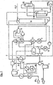
- FIG. 1 shows an indentation method with a NH 3 evaporator 1, a NH 3 gas preheater 2, a NH 3 gas filter 3, a NH 3 air mixer 4, an air filter 5, an air compressor 6, an air dryer 20 according to the invention, a NH 3 burner 7 with a La Mont desiccant boiler, a residual gas heater 8, a gas cooler 9, an absorption tower 13, an HNO 3 degasser 14, an air overnight dryer 22, a residual gas preheater 19, a NO x reactor 21, a residual gas expansion turbine 15 , a steam drum 16, a condensing steam turbine 17, and a condenser 18.
- Liquid ammonia is supplied at a pressure of about 16 bar abs, and a temperature of about 25 ° C and fed to the NH 3 evaporator 1. This is approximately below an evaporation pressure of 14 bar abs., Which corresponds to an evaporation temperature of 36 ° C.
- the liquid ammonia is almost completely evaporated at variable temperatures.
- the evaporation temperature increases depending on the water accumulation in the evaporator.
- the pressure in the evaporator system can be adjusted by varying the levels and the low pressure steam or pressure.
- the vaporized ammonia is heated to 140 ° C after passing through a mist eliminator in the steam-heated NH 3 gas preheater 2 and possibly entrained solid components are separated in the NH 3 gas filter 3.
- the compressor of the turbo set - consisting of air compressor 6, residual gas expansion turbine 15 and condensing steam turbine 17 - sucks the atmospheric, moist, d. H. loaded with steam process air 23 through the air filter 5 and compresses it to 12 bar abs. with a temperature of about 250 ° C.
- This air stream is dried according to the invention, it being provided in this example to remove as much moisture as possible so that a nitric acid concentration of 76% is achieved.
- the air dryer 20 used in the example has an integrated air / air heat exchanger, which cools the air flowing into the air dryer 20 to about 20 to 40 ° C. Thereafter, the pre-cooled air is cooled by means of cold water in a built-in air dryer 20, indirect-acting cooler to about 1 ° C, the moisture entrained by the air precipitates due to dew point of the air at the radiator surfaces and is separated from the air. As a result, the air leaving the radiator has a reduced water charge compared with its entry state, the air is now dried.
- the dried air is now passed to the heat-absorbing side of the integrated air dryer 20 air / air heat exchanger, on which side, the dried air is heated to 220 ° C.
- the process air 24 (primary air) and the ammonia gas are fed to the NH 3 air mixer 4.
- the ammonia content in the mixed gas is kept constant by a ratio control at about 10.1% by volume.
- the ammonia oxidizes on a Pt-Rh catalyst at a temperature of 900 ° C. to form nitrogen oxide.
- the hot combustion gases are passed through the La Mont waste heat boiler and the residual gas heater 8 structurally connected to the NH 3 burner 7, in which the heat of reaction, which is formed during the oxidation to NO and NO 2 , almost completely for steam generation and asmaschinesenergle (Residual gas expansion turbine 15) are exploited.
- the cooling takes place with Krelslaufkühlement to about 50 ° C, the majority of the reaction water condenses from the combustion and forms nitric acid with a concentration of about 44 to 50% by weight.
- This acid is from a (not In FIG. 1 shown) Acid condensate pump conveyed into the absorption tower 13 on a sieve plate corresponding acid concentration.
- the process air 25 (secondary air) is cooled in the residual gas preheater to about 60 ° C to 80 ° C, where it gives off its heat to the residual gas leaving the absorption tower 13.
- the process air 25 is used in the HNO 3 degasser 14, also referred to as a bleaching column, for blowing the crude acid before it is loaded with nitrous gas and admixed with the main gas stream prior to absorption.
- HNO 3 degasser 14 Before it performs this function in the HNO 3 degasser 14, it is washed with product-nitric acid in the air-night dryer 22 according to the invention, which is designed in this example as an HNO 3 scrubber, and thus subsequently dried.
- the remaining NO gas enters the absorption tower 13.
- This is equipped with sieve plates.
- the formation of nitric acid takes place in countercurrent of NO gas and process water, which is placed on the top soil.
- NO 2 and HNO 3 the acid concentration decreases as a result of decreasing NO 2 concentration in the direction of the upper end of the tower.
- the resulting heat of reaction and part of the sensible heat is discharged via cooling coils, which are located on the sieve plates, to the circulation cooling water.
- the acid is withdrawn from the 1st, 2nd or 3rd sieve bottom (counted from below) of the absorption tower 13.
- the withdrawn crude acid is conveyed into the HNO 3 degasser 14 equipped with Pall rings and freed from the physically dissolved nitrogen oxides in countercurrent with the process air 25 (secondary air).
- nitric acid leaving the HNO 3 degasser 14 is finished nitric acid, another part is used to wash the secondary air in the air after-dryer 22.
- the thus diluted nitric acid is either added to the condensate of the gas cooler 9 or applied directly to a sieve bottom of the absorption tower 13 of the same concentration.
- the residual gas is released from the absorption. After absorption, the residual gas is gradually heated from 25 ° C and that in the residual gas preheater 19 against secondary air and in the residual gas heater 8 against NO gas to about 350 ° C. After the catalytic denitrification in the NO x reactor 21, it is expanded in the residual gas expansion turbine 15.
- FIG. 2 shows a two-pressure process with a NH 3 evaporator 1, a NH 3 -Gasvor lockerr 2, a NH 3 gas filter 3, a NH 3 -air mixer 4, an air filter 5, an air compressor 6, an air dryer 20 according to the invention, a NH 3 burner 7 with La Mont waste heat boiler, a residual gas heater 8, a gas cooler 9, an NO compressor 10, a residual gas heater 11, a gas cooler 12, an absorption tower 13, an HNO 3 degasser 14, an air after-dryer 22, a residual gas Preheater 19, a residual gas expansion turbine 15, a steam drum 16, a condensation steam turbine 17 and a condenser 18th
- Liquid ammonia is abs with a pressure of approx. 11 bar. and a temperature of about 25 ° C and supplied to the NH 3 evaporator 1. This is approximately below an evaporation pressure of 7.0 bar abs., Which corresponds to an evaporation temperature of 14 ° C.
- the liquid ammonia is almost completely evaporated at variable temperatures. The evaporation temperature increases depending on the water accumulation in the evaporator.
- the pressure in the evaporator system can be adjusted by varying the levels and the amounts of cooling water.
- the vaporized ammonia is heated to 80 ° C after passing through a mist eliminator in the steam-heated NH 3 gas preheater 2 and possibly entrained solid components are separated in the NH 3 gas filter 3.
- the compressor of the turbo set - consisting of air compressor 6, NO compressor 10, residual gas expansion turbine 15 and condensing steam turbine 17 - sucks the atmospheric, moist, d. H.
- Process air 23 charged with steam through the air filter 5 compresses it to 5.6 bar abs. with a temperature of about 254 ° C.
- This air stream is dried according to the invention, it being provided in this example to remove as much moisture as possible so that a nitric acid concentration of 76% is achieved.
- the air dryer 20 used in the example has an integrated air / air heat exchanger, which cools the air flowing into the air dryer 20 to about 20 to 40 ° C. Thereafter, the pre-cooled air is cooled by means of cold water in a built-in air dryer 20, indirect-acting cooler to about 1 ° C, wherein the entrained by the air moisture precipitates due to dew point of the air at the radiator surfaces and is separated from the air. As a result, the air leaving the radiator has a reduced water charge compared with its entry state, the air is now dried.
- the dried air now becomes the heat-absorbing side of the air-to-air heat exchanger integrated in the air dryer 20 on which side the dried air is heated up again to 220 ° C.
- the process air 24 (primary air) and the ammonia gas are fed to the NH 3 air mixer 4.
- the ammonia content in the mixed gas is kept constant by a ratio control at about 10.2% by volume.
- the ammonia oxidizes on a Pt-Rh catalyst at a temperature of 890 ° C. to form nitrogen oxide.
- the hot combustion gas is passed through the La Mont waste heat boiler and the residual gas heater 8 which is structurally connected to the NH 3 burner 7, in which the heat of reaction, which is formed during the oxidation to NO and NO 2 , almost completely for steam generation and as drive energy (residual gas -Enttsciencesturbine 15) are exploited.
- the cooling is done with circulating cooling water to about 50 ° C, the majority of the reaction water condenses from the combustion and nitric acid forms with a concentration of about 44 to 50% by weight.
- This acid is from a (not in FIG. 2 shown) acid condensate pump in the absorption tower 13 promoted to a sieve tray corresponding acid concentration.
- the cooled combustion gas from the NO compressor 10 is further compressed to 11 bar, whereby it is heated.
- the heated gas is cooled in the residual gas heater 11 and the gas cooler 12 to 55 ° C, with further nitric acid forms, which is also promoted in the absorption tower 13 to a sieve plate corresponding acid concentration.
- the process air 25 (secondary air) is cooled in the residual gas preheater 19 to about 60 ° C to 80 ° C, wherein it gives off its heat to the residual gas leaving the absorption tower 13.
- the process air 25 is used in the HNO 3 degasser 14, also referred to as a bleaching column, for blowing the crude acid before it is loaded with nitrous gas and admixed with the main gas stream prior to absorption.
- HNO 3 degasser 14 Before she performs this function in the HNO 3 degasser 14, it is in the air dryer according to the invention 22, - is executed in this example as HNO 3 scrubber - washed with product nitric acid and thus dried.
- the remaining NO gas enters the absorption tower 13.
- This is equipped with sieve plates.
- the formation of nitric acid takes place in countercurrent of NO gas and process water, which is placed on the top soil.
- the acid concentration decreases as a result of decreasing NO 2 concentration in the direction of the upper end of the tower.
- the resulting heat of reaction and part of the sensible heat is discharged via cooling coils, which are located on the sieve plates to the Kreislaufkühlwasser.
- the acid is withdrawn from the 1st, 2nd or 3rd sieve bottom (counted from below) of the absorption tower 13.
- the withdrawn crude acid is conveyed into the HNO 3 degasser 14 equipped with Pall rings and freed from the physically dissolved nitrogen oxides in countercurrent with the process air 25 (secondary air).
- nitric acid leaving the HNO 3 degasser 14 is finished nitric acid, another part is used to wash the secondary air in the air after-dryer 22.
- the thus diluted nitric acid is either added to the condensate of the gas cooler 9 or fed directly to a sieve tray of the absorption tower 13, on which sieve tray the same concentration prevails
- the residual gas After absorption, the residual gas is gradually heated from 25 ° C in the residual gas preheater 19 against secondary air, and in the Restgaserhitzem 8 and 11 against NO gas to about 350 ° C. Thereafter, it is relaxed in the residual gas turbine 15.
Landscapes
- Chemical & Material Sciences (AREA)
- Organic Chemistry (AREA)
- Chemical Kinetics & Catalysis (AREA)
- Inorganic Chemistry (AREA)
- Treating Waste Gases (AREA)
- Organic Low-Molecular-Weight Compounds And Preparation Thereof (AREA)
- Drying Of Gases (AREA)
Abstract
Description
Die vorliegende Erfindung richtet sich auf ein Verfahren zur Herstellung von Salpetersäure, wie es beispielsweise in der
Zur Herstellung der Salpetersäure wird zunächst Ammoniak NH3 mit Luft reaktiv umgesetzt und Stickstoffoxid NO erzeugt:
4 NH3 + 5 O2 -----> 4 NO + 6 H2O + 907,3 kJ.
To produce the nitric acid, ammonia NH 3 is first reacted with air in a reactive manner and nitrogen oxide NO is produced:
4 NH 3 + 5 O 2 -----> 4 NO + 6 H 2 O + 907.3 kJ.
Das dabei anfallende Stickstoffoxid NO wird dann zu Stickstoffdioxid NO2 aufoxidiert:
2 NO + O2 -----> 2 NO2 + 113,1 kJ.
The resulting nitric oxide NO is then oxidized to nitrogen dioxide NO 2 :
2 NO + O 2 -----> 2 NO 2 + 113.1 kJ.
Abschließend wird das so gewonnene Stickstoffdioxid NO2 in Wasser absorbiert und es entsteht die Salpetersäure:
4 NO2 + O2 + 2 H2O -----> 4 HNO3 + 256,9 ./. 390,3 kJ.
Finally, the nitrogen dioxide NO 2 thus obtained is absorbed in water and the nitric acid is produced:
4NO 2 + O 2 + 2H 2 O -----> 4HNO 3 + 256.9 ./. 390.3 kJ.
Damit möglichst viel vom gewonnenen Stickstoffdioxid NO2 vom Wasser absorbiert wird, geschieht die Absorption bei erhöhtem Druck. Absorbiert wird vorzugsweise bei Drucken zwischen 4 bis 14 bar.So that as much as possible of the nitrogen dioxide NO 2 is absorbed by the water, absorption takes place at elevated pressure. Absorbed is preferably at pressures between 4 to 14 bar.
Der für die Umsetzung des als Rohstoff eingesetzten Ammoniaks benötigte Sauerstoff wird als Luftsauerstoff zugeführt. Dazu wird die Prozessluft verdichtet und auf einen Druck gebracht, der sowohl der Oxidationsreaktion wie auch der Absorptlonsreaktion angepasst ist.The oxygen required for the conversion of the ammonia used as raw material is supplied as atmospheric oxygen. For this purpose, the process air is compressed and brought to a pressure that is adapted to both the oxidation reaction as well as the Absorptlonsreaktion.
Die Energie zur Kompression der Luft wird einesteils mittels Entspannung des aus der Absorption austretenden Restgases auf Umgebungsdruck und anderenteils durch die Verwertung derbel den Umsetzungen freigesetzten Wärmen gewonnen.The energy for compression of the air is partly recovered by relaxing the residual gas leaving the absorption to ambient pressure and partly by utilizing the heat released in the reactions.
Die in verschiedenen Ausführungen errichteten Salpetersäureanlagen sind an die speziellen Anforderungen ihres jeweiligen Standortes angepasst.The nitric acid plants built in different versions are adapted to the special requirements of their respective location.
Elnsträngige Salpetersäureanlagen werden üblicherweise mit Nenn-Kapazitäten zwischen 100 bis 1 000 Tonnen Tagesproduktion Salpetersäure errichtet. Bei Verdoppelung des Reaktionsteils können somit einsträngig bis zu 2 000 Tonnen Tagesproduktion erreicht werden.Single-stranded nitric acid plants are usually constructed with nominal capacities between 100 to 1,000 tons daily nitric acid production. When the reaction part is doubled, it is thus possible to achieve single-stranded up to 2,000 tons of daily production.
Ist die geforderte Tagesproduktion gering oder besitzt ein Standort vergleichsweise niedrigere Energiepreise, so wird die Salpetersäure-Anlage vorzugsweise nach dem Mono-Hochdruck-Verfahren ausgeführt. Bei diesem Verfahren erfolgt die Verbrennung des Ammoniaks und die Absorption der Stickstoffoxide bei etwa gleichem Druck von ca. 10 bar.If the required daily production is low or if a location has comparatively lower energy prices, then the nitric acid plant is preferably carried out by the mono-high-pressure method. In this method, the combustion of ammonia and the absorption of nitrogen oxides at about the same pressure of about 10 bar.
Sind große Nenn-Kapazitäten und/oder höhere Säurekonzentrationen gefordert, bietet eine nach dem Zweidruck-Verfahren ausgeführte Salpetersäureanlage die wirtschaftlichere Lösung.If large nominal capacities and / or higher acid concentrations are required, a nitric acid plant designed according to the two-pressure process offers the more economical solution.
Beim Zweidruck-Verfahren geschieht die Verbrennung des eingesetzten Ammoniaks bei einem ersten, und bei, - verglichen mit dem Absorptionsdruck -, niedrigerem Druck. Die bei der Verbrennung gebildeten nitrosen Gase, - auch Nitrosegas genannt -, werden nach der Kühlung mittels Nitrosegasverdichtung auf den zweiten Druck, den Absorptionsdruck, gebracht.In the two-pressure process, the combustion of the ammonia used takes place at a first, and at, compared to the absorption pressure, lower pressure. The nitrous gases formed during combustion, also called nitrous gas, are brought to the second pressure, the absorption pressure, after cooling by means of nitrous gas compression.
Die früher üblichen Anlagen mit Verbrennung bei Normaldruck und Mitteldruckabsorption sind heute durch die wirtschaftlicheren Eindruck- und Zweidruckverfahren abgelöst worden. Die produzierte Salpetersäure wird auch als unterazeotrope Salpetersäure bezeichnet, da sich beim eventuell nachgeschalteten Destillieren einer solchen Säure wegen der Bildung eines Azeotropes nur eine maximale Salpetersäurekonzentration von 68 % erreichen lässt. Zur Überwindung dieser Grenze sind in der Literatur eine große Anzahl von Verfahren vorgestellt worden.The previously common systems with combustion at atmospheric pressure and medium-pressure absorption have been replaced today by the more economical impression and two-pressure process. The nitric acid produced is also referred to as under-azeotropic nitric acid, since in the subsequent distillation of such an acid due to the formation of an azeotrope only a maximum nitric acid concentration of 68% can be achieved. To overcome this limit, a large number of methods have been proposed in the literature.
Oft jedoch werden von den Verbrauchern der Salpetersäure Säurekonzentrationen von nur knapp oberhalb dieser 68 % gewünscht, etwa bei der Verwendung der Salpetersäure für die Produktion von Adipinsäure, von Caprolactam, von Toluoldiisocyanat oder anderen Stoffen, bei denen eine Nitrierung durch Salpetersäure erfolgt Es ist von daher ein seit langem bestehendes Bedürfnis der Industrie, ein wirtschaftliches Verfahren zur Erzeugung von Salpetersäure im Bereich von 68 bis 76 % zur Verfügung zu haben.Often, however, consumers of nitric acid are only just above 68% desired, such as the use of nitric acid for the production of adipic acid, caprolactam, toluene diisocyanate or other substances in which nitration is carried out by nitric acid It is therefore a long-felt need of the industry to have an economical process for producing nitric acid in the range of 68 to 76%.
Die Aufgabe der Erfindung besteht daher darin, die bestehenden und bekannten Eindruck- und Zweidruckverfahren zur Herstellung von unterazeotroper Salpetersäure mit einfachen und wirtschaftlichen Mitteln dahingehend zu ertüchtigen, dass Salpetersäure bis zu einer Konzentration von 76 % damit hergestellt werden kann.The object of the invention is therefore to make the existing and known impression and two-pressure processes for the production of Unterazeotropic nitric acid with simple and economical means to the effect that nitric acid can be made up to a concentration of 76% with it.
Die Erfindung löst die Aufgabe, durch ein Verfahren zur Herstellung von Salpetersäure im Konzentrationsbereich von 67 bis 76 Gewichts-% nach dem Eindruck-Verfahren oder dem Zweidruck-Verfahren, in dem die Verbrennung des eingesetzten Ammoniaks mittels verdichteter Prozessluft (23,24) geschieht, welche dem Verfahren von außen zugeführt wird und welche in ihrem Wasserdampfgehalt reduziert wird, indem sie getrocknet wird, und das durch die Verbrennung gebildete Nitrosegas mindestens teilweise von Wasser absorbiert wird, wodurch Salpetersäure entsteht, wobei die zur Strippung der erzeugten Salpetersäure von gelöstem N02 und NO verwendete Prozessluft (25) durch Waschen mit Produkt-Salpetersäure in einem Luftnachtrockner (22) nachgetrocknet wird.The invention solves the problem by a process for the production of nitric acid in the concentration range of 67 to 76% by weight according to the impression process or the two-pressure process in which the combustion of the ammonia used by means of compressed process air (23,24), which is supplied to the process from the outside and which is reduced in its water vapor content by drying, and the nitrous gas formed by the combustion is at least partially absorbed by water, whereby nitric acid is formed, wherein the stripping of the nitric acid produced by dissolved
Der Erfindung liegt der Gedanke zugrunde, den Wassereintrag in die Produkt-Salpetersäure zu minimieren. Am Wassereintrag ist der Eintrag als Feuchte über die Luft, welche als Verbrennungsluft und als Strippluft in den HNO3-Entgaser eingetragen wird, erheblich beteiligt. Die Trocknung bewirkt, dass weniger Feuchte in die Produkt-Salpetersäure eingetragen wird.The invention is based on the idea to minimize the entry of water into the product nitric acid. At the water entry is the entry as humidity over the air, which is registered as combustion air and as stripping in the HNO 3 -Eggger involved significantly. The drying causes less moisture is introduced into the product nitric acid.
Alle vorgenannten Ausgestaltungen verwenden dieselbe Erfindungsidee, der Fachmann muss bei der Auslegung der Anlage oder einer eventuellen Nachrüstung anhand wirtschaftlicher Gesichtspunkte im Einzelfall entscheiden, wie weit die Trocknung der Luft zu gehen hat, um die gewünschte Wirkung zu erzielen und welcher der Luftströme dafür zu trocknen Ist. Zu berücksichtigende technische Kriterien hierzu sind die zu erwartende Wasserdampfbeladung der Luft am Einsatzort des Verfahrens, der Wirkungsgrad der geplanten oder bereits in Betrieb befindlichen verfahrensgemäßen Verbrennungsvorrichtung von NH3 mit Luft zu NOx und der gewünschte Konzentrationsgrad der zu erzeugenden Salpetersäure. Üblicherweise werden ca. 80 % der eingesetzten Prozessluft für die Verbrennung und ca. 20 % für die Strippung genutzt, was eine wirtschaftlich optimierte Aufteilung der Trocknung verschledener Teilströme der Prozessluft ermöglicht.All of the aforementioned embodiments use the same inventive idea, the expert must decide in the design of the plant or a possible retrofitting from an economic point of view in each case, how far the drying of the air has to go to achieve the desired effect and which of the air streams is to dry it , Technical criteria to be considered for this are the expected water vapor loading of the air at the site of the process, the efficiency of the planned or already in operation process combustion apparatus of NH 3 with air to NO x and the desired concentration of the nitric acid to be produced. Usually, approx. 80% of the process air used is used for combustion and approx. 20% for the stripping, which enables an economically optimized division of the drying of diluted partial streams of the process air.
In weiterer Ausgestaltung der Erfindung ist vorgesehen, Kühlwasser mit einer Temperatur von 1 °C bis 20 °C für die Trocknung vorzusehen.In a further embodiment of the invention, it is provided to provide cooling water at a temperature of 1 ° C to 20 ° C for drying.
In weiterer Ausgestaltung der Erfindung ist vorgesehen, Kühlflüssigkeit von -25 °C bis 5 °C für die Trocknung vorzusehen.In a further embodiment of the invention, it is provided to provide cooling liquid of -25 ° C to 5 ° C for drying.
Die Anordnung der Trocknungsvorrichtung zur Trocknung der Prozessluftströme erfolgt zweckmäßigerweise hinter dem Luftverdichter, was jedoch zur Erfüllung der erfindungsgemäßen Aufgabe nicht unbedingt erforderlich ist.The arrangement of the drying device for drying the process air streams is advantageously carried out behind the air compressor, which is not absolutely necessary to achieve the object of the invention.
Die Erfindung wird im Folgenden an zwei Beispielen mit je einer Figur näher erläutert:The invention is explained in more detail below with reference to two examples, each with a figure:
Flüssiges Ammoniak wird mit einem Druck von ca. 16 bar abs, und einer Temperatur von ca. 25 °C angeliefert und dem NH3-Verdampfer 1 zugeführt. Dieser steht annähernd unter einem Verdampfungsdruck von 14 bar abs., was einer Verdampfungstemperatur von 36 °C entspricht. In dem mit Niederdruckdampf beaufschlagten NH3-Verdampfer 1 wird bei veränderlichen Temperaturen das flüssige Ammoniak nahezu vollständig verdampft. Dabei steigt die Verdampfungstemperatur abhängig von der Wasseranreicherung im Verdampfer an. Der Druck im Verdampfersystem kann durch Verändern der Stände und der Niederdruckdampfmenge bzw. dem -druck eingestellt werden.Liquid ammonia is supplied at a pressure of about 16 bar abs, and a temperature of about 25 ° C and fed to the NH 3 evaporator 1. This is approximately below an evaporation pressure of 14 bar abs., Which corresponds to an evaporation temperature of 36 ° C. In the charged with low pressure steam NH 3 evaporator 1, the liquid ammonia is almost completely evaporated at variable temperatures. The evaporation temperature increases depending on the water accumulation in the evaporator. The pressure in the evaporator system can be adjusted by varying the levels and the low pressure steam or pressure.
Das verdampfte Ammoniak wird nach Passieren eines Tropfenabscheiders im dampfbeheizten NH3-Gasvorwärmer 2 auf 140 °C erwärmt und im NH3-Gasfilter 3 werden evtl. noch mitgerissene feste Bestandteile abgetrennt.The vaporized ammonia is heated to 140 ° C after passing through a mist eliminator in the steam-heated NH 3 gas preheater 2 and possibly entrained solid components are separated in the NH 3 gas filter 3.
Der Verdichter des Turbosatzes - bestehend aus Luftverdichter 6, Restgas-Entspannungsturbine 15 und Kondensations-Dampfturbine 17 - saugt die für den Prozess benötigte atmosphärische, feuchte, d. h. mit Wasserdampf beladene Prozessluft 23 durch den Luftfilter 5 an und verdichtet sie auf 12 bar abs. mit einerTemperatur von ca. 250 °C.The compressor of the turbo set - consisting of air compressor 6, residual
Dieser Luftstrom wird erfindungsgemäß getrocknet, wobei in diesem Beispiel vorgesehen ist, möglichst soviel Feuchte zu entziehen, dass eine Salpetersäurekonzentration von 76 % erreicht wird. Der im Beispiel verwendete Lufttrockner 20 besitzt einen integrierten Luft/Luft-Wärmetauscher, der die in den Lufttrockner 20 einströmende Luft auf ca. 20 bis 40 °C abkühlt. Danach wird die vorgekühlte Luft mittels Kaltwasser In einem im Lufttrockner 20 Integrierten, indirekt wirkenden Kühler auf etwa 1 °C abgekühlt, wobei die von der Luft mitgeführte Feuchte infolge Taupunktunterschreitung der Luft an den Kühlerflächen ausfällt und so von der Luft abgetrennt wird. Hierdurch besitzt die den Kühler verlassende Luft eine verglichen mit ihrem Eintrittszustand verringerte Wasserbeladung, die Luft ist nun getrocknet.This air stream is dried according to the invention, it being provided in this example to remove as much moisture as possible so that a nitric acid concentration of 76% is achieved. The
Die getrocknete Luft wird nun an die wärmeaufnehmende Seite des im Lufttrockner 20 integrierten Luft/Luft-Wärmetauschers geleitet, auf welcher Seite die getrocknete Luft wieder auf 220 °C aufgeheizt wird.The dried air is now passed to the heat-absorbing side of the integrated
Nachdem die getrocknete und aufgeheizte Luft aus dem Lufttrockner 20 herausgeführt ist, wird sie in zwei Prozessluft-Ströme (Primär- und Sekundärluft) 24 und 25 aufgeteilt.After the dried and heated air is led out of the
Die Prozessluft 24 (Primärluft) und das Ammoniakgas werden dem NH3-Luftmischer 4 zugeführt. Der Ammoniak-Gehalt im Mischgas wird von einer Verhältnisregelung bei etwa 10,1 Vol.-% konstant gehalten. In dem nachfolgenden NH3-Brenner 7 oxidiert das Ammoniak an einem Pt-Rh-Katalysator bei einer Temperatur von 900°C zu Stickoxid. Die heißen Verbrennungsgase werden durch den baulich mit dem NH3-Brenner 7 verbundenen La Mont-Abhitzekessel und den Restgas-Erhitzer 8 geleitet, in denen die Reaktionswärmen, die bei der Oxidation zu NO und NO2 entstehen, nahezu vollständig zur Dampferzeugung und als Antriebsenergle (Restgas-Entspannungsturbine 15) ausgenutzt werden.The process air 24 (primary air) and the ammonia gas are fed to the NH 3
Im Gaskühler 9 erfolgt die Kühlung mit Krelslaufkühlwasser auf ca. 50°C, wobei der größte Teil des Reaktionswassers aus der Verbrennung kondensiert und sich Salpetersäure mit einer Konzentration von ca. 44 bis 50 Gewichts-% bildet.In the
Diese Säure wird von einer (nicht In
Die Prozessluft 25 (Sekundärluft) wird im Restgasvorwärmer auf ca. 60 °C bis 80 °C abgekühlt, wobei sie ihre Wärme an das Restgas, welches den Absorptionsturm 13 verlässt, abgibt. Die Prozessluft 25 wird im HNO3-Entgaser 14, auch als Bleichkolonne bezeichnet, zum Ausblasen der Rohsäure verwendet, bevor sie mit Nitrosegas beladen dem Hauptgasstrom vor der Absorption zugemischt wird. Bevor sie diese Funktion im HNO3-Entgaser 14 wahrnimmt, wird sie im erfindungsgemäßen Luftnachtrockner 22, der in diesem Beispiel als HNO3-Wäscher ausgeführt ist, mit Produkt-Salpetersäure gewaschen und somit nachgetrocknet.The process air 25 (secondary air) is cooled in the residual gas preheater to about 60 ° C to 80 ° C, where it gives off its heat to the residual gas leaving the
Mit einer Temperatur von ca. 56 °C gelangt das verbleibende NO-Gas in den Absorptionsturm 13. Dieser ist mit Siebböden ausgerüstet. Die Bildung von Salpetersäure findet im Gegenstrom von NO-Gas und Prozesswasser, welches auf den obersten Boden gegeben wird, statt. Entsprechend dem Gleichgewicht zwischen NO2 und HNO3 fällt die Säurekonzentration infolge abnehmender NO2-Konzentration in Richtung zum oberen Turmende ab. Die entstehende Reaktionswärme und ein Teil der fühlbaren Wärme wird über Kühlschlangen, die sich auf den Siebböden befinden, ans Kreislaufkühlwasser abgegeben. Je nach Konzentration wird die Säure vom 1., 2. bzw. 3. Siebboden (von unten gezählt) des Absorptionsturmes 13 abgezogen.With a temperature of about 56 ° C, the remaining NO gas enters the
Die abgezogenen Rohsäure wird in den mit Pall-Ringen ausgerüsteten HNO3-Entgaser 14 gefördert und mit der Prozessluft 25 (Sekundärluft) im Gegenstrom von den physikalisch gelösten Stickoxiden befreit.The withdrawn crude acid is conveyed into the HNO 3 degasser 14 equipped with Pall rings and freed from the physically dissolved nitrogen oxides in countercurrent with the process air 25 (secondary air).
Ein Teil der den HNO3-Entgaser 14 verlassenden Salpetersäure ist fertige Salpetersäure, ein anderer Teil wird zum Waschen der Sekundärluft im Luftnachtrockner 22 benutzt. Die dadurch verdünnte Salpetersäure wird entweder dem Kondensat des Gaskühlers 9 zugemischt oder direkt auf einen Siebboden des Absorptionsturms 13 gleicher Konzentration aufgegeben.Part of the nitric acid leaving the HNO 3 degasser 14 is finished nitric acid, another part is used to wash the secondary air in the air after-
Am Kopf des Absorptionsturms 13 wird das Restgas aus der Absorption abgegeben. Nach der Absorption wird das Restgas stufenweise von 25 °C aufgeheizt und zwar im Restgas-Vorwärmer 19 gegen Sekundärluft und im Restgas-Erhitzer 8 gegen NO-Gas auf ca. 350 °C. Nach der katalytischen Entstickung im NOx-Reaktor 21 wird es in der Restgas-Entspannungsturbine 15 entspannt.At the head of the
Flüssiges Ammoniak wird mit einem Druck von ca. 11 bar abs. und einer Temperatur von ca. 25 °C angeliefert und dem NH3-Verdampfer 1 zugeführt. Dieser steht annähernd unter einem Verdampfungsdruck von 7,0 bar abs., was einer Verdampfungstemperatur von 14 °C entspricht. In dem mit erwärmtem Rücklauf-Kühlwasser beaufschlagten NH3-Verdampfer 1 wird bei veränderlichen Temperaturen das flüssige Ammoniak nahezu vollständig verdampft. Dabei steigt die Verdampfungstemperatur abhängig von der Wasseranreicherung im Verdampfer an. Der Druck im Verdampfersystem kann durch Verändern der Stände und der Kühlwassermengen eingestellt werden.Liquid ammonia is abs with a pressure of approx. 11 bar. and a temperature of about 25 ° C and supplied to the NH 3 evaporator 1. This is approximately below an evaporation pressure of 7.0 bar abs., Which corresponds to an evaporation temperature of 14 ° C. In the charged with heated return cooling water NH 3 evaporator 1, the liquid ammonia is almost completely evaporated at variable temperatures. The evaporation temperature increases depending on the water accumulation in the evaporator. The pressure in the evaporator system can be adjusted by varying the levels and the amounts of cooling water.
Das verdampfte Ammoniak wird nach Passieren eines Tropfenabscheiders im dampfbeheizten NH3-Gasvorwärmer 2 auf 80°C erwärmt und im NH3-Gasfilter 3 werden evtl. noch mitgerissene feste Bestandteile abgetrennt.The vaporized ammonia is heated to 80 ° C after passing through a mist eliminator in the steam-heated NH 3 gas preheater 2 and possibly entrained solid components are separated in the NH 3 gas filter 3.
Der Verdichter des Turbosatzes - bestehend aus Luftverdichter 6, NO-Verdichter 10, Restgas-Entspannungsturbine 15 und Kondensations-Dampfturbine 17 - saugt die für den Prozess benötigte atmosphärische, feuchte, d. h. mit Wasserdampf beladene Prozessluft 23 durch den Luftfilter 5 an und verdichtetsie auf 5,6 bar abs. mit einer Temperatur von ca. 254 °C.The compressor of the turbo set - consisting of air compressor 6, NO
Dieser Luftstrom wird erfindungsgemäß getrocknet, wobei in diesem Beispiel vorgesehen ist, möglichst soviel Feuchte zu entziehen, dass eine Salpetersäurekonzentration von 76 % erreicht wird. Der Im Beispiel verwendete Lufttrockner 20 besitzt einen integrierten Luft/Luft-Wärmetauscher, der die in den Lufttrockner 20 einströmende Luft auf ca. 20 bis 40 °C abkühlt. Danach wird die vorgekühlte Luft mittels Kaltwasser in einem im Lufttrockner 20 integrierten, indirekt wirkenden Kühler auf etwa 1 °C abgekühlt, wobei die von der Luft mitgeführte Feuchte infolge Taupunktunterschreitung der Luft an den Kühlerflächen ausfällt und so von der Luft abgetrennt wird. Hierdurch besitzt die den Kühler verlassende Luft eine verglichen mit ihrem Eintrittszustand verringerte Wasserbeladung, die Luft ist nun getrocknet.This air stream is dried according to the invention, it being provided in this example to remove as much moisture as possible so that a nitric acid concentration of 76% is achieved. The
Die getrocknete Luft wird nun die wärmeaufnehmende Seite des im Lufttrockner 20 integrierten Luft/Luft-Wärmetauschers geleitet, auf welcher Seite die getrocknete Luft wieder auf 220 °C aufgeheizt wird.The dried air now becomes the heat-absorbing side of the air-to-air heat exchanger integrated in the
Nachdem die getrocknete und aufgeheizte Luft aus dem Lufttrockner 20 herausgeführt ist, wird sie in zwei Prozessluft-Ströme (Primär- und Sekundärluft) 24 und 25 aufgeteilt.After the dried and heated air is led out of the
Die Prozessluft 24 (Primärluft) und das Ammoniakgas werden dem NH3-Luftmischer 4 zugeführt. Der Ammoniak-Gehalt im Mischgas wird von einer Verhältnisregelung bei etwa 10,2 Vol.-% konstant gehalten. In dem nachfolgenden NH3-Brenner 7 oxidiert das Ammoniak an einem Pt-Rh-Katalysator bei einer Temperatur von 890 °C zu Stickoxid. Das heiße Verbrennungsgas wird durch den baulich mit dem NH3-Brenner 7 verbundenen La Mont-Abhitzekessel und den Restgaserhitzer 8 geleitet, In denen die Reaktionswärmen, die bei der Oxidation zu NO und NO2 entstehen, nahezu vollständig zur Dampferzeugung und als Antriebsenergie (Restgas-Entspannungsturbine 15) ausgenutzt werden.The process air 24 (primary air) and the ammonia gas are fed to the NH 3 air mixer 4. The ammonia content in the mixed gas is kept constant by a ratio control at about 10.2% by volume. In the subsequent NH 3 burner 7, the ammonia oxidizes on a Pt-Rh catalyst at a temperature of 890 ° C. to form nitrogen oxide. The hot combustion gas is passed through the La Mont waste heat boiler and the residual gas heater 8 which is structurally connected to the NH 3 burner 7, in which the heat of reaction, which is formed during the oxidation to NO and NO 2 , almost completely for steam generation and as drive energy (residual gas -Enttspannungsturbine 15) are exploited.
Im Gaskühler 9 erfolgt die Kühlung mit Kreislaufkühlwasser auf ca. 50 °C, wobei der größte Teil des Reaktionswassers aus der Verbrennung kondensiert und sich Salpetersäure mit einer Konzentration von ca. 44 bis 50 Gewichts-% bildet. Diese Säure wird von einer (nicht in
Danach wird das abgekühlte Verbrennungsgas vom NO-Verdichter 10 weiter auf 11 bar verdichtet, wobei es sich erhitzt. Das erhitzte Gas wird im Restgas-Erhitzer 11 und im Gaskühler 12 auf 55 °C abgekühlt, wobei sich weitere Salpetersäure bildet, welche ebenfalls in den Absorptionsturm 13 auf einen Siebboden entsprechender Säurekonzentration gefördert wird.Thereafter, the cooled combustion gas from the
Die Prozessluft 25 (Sekundärluft) wird im Restgas-Vorwärmer 19 auf ca. 60 °C bis 80 °C abgekühlt, wobei sie ihre Wärme an das Restgas, welches den Absorptionsturm 13 verlässt, abgibt. Die Prozessluft 25 wird im HNO3-Entgaser 14, auch als Bleichkolonne bezeichnet, zum Ausblasen der Rohsäure verwendet, bevor sie mit Nitrosegas beladen dem Hauptgasstrom vor der Absorption zugemischt wird. Bevor sie diese Funktion im HNO3-Entgaser 14 wahrnimmt, wird sie In dem erfindungsgemäßen Luftnachtrockner 22, - der in diesem Beispiel als HNO3-Wäscher ausgeführt ist -, mit Produkt-Salpetersäure gewaschen und somit nachgetrocknet.The process air 25 (secondary air) is cooled in the
Mit einer Temperatur von ca. 56°C gelangt das verbleibende NO-Gas in den Absorptionsturm 13. Dieser ist mit Siebböden ausgerüstet. Die Bildung von Salpetersäure findet im Gegenstrom von NO-Gas und Prozesswasser, welches auf den obersten Boden gegeben wird, statt. Entsprechend dem Gleichgewicht zwischen NO2 und HNO3 fällt die Säurekonzentration infolge abnehmender NO2-Konzentration in Richtung zum oberen Turmende ab. Die entstehende Reaktionswärme und ein Teil der fühlbaren Wärme wird über Kühlschlangen, die sich auf den Siebböden befinden, ans Kreislaufkühlwasser abgegeben. Je nach Konzentration wird die Säure vom 1., 2. bzw. 3. Siebboden (von unten gezählt) des Absorptionsturmes 13 abgezogen.With a temperature of about 56 ° C, the remaining NO gas enters the
Die abgezogenen Rohsäure wird in den mit Pall-Ringen ausgerüsteten HNO3-Entgaser 14 gefördert und mit der Prozessluft 25 (Sekundärluft) im Gegenstrom von den physikalisch gelösten Stickoxiden befreit.The withdrawn crude acid is conveyed into the HNO 3 degasser 14 equipped with Pall rings and freed from the physically dissolved nitrogen oxides in countercurrent with the process air 25 (secondary air).
Ein Teil der den HNO3-Entgaser 14 verlassenden Salpetersäure ist fertige Salpetersäure, ein anderer Teil wird zum Waschen der Sekundärluft im Luftnachtrockner 22 benutzt. Die dadurch verdünnte Salpetersäure wird entweder dem Kondensat des Gaskühlers 9 zugemischt oder direkt auf einen Siebboden des Absorptionsturms 13 aufgegeben, auf welchem Siebboden die gleiche Konzentration herrschtPart of the nitric acid leaving the HNO 3 degasser 14 is finished nitric acid, another part is used to wash the secondary air in the air after-
Nach der Absorption wird das Restgas stufenweise von 25°C aufgeheizt und zwar im Restgas-Vorwärmer 19 gegen Sekundärluft, und in den Restgaserhitzem 8 und 11 gegen NO-Gas auf ca. 350 °C. Danach wird es in der Restgasturbine 15 entspannt.After absorption, the residual gas is gradually heated from 25 ° C in the
- 11
- NH3-VerdampferNH 3 evaporator
- 22
- NH3-GasvorwärmerNH 3 gas preheater
- 33
- NH3-GasfilterNH 3 gas filter
- 44
- NH3-LuftmischerNH 3 air mixer
- 55
- Luftfilterair filter
- 66
- Luftverdichterair compressor
- 77
- NH3-BrennerNH 3 burner
- 88th
- Restgas-ErhitzerTail gas heater
- 99
- Gaskühlergas cooler
- 1010
- NO-VerdichterNO compressor
- 1111
- Restgas-ErhitzerTail gas heater
- 1212
- Gaskühlergas cooler
- 1313
- Absorptionsturmabsorption tower
- 1414
- HNO3-EntgaserENT 3 degasifier
- 1515
- Restgas-EntspannungsturbineTail-gas expansion turbine
- 1616
- Dampftrommelsteam drum
- 1717
- Kondensations-DampfturbineCondensing steam turbine
- 1818
- Kondensatorcapacitor
- 1919
- Restgas-VorwärmerResidual gas preheater
- 2020
- Lufttrocknerair dryer
- 2121
- NOx-ReaktorNOx reactor
- 2222
- Luftnachtrocknerair drier
- 2323
- Prozessluftprocess air
- 2424
- Prozessluft (Primärluft)Process air (primary air)
- 2525
- Prozessluft (Sekundärluft)Process air (secondary air)
Claims (3)
- Process for the production of nitric acid of a concentration ranging from 67% to 76% by weight using the mono-pressure or the dual-pressure process,• in which the applied ammonia is combusted with the aid of compressed process air (23,24) that is supplied to the process from outside and whose water vapour content is reduced by drying, and• in which the nitrous gas formed during combustion is at least partly absorbed by water, thus forming nitric acid,characterized in that
the process air (25), which is used for stripping the produced nitric acid to remove the dissolved NO2 and NO, is dried again by scrubbing it with product nitric acid in an air dryer (22). - Process according to claim 1,
characterized in that
the process air (23, 24, 25) is dried by heat exchange with cold water of a temperature between 1°C and 20°C. - Process according to claim 1,
characterized in that
the process air (23, 24, 25) is dried by heat exchange with a liquid coolant of a temperature between -25°C and 5°C.
Applications Claiming Priority (3)
| Application Number | Priority Date | Filing Date | Title |
|---|---|---|---|
| DE10011335A DE10011335A1 (en) | 2000-03-10 | 2000-03-10 | Production of nitric acid of specified concentration, useful in the production of adipic acid, caprolactam, toluene diisocyanate etc., by one- or 2-pressure combustion of ammonia and absorption uses dried air supply |
| DE10011335 | 2000-03-10 | ||
| PCT/EP2001/002365 WO2001068520A1 (en) | 2000-03-10 | 2001-03-02 | Method for producing nitric acid |
Publications (3)
| Publication Number | Publication Date |
|---|---|
| EP1261548A1 EP1261548A1 (en) | 2002-12-04 |
| EP1261548B1 EP1261548B1 (en) | 2007-09-12 |
| EP1261548B2 true EP1261548B2 (en) | 2016-04-20 |
Family
ID=7634003
Family Applications (1)
| Application Number | Title | Priority Date | Filing Date |
|---|---|---|---|
| EP01917053.9A Expired - Lifetime EP1261548B2 (en) | 2000-03-10 | 2001-03-02 | Method for producing nitric acid |
Country Status (9)
| Country | Link |
|---|---|
| US (1) | US7118723B2 (en) |
| EP (1) | EP1261548B2 (en) |
| JP (1) | JP4764589B2 (en) |
| AT (1) | ATE372958T1 (en) |
| AU (1) | AU2001244181A1 (en) |
| DE (2) | DE10011335A1 (en) |
| ES (1) | ES2290119T5 (en) |
| NO (1) | NO20024267D0 (en) |
| WO (1) | WO2001068520A1 (en) |
Families Citing this family (20)
| Publication number | Priority date | Publication date | Assignee | Title |
|---|---|---|---|---|
| DE10207627A1 (en) * | 2002-02-22 | 2003-09-11 | Uhde Gmbh | Process for the production of nitric acid |
| DE102007006889B3 (en) * | 2007-02-13 | 2008-04-24 | Uhde Gmbh | Preventing corrosion on and in the area of gas inlet connection by nitric acid condensation, comprises forming gas inlet opening in the form of annular gap by sleeve and producing secondary air by providing annular space with feed opening |
| ATE492512T1 (en) * | 2007-07-09 | 2011-01-15 | Basf Se | METHOD FOR PRODUCING NITRIC ACID WITH A CONCENTRATION IN THE RANGE OF 50 TO 77.8 WEIGHT |
| DE102008027232B3 (en) * | 2008-06-06 | 2009-09-03 | Uhde Gmbh | Blocking of the NO compressor and the residual gas expander in a nitric acid plant |
| EP2646368B1 (en) | 2010-12-01 | 2018-08-22 | The University of Sydney | Process for producing ammonium nitrate |
| AR084076A1 (en) * | 2010-12-01 | 2013-04-17 | Orica Int Pte Ltd | PROCESS TO PRODUCE NITRIC ACID |
| DE102011122142A1 (en) | 2011-12-22 | 2013-06-27 | Thyssenkrupp Uhde Gmbh | Process and apparatus for the production of nitric acid |
| DE102012000569A1 (en) | 2012-01-16 | 2013-07-18 | Thyssenkrupp Uhde Gmbh | Process for the colorless starting and stopping of nitric acid plants |
| DE102012000570A1 (en) | 2012-01-16 | 2013-07-18 | Thyssenkrupp Uhde Gmbh | Process and apparatus for the production of nitric acid |
| CN103011102B (en) * | 2012-12-21 | 2014-09-03 | 贵州开磷(集团)有限责任公司 | Cooling process for desalted water conveyed to nitric acid absorbing tower |
| FR3008626B1 (en) * | 2013-07-19 | 2015-08-07 | Arkema France | REACTOR FOR PREPARING HYDROGEN CYANIDE BY THE ANDRUSSOW PROCESS, EQUIPMENT COMPRISING SAID REACTOR AND METHOD USING SUCH EQUIPMENT |
| CN105217585B (en) * | 2014-06-04 | 2017-06-23 | 贵州芭田生态工程有限公司 | Double pressurized method nitric acid production plant |
| CN104310324A (en) * | 2014-10-14 | 2015-01-28 | 河北冀衡赛瑞化工有限公司 | Production method of electric draggable double-pressurizing nitric acid device |
| DE102016217765A1 (en) | 2016-09-16 | 2018-03-22 | Thyssenkrupp Ag | Arrangement and method for the condensation of a hot acid gas mixture |
| EP3372556A1 (en) | 2017-03-07 | 2018-09-12 | Casale Sa | A plant for the production of nitric acid, a related process and method of revamping |
| DE102017209257A1 (en) | 2017-06-01 | 2018-12-06 | Thyssenkrupp Ag | Process for the catalytic oxidation of ammonia gas |
| CN110721558A (en) * | 2019-11-18 | 2020-01-24 | 安徽金禾实业股份有限公司 | Method for drying and concentrating air entering furnace of nitric acid device |
| DE102020200235A1 (en) * | 2020-01-10 | 2021-07-15 | Thyssenkrupp Ag | Process and plant for the production of nitric acid |
| EP4015451A1 (en) * | 2020-12-17 | 2022-06-22 | Yara International ASA | Mono-pressure plant for the production of nitric acid and method for operating same |
| EP4163488A1 (en) * | 2021-10-08 | 2023-04-12 | Alfa Laval Corporate AB | An arrangement for preparing a gaseous ammonia based fuel to be combusted in a boiler and a method thereof |
Citations (3)
| Publication number | Priority date | Publication date | Assignee | Title |
|---|---|---|---|---|
| GB502155A (en) † | 1934-12-03 | 1939-03-13 | Tadeusz Chmura | Method of oxidation of ammonia |
| DE1916814A1 (en) † | 1969-03-28 | 1970-11-05 | Pintsch Bamag Ag | Process for the production of nitric acid of various concentrations |
| DE2148329A1 (en) † | 1971-09-28 | 1973-04-05 | Uhde Gmbh Friedrich | PROCESS FOR THE PRODUCTION OF NITRIC ACID |
Family Cites Families (4)
| Publication number | Priority date | Publication date | Assignee | Title |
|---|---|---|---|---|
| DE2856589B1 (en) * | 1978-12-29 | 1980-03-27 | Davy Internat Ag | Method and device for the time-limited drive of the turbine (s) coupled with the air and / or the nitrous gas compressor in a plant for the production of nitric acid |
| US4367204A (en) * | 1979-05-04 | 1983-01-04 | Budapesti Muszaki Egyetem | Process for the recirculation of nitrogen oxides |
| JPS6128442A (en) * | 1983-03-16 | 1986-02-08 | リンデ・アクチエンゲゼルシヤフト | Method and device for cooling gas current before compressionand/or on compression |
| ES2177162T3 (en) * | 1998-03-26 | 2002-12-01 | Uhde Gmbh | PROCEDURE AND INSTALLATION FOR PREPARATION OF NITRIC ACID. |
-
2000
- 2000-03-10 DE DE10011335A patent/DE10011335A1/en not_active Withdrawn
-
2001
- 2001-03-02 EP EP01917053.9A patent/EP1261548B2/en not_active Expired - Lifetime
- 2001-03-02 WO PCT/EP2001/002365 patent/WO2001068520A1/en active IP Right Grant
- 2001-03-02 AT AT01917053T patent/ATE372958T1/en not_active IP Right Cessation
- 2001-03-02 JP JP2001567627A patent/JP4764589B2/en not_active Expired - Fee Related
- 2001-03-02 US US10/220,361 patent/US7118723B2/en not_active Expired - Fee Related
- 2001-03-02 DE DE50113004T patent/DE50113004D1/en not_active Expired - Fee Related
- 2001-03-02 ES ES01917053.9T patent/ES2290119T5/en not_active Expired - Lifetime
- 2001-03-02 AU AU2001244181A patent/AU2001244181A1/en not_active Abandoned
-
2002
- 2002-09-06 NO NO20024267A patent/NO20024267D0/en not_active Application Discontinuation
Patent Citations (3)
| Publication number | Priority date | Publication date | Assignee | Title |
|---|---|---|---|---|
| GB502155A (en) † | 1934-12-03 | 1939-03-13 | Tadeusz Chmura | Method of oxidation of ammonia |
| DE1916814A1 (en) † | 1969-03-28 | 1970-11-05 | Pintsch Bamag Ag | Process for the production of nitric acid of various concentrations |
| DE2148329A1 (en) † | 1971-09-28 | 1973-04-05 | Uhde Gmbh Friedrich | PROCESS FOR THE PRODUCTION OF NITRIC ACID |
Non-Patent Citations (3)
| Title |
|---|
| "The compact plant", NITROGEN, vol. 215, 26 June 1995 (1995-06-26), LONDON, pages 32 - 33 † |
| BEITZ W.; KÜTTNER K.-H.: "Taschenbuch für den Maschinenbau", vol. 15, 1983, SPRINGER VERLAG, TOKYO, article "Luftbefeuchter - Luftentfeuchter - Schalldämpfer", pages: 677 † |
| HÄNGGELI W.: "Expansionstrurbinen für die Herstellung von Salpetersäure", TECHNISCHE RUNDSCHAU SULZER, vol. 2, 1 January 1986 (1986-01-01), WINTERTHUR, pages 29 - 31 † |
Also Published As
| Publication number | Publication date |
|---|---|
| EP1261548B1 (en) | 2007-09-12 |
| WO2001068520A1 (en) | 2001-09-20 |
| US7118723B2 (en) | 2006-10-10 |
| AU2001244181A1 (en) | 2001-09-24 |
| NO20024267L (en) | 2002-09-06 |
| DE10011335A1 (en) | 2001-09-20 |
| ES2290119T5 (en) | 2016-07-04 |
| ES2290119T3 (en) | 2008-02-16 |
| JP4764589B2 (en) | 2011-09-07 |
| EP1261548A1 (en) | 2002-12-04 |
| JP2003527284A (en) | 2003-09-16 |
| DE50113004D1 (en) | 2007-10-25 |
| US20030143148A1 (en) | 2003-07-31 |
| ATE372958T1 (en) | 2007-09-15 |
| NO20024267D0 (en) | 2002-09-06 |
Similar Documents
| Publication | Publication Date | Title |
|---|---|---|
| EP1261548B2 (en) | Method for producing nitric acid | |
| EP2382028B1 (en) | Method for separating carbon dioxide from an exhaust gas of a fossil fired power plant | |
| DE112020000100B4 (en) | FLUE GAS LOW TEMPERATURE ADSORPTION DENITRIATION SYSTEM AND PROCESS | |
| EP0335441A1 (en) | Process for the purification of flue gases | |
| EP2566603B1 (en) | Method for the catalytic removal of carbon dioxide and sulphur dioxide from exhaust gases | |
| EP1602401B2 (en) | Method and apparatus for partial condensation which is poor in aerosols | |
| DE2304784C2 (en) | Method and device for cleaning exhaust gases | |
| EP3720815A1 (en) | Method for providing co2 for synthesizing urea from flue gas and syngas | |
| DE3032470C2 (en) | Process for removing carbon dioxide from gases | |
| DE2809474C2 (en) | ||
| WO2013107490A1 (en) | Method and device for producing nitric acid | |
| EP0254362A1 (en) | Process for the purification of flue gases | |
| DD242755A5 (en) | METHOD FOR REGENERATING A LOADED DETERGENT | |
| EP3423401B1 (en) | Process and device for the preparation of sulfuric acid | |
| DE1091095B (en) | Process for the production of nitric acid | |
| DE10332794A1 (en) | Improving the performance of a Claus unit for process gas desulfurization comprises selectively removing water from the process gas to increase the sulfur yield | |
| DE3525721A1 (en) | Process for utilizing waste heat | |
| DE1956908C3 (en) | Preparation of a hydroxylammonium salt solution | |
| DE3517531A1 (en) | Process for extracting ammonia from hydrogen sulphide- and/or carbon dioxide-containing aqueous ammonia | |
| DE3117077C2 (en) | ||
| DE3428452A1 (en) | Process and reactor for the catalytic conversion of hydrogen sulphide into elemental sulphur | |
| DE2143583C3 (en) | Process for the production of urea | |
| DE3918212A1 (en) | Process and apparatus for recovery of nitrogen oxides from industrial plants | |
| WO2023056495A1 (en) | Process and plant for producing cement clinker | |
| DD202537A5 (en) | METHOD FOR THE REMOVAL OF UREA, AMMONIA AND CARBON DIOXIDE FROM PREVENTATED WAESSREN SOLUTIONS |
Legal Events
| Date | Code | Title | Description |
|---|---|---|---|
| PUAI | Public reference made under article 153(3) epc to a published international application that has entered the european phase |
Free format text: ORIGINAL CODE: 0009012 |
|
| 17P | Request for examination filed |
Effective date: 20020725 |
|
| AK | Designated contracting states |
Kind code of ref document: A1 Designated state(s): AT BE CH CY DE DK ES FI FR GB GR IE IT LI LU MC NL PT SE TR |
|
| AX | Request for extension of the european patent |
Free format text: AL;LT;LV;MK;RO;SI |
|
| RAP1 | Party data changed (applicant data changed or rights of an application transferred) |
Owner name: UHDE GMBH |
|
| 17Q | First examination report despatched |
Effective date: 20061219 |
|
| GRAP | Despatch of communication of intention to grant a patent |
Free format text: ORIGINAL CODE: EPIDOSNIGR1 |
|
| GRAS | Grant fee paid |
Free format text: ORIGINAL CODE: EPIDOSNIGR3 |
|
| GRAA | (expected) grant |
Free format text: ORIGINAL CODE: 0009210 |
|
| AK | Designated contracting states |
Kind code of ref document: B1 Designated state(s): AT BE CH CY DE DK ES FI FR GB GR IE IT LI LU MC NL PT SE TR |
|
| REG | Reference to a national code |
Ref country code: GB Ref legal event code: FG4D Free format text: NOT ENGLISH |
|
| REG | Reference to a national code |
Ref country code: CH Ref legal event code: EP |
|
| REF | Corresponds to: |
Ref document number: 50113004 Country of ref document: DE Date of ref document: 20071025 Kind code of ref document: P |
|
| REG | Reference to a national code |
Ref country code: IE Ref legal event code: FG4D Free format text: LANGUAGE OF EP DOCUMENT: GERMAN |
|
| REG | Reference to a national code |
Ref country code: SE Ref legal event code: TRGR |
|
| ET | Fr: translation filed | ||
| REG | Reference to a national code |
Ref country code: ES Ref legal event code: FG2A Ref document number: 2290119 Country of ref document: ES Kind code of ref document: T3 |
|
| NLV1 | Nl: lapsed or annulled due to failure to fulfill the requirements of art. 29p and 29m of the patents act | ||
| GBV | Gb: ep patent (uk) treated as always having been void in accordance with gb section 77(7)/1977 [no translation filed] | ||
| PG25 | Lapsed in a contracting state [announced via postgrant information from national office to epo] |
Ref country code: NL Free format text: LAPSE BECAUSE OF FAILURE TO SUBMIT A TRANSLATION OF THE DESCRIPTION OR TO PAY THE FEE WITHIN THE PRESCRIBED TIME-LIMIT Effective date: 20070912 Ref country code: GR Free format text: LAPSE BECAUSE OF FAILURE TO SUBMIT A TRANSLATION OF THE DESCRIPTION OR TO PAY THE FEE WITHIN THE PRESCRIBED TIME-LIMIT Effective date: 20071213 |
|
| REG | Reference to a national code |
Ref country code: IE Ref legal event code: FD4D |
|
| PG25 | Lapsed in a contracting state [announced via postgrant information from national office to epo] |
Ref country code: GB Free format text: LAPSE BECAUSE OF FAILURE TO SUBMIT A TRANSLATION OF THE DESCRIPTION OR TO PAY THE FEE WITHIN THE PRESCRIBED TIME-LIMIT Effective date: 20070912 Ref country code: PT Free format text: LAPSE BECAUSE OF FAILURE TO SUBMIT A TRANSLATION OF THE DESCRIPTION OR TO PAY THE FEE WITHIN THE PRESCRIBED TIME-LIMIT Effective date: 20080212 |
|
| PLBI | Opposition filed |
Free format text: ORIGINAL CODE: 0009260 |
|
| 26 | Opposition filed |
Opponent name: BASF SE Effective date: 20080609 |
|
| PLAX | Notice of opposition and request to file observation + time limit sent |
Free format text: ORIGINAL CODE: EPIDOSNOBS2 |
|
| PG25 | Lapsed in a contracting state [announced via postgrant information from national office to epo] |
Ref country code: DK Free format text: LAPSE BECAUSE OF FAILURE TO SUBMIT A TRANSLATION OF THE DESCRIPTION OR TO PAY THE FEE WITHIN THE PRESCRIBED TIME-LIMIT Effective date: 20070912 |
|
| BERE | Be: lapsed |
Owner name: UHDE G.M.B.H. Effective date: 20080331 |
|
| PG25 | Lapsed in a contracting state [announced via postgrant information from national office to epo] |
Ref country code: IE Free format text: LAPSE BECAUSE OF FAILURE TO SUBMIT A TRANSLATION OF THE DESCRIPTION OR TO PAY THE FEE WITHIN THE PRESCRIBED TIME-LIMIT Effective date: 20070912 Ref country code: MC Free format text: LAPSE BECAUSE OF NON-PAYMENT OF DUE FEES Effective date: 20080331 |
|
| REG | Reference to a national code |
Ref country code: CH Ref legal event code: PL |
|
| PLAF | Information modified related to communication of a notice of opposition and request to file observations + time limit |
Free format text: ORIGINAL CODE: EPIDOSCOBS2 |
|
| PLBB | Reply of patent proprietor to notice(s) of opposition received |
Free format text: ORIGINAL CODE: EPIDOSNOBS3 |
|
| PG25 | Lapsed in a contracting state [announced via postgrant information from national office to epo] |
Ref country code: CH Free format text: LAPSE BECAUSE OF NON-PAYMENT OF DUE FEES Effective date: 20080331 Ref country code: LI Free format text: LAPSE BECAUSE OF NON-PAYMENT OF DUE FEES Effective date: 20080331 |
|
| PG25 | Lapsed in a contracting state [announced via postgrant information from national office to epo] |
Ref country code: BE Free format text: LAPSE BECAUSE OF NON-PAYMENT OF DUE FEES Effective date: 20080331 |
|
| PGFP | Annual fee paid to national office [announced via postgrant information from national office to epo] |
Ref country code: FI Payment date: 20090313 Year of fee payment: 9 |
|
| PG25 | Lapsed in a contracting state [announced via postgrant information from national office to epo] |
Ref country code: CY Free format text: LAPSE BECAUSE OF FAILURE TO SUBMIT A TRANSLATION OF THE DESCRIPTION OR TO PAY THE FEE WITHIN THE PRESCRIBED TIME-LIMIT Effective date: 20070912 |
|
| PG25 | Lapsed in a contracting state [announced via postgrant information from national office to epo] |
Ref country code: AT Free format text: LAPSE BECAUSE OF NON-PAYMENT OF DUE FEES Effective date: 20080302 |
|
| PGFP | Annual fee paid to national office [announced via postgrant information from national office to epo] |
Ref country code: DE Payment date: 20090320 Year of fee payment: 9 Ref country code: SE Payment date: 20090312 Year of fee payment: 9 |
|
| PGFP | Annual fee paid to national office [announced via postgrant information from national office to epo] |
Ref country code: FR Payment date: 20090312 Year of fee payment: 9 |
|
| PG25 | Lapsed in a contracting state [announced via postgrant information from national office to epo] |
Ref country code: LU Free format text: LAPSE BECAUSE OF NON-PAYMENT OF DUE FEES Effective date: 20080302 |
|
| PG25 | Lapsed in a contracting state [announced via postgrant information from national office to epo] |
Ref country code: TR Free format text: LAPSE BECAUSE OF FAILURE TO SUBMIT A TRANSLATION OF THE DESCRIPTION OR TO PAY THE FEE WITHIN THE PRESCRIBED TIME-LIMIT Effective date: 20070912 |
|
| EUG | Se: european patent has lapsed | ||
| PG25 | Lapsed in a contracting state [announced via postgrant information from national office to epo] |
Ref country code: FI Free format text: LAPSE BECAUSE OF NON-PAYMENT OF DUE FEES Effective date: 20100302 |
|
| REG | Reference to a national code |
Ref country code: FR Ref legal event code: ST Effective date: 20101130 |
|
| PG25 | Lapsed in a contracting state [announced via postgrant information from national office to epo] |
Ref country code: FR Free format text: LAPSE BECAUSE OF NON-PAYMENT OF DUE FEES Effective date: 20100331 |
|
| PG25 | Lapsed in a contracting state [announced via postgrant information from national office to epo] |
Ref country code: DE Free format text: LAPSE BECAUSE OF NON-PAYMENT OF DUE FEES Effective date: 20101001 Ref country code: IT Free format text: LAPSE BECAUSE OF NON-PAYMENT OF DUE FEES Effective date: 20080331 |
|
| APBM | Appeal reference recorded |
Free format text: ORIGINAL CODE: EPIDOSNREFNO |
|
| APBP | Date of receipt of notice of appeal recorded |
Free format text: ORIGINAL CODE: EPIDOSNNOA2O |
|
| APAH | Appeal reference modified |
Free format text: ORIGINAL CODE: EPIDOSCREFNO |
|
| APBQ | Date of receipt of statement of grounds of appeal recorded |
Free format text: ORIGINAL CODE: EPIDOSNNOA3O |
|
| RAP2 | Party data changed (patent owner data changed or rights of a patent transferred) |
Owner name: THYSSENKRUPP UHDE GMBH |
|
| PG25 | Lapsed in a contracting state [announced via postgrant information from national office to epo] |
Ref country code: SE Free format text: LAPSE BECAUSE OF NON-PAYMENT OF DUE FEES Effective date: 20100303 |
|
| RAP2 | Party data changed (patent owner data changed or rights of a patent transferred) |
Owner name: THYSSENKRUPP INDUSTRIAL SOLUTIONS AG |
|
| APBU | Appeal procedure closed |
Free format text: ORIGINAL CODE: EPIDOSNNOA9O |
|
| PUAH | Patent maintained in amended form |
Free format text: ORIGINAL CODE: 0009272 |
|
| STAA | Information on the status of an ep patent application or granted ep patent |
Free format text: STATUS: PATENT MAINTAINED AS AMENDED |
|
| 27A | Patent maintained in amended form |
Effective date: 20160420 |
|
| AK | Designated contracting states |
Kind code of ref document: B2 Designated state(s): AT BE CH CY DE DK ES FI FR GB GR IE IT LI LU MC NL PT SE TR |
|
| REG | Reference to a national code |
Ref country code: DE Ref legal event code: R102 Ref document number: 50113004 Country of ref document: DE |
|
| REG | Reference to a national code |
Ref country code: ES Ref legal event code: DC2A Ref document number: 2290119 Country of ref document: ES Kind code of ref document: T5 Effective date: 20160704 |
|
| PGFP | Annual fee paid to national office [announced via postgrant information from national office to epo] |
Ref country code: ES Payment date: 20170315 Year of fee payment: 17 |
|
| REG | Reference to a national code |
Ref country code: ES Ref legal event code: FD2A Effective date: 20190904 |
|
| PG25 | Lapsed in a contracting state [announced via postgrant information from national office to epo] |
Ref country code: ES Free format text: LAPSE BECAUSE OF NON-PAYMENT OF DUE FEES Effective date: 20180303 |