Field of the invention
-
The invention relates to an arrangement for preparing a gaseous ammonia based fuel to be combusted in a boiler.
-
The invention also relates to a method for preparing a gaseous ammonia based fuel to be combusted in a boiler.
Background art
-
Marine engines powered by oil or gas are well known in the art. Oil and gas fired boilers for marine steam production are also well known in the art. Usually, the choice of fuel for the boiler operation is made in relation to the fuels selected for the marine engine operation. Thus, if the marine engine is powered by oil, the boiler is often powered by oil as well. However, the marine engine and the boiler may be powered by different fuels.
-
One drawback with most of the marine engines of today is marine air pollution, especially carbon dioxide (CO2), emitted from the marine engines when providing propulsion power. It is generally agreed that the CO2 emissions, as well as other greenhouse gas emissions, have to be decreased in view of environmental aspects. As a solution, alternative fuels are gaining traction in the marine industry. This includes fuels like biofuels, methanol, hydrogen, ammonia, and liquified natural gas (LNG). However, by introducing alternative fuels, other problems may occur, e.g. the possibilities of storing the alternative fuels. Further problems that may occur are the possibilities of igniting the alternative fuel and to keep the ignited alternative fuel as a stable burning flame.
-
In attempt to address some parts of this issue, document
JP2020183854 A discloses a heat engine which uses ammonia as main fuel, wherein liquified ammonia is evaporated in an evaporator before being supplied to the engine. It further discloses that the cold generated from the evaporator is supplied to a cooler by a cooling medium to enable external refrigeration and cooling.
-
However, as will be explained below, the prior art does not disclose an environmentally friendly marine arrangement which adequately addresses the set of design criteria of improving the flammability of the alternative fuel as well as keeping the ignited alternative fuel as a stable burning flame, and especially the prior art does not disclose how to provide an overall arrangement which may be used in a convenient manner over time when it comes to meeting said set of design criteria.
Summary of the disclosure
-
It is an object of the disclosure to provide an environmentally friendly marine arrangement which adequately addresses the set of design criteria of improving the flammability of the alternative fuel as well as keeping the ignited alternative fuel as a stable burning flame.
-
This object has been achieved by an arrangement for preparing a gaseous ammonia based fuel to be combusted, preferably combusted in a furnace or burner of a boiler system, the arrangement comprising:
an ammonia fuel supply system comprising:
- an evaporator being configured to vaporize liquified ammonia into gaseous ammonia by a first heating medium, and
- an ammonia heater being arranged after the evaporator and being configured to receive the gaseous ammonia from the evaporator and pre-heat the gaseous ammonia by a second heating medium or by an electrical heater.
-
The term "gaseous ammonia based fuel" is herein meant a gaseous fuel which comprises ammonia. The gaseous ammonia based fuel may comprise only gaseous ammonia. The gaseous ammonia based fuel may also comprise other gaseous fuels. The gaseous ammonia based fuel may also comprise air. Thus, the gaseous ammonia based fuel is a gaseous fuel in which at least a part of the gaseous fuel is gaseous ammonia. The amount of ammonia comprised in the gaseous ammonia based fuel may depend on the boiler in which the gaseous ammonia based fuel will be combusted.
-
With such a design it is facilitated to provide an efficient combustion of the gaseous ammonia based fuel in the boiler system and thereby it is facilitated to make use of a more environmentally friendly fuel for the combustion in the furnace or burner of the boiler system. Preferably, the ammonia is stored as liquified ammonia since the liquified ammonia takes less space compared to gaseous ammonia and thereby less storage space is needed. As the furnace or burner of the boiler system is designed to combust the ammonia based fuel in gaseous form, the liquified ammonia has to be transformed into gaseous ammonia before being supplied to the boiler. This transformation from liquified ammonia to gaseous ammonia is provided by the evaporator of the present disclosure. By introducing the evaporator to the arrangement, the possibilities of storing the ammonia as liquified ammonia and to transform the ammonia into gaseous ammonia before being supplied to the boiler is achieved. Preferably, the evaporator is a heat exchanger configured to vaporize the liquified ammonia. The heat exchanger may be e.g. a plate heat exchanger, or a shell and tube heat exchanger. The evaporator may be a boiler configured to vaporize the liquified ammonia. Preferably, the evaporator is designed in a resistant material which is able to handle liquified ammonia and gaseous ammonia.
-
The possibilities of igniting the ammonia and to keep the ammonia as a stable burning flame is crucial parameters for the boiler, since the power output of the boiler will be almost proportional to both a heating value and a flame velocity of the ammonia. The heating value is referring to energy content in the ammonia and this cannot be changed. Thus, both liquified ammonia and gaseous ammonia have the same heating value of 18.6 MJ/kg. The flame velocity describes the speed at which a flame will propagate through a quiescent, homogenous mixture of unburned reactants. Thus, basically, it is a number describing how fast a certain fuel may burn. The flame velocity may be improved. Thus, even though a mixture of ammonia and air has a lower heating value, if the flame velocity is increased, the power output of the boiler may still be increased. Liquified ammonia is in scientific sources typically said to have a flame velocity of 0.010 - 0.020 m/s, and best estimates are often said to be about 0.014 - 0.016 m/s. Gaseous ammonia is in scientific sources typically said to have a flame velocity of 0.03 - 0.13 m/s, and best estimates are often said to be about 0.07 - 0.09 m/s. The actual values vary dependent upon the actual situation and different scientific sources may therefore indicate different values. However, irrespective of the specific values, by vaporizing the liquified ammonia into gaseous ammonia, the flame velocity increases. This increase is from approximately 0.015 m/s to approximately 0.08 m/s. Moreover, the flame velocity may be further increased with an increased temperature of the gaseous ammonia. Thus, the evaporator is advantageous in that both the ammonia may be stored as liquified ammonia but also to improve the flame velocity of the ammonia.
-
By introducing the ammonia heater after the evaporator, the temperature of the gaseous ammonia may be further increased and thereby also the flame velocity of the gaseous ammonia. Preferably, the ammonia heater is a high temperature heat source configured to pre-heat the gaseous ammonia. The higher temperature the gaseous ammonia has, the higher flame velocity the gaseous ammonia will have. By increasing the temperature of the gaseous ammonia and thereby also the flame velocity of the gaseous ammonia, a flame ignition range, in which the ammonia becomes flammable, may be increased as well. By increasing the flame ignition range of the ammonia, the flammability of the gaseous ammonia may be improved. By increasing and improving the flammability of the gaseous ammonia, means for burning more ammonia in the boiler faster may be provided.
-
Thus, with the disclosed design, in which the evaporator is configured to vaporize the liquified ammonia and the ammonia heater is configured to pre-heat the vaporized ammonia, the flame velocity and the flame ignition range of the ammonia may be increased. Thereby, the flammability enhancement of the ammonia is increased and improved. Thus, a more efficient and flammable fuel to be combusted in the boiler is achieved.
-
It may in this context be noted that the term "after" may, but does not necessarily need to, mean that the ammonia heater is physically located after the evaporator. After is primarily intended to refer to a position as seen along the flow path of the ammonia. The ammonia heater is located after the evaporator as seen along the flow of the ammonia since the ammonia supplied to the ammonia heater is gaseous ammonia which has already passed the evaporator. If the ammonia heater is a module being physically separate from the evaporator, the ammonia heater may e.g. be located side by side with the evaporator.
-
It is advantageous to first vaporize the liquid ammonia into gaseous ammonia and thereafter heat the gaseous ammonia in an ammonia heater receiving the gaseous ammonia from the evaporator. The vaporization involves the provision of a significant amount energy to transfer the ammonia from liquid form to gaseous form, but the heating medium supplying this energy does not necessarily have to be a high temperature medium; it is basically sufficient that it is slightly above the vaporization temperature for the ammonia, or alternatively slightly above the desired output temperature of the gaseous ammonia from the evaporator. Preferred embodiments concerning the vaporization appear below. The pre-heating of the gaseous ammonia in the ammonia heater, on the other hand does not involve a phase transition and the heat provided by the second heating medium will mostly go directly to a raise in the temperature of the gaseous ammonia. Thus, a sufficiently high temperature on the heating medium is of more importance compared to in the vaporization step. These differences in the general physical behavior of the ammonia in the vaporization respectively the pre-heating makes it more efficient to perform the steps in two different steps, such that each step may be optimized considering the circumstances of each such step. This also makes it useful to use an electrical heater as the ammonia heater, since an electrical heater may be designed to quickly provide high temperatures and thereby heat the gaseous ammonia during start-up procedures and/or during continuous operation.
-
The arrangement may further comprise a mixer being arranged after the ammonia fuel supply system and being configured to receive the pre-heated gaseous ammonia from the ammonia fuel supply system, to receive air from an air supply system, and to mix the pre-heated gaseous ammonia and the air, and thereby provide the gaseous ammonia based fuel.
-
Preferably, the gaseous ammonia is supplied to the mixer via an outlet gaseous ammonia supply line from the ammonia fuel supply system. The air is preferably supplied to the mixer via an outlet air supply line from the air supply system. Thereby, the gaseous ammonia and the air are separately supplied to the mixer and are mixed together in the mixer. This is advantageous in that it facilitates to separately control the supply of gaseous ammonia and the air. Thus, it is facilitated to separately control e.g. the flow of the gaseous ammonia respectively the flow of the air. Thereby, it is possible to provide the gaseous ammonia based fuel comprising a desired amount of gaseous ammonia and air, respectively.
-
With such a design, in which the gaseous ammonia is mixed with air before the mixture is supplied to the boiler, it is ensured that a flammable mixture is available immediately when the mixture enters a furnace of the boiler. Thus, a more efficient and flammable fuel to be combusted in the furnace of the boiler is achieved.
-
Moreover, backfire prevention may be ensured by having sufficiently high flow velocity in feed pipes being arranged after the mixer. The flow velocity of the flammable mixture should be higher than the highest flame velocity at the present conditions. With the conditions discussed in this disclosure it is considered that the flow velocity should be higher than 0,08m/s. However, it may be noted that if e.g. the temperature is increased, the flame velocity increases and consequently the system should be designed such that the flow velocity still remains higher than the flame velocity.
-
The air supply system may comprise an air heater being arranged before the mixer, and being configured to pre-heat the air by the second heating medium or by a third heating medium, preferably by the second heating medium, or by an electrical heater, and to supply the pre-heated air to the mixer.
-
The air may be ambient air from outside, or from an interior room in which the air system and or boiler is located, such as e.g. an engine room of a land-based industry facility or an engine room of a marine vessel. The air heater is basically configured to pre-heat the air to as high temperature as practically is possible before supplying the pre-heated air to the mixer. Preferably, the air heater is a high temperature heat source configured to pre-heat the air.
-
With such a design, in which both the gaseous ammonia and the air is pre-heated, the provision of a powerful and stable flame is facilitated. Thus, the higher temperature the gaseous ammonia based fuel has, the higher flame velocity the gaseous ammonia based fuel will have. By increasing the temperature of the gaseous ammonia based fuel and thereby the flame velocity of the gaseous ammonia based fuel, a flame ignition range indicating the amount of gaseous ammonia in the gaseous ammonia based fuel, in which range the gaseous ammonia based fuel becomes flammable, may be increased as well. By increasing the flame ignition range of the gaseous ammonia based fuel, the flammability of the gaseous ammonia based fuel may be improved. By increasing and improving the flammability of the gaseous ammonia based fuel, means for burning more fuels in the boiler faster may be provided.
-
If the gaseous ammonia based fuel has a temperature of 25°C, a flame ignition range of 16-28% of the gaseous ammonia based fuel is flammable. If the gaseous ammonia based fuel has a temperature of 300°C, a flame ignition range of 13-34% of the gaseous ammonia based fuel is flammable. If the gaseous ammonia based fuel has a temperature of 400°C, a flame ignition range of 11-37% of the gaseous ammonia based fuel is flammable.
-
By pre-heating the gaseous ammonia and the air separately and thereafter mixing the pre-heated ammonia and the pre-heated air the provision of having a flexible arrangement is provided. Thus, it is possible to separately adjust the amount of gaseous ammonia and air in the gaseous ammonia based fuel. It is further possible to adjust the temperature of the gaseous ammonia and the air separately. By way of example, it is possible to prepare the gaseous ammonia based fuel such that the boiler may be able to operate with a combustion air surplus of 5-25%.
-
This may be further advantageous in that the airflow may be approximately about four to five times, based on a molar flow, higher than the gaseous ammonia airflow, thus ensuring more available heated air in the overall combustion process.
-
It may in this context be noted that the term "before" may, but does not necessarily need to, mean that the air heater is physically located before the mixer. Before is primarily intended to refer to a position as seen along the flow path of the air. The air heater is located before the mixer as seen along the flow of the air since the air supplied to the mixer is air which has already passed the air heater. If the air heater is a module being physically separate from the mixer, the air heater may e.g. be located side by side with the mixer.
-
The evaporator may be configured to vaporize the liquified ammonia into gaseous ammonia to an evaporator output temperature between -33 °C and +50°C.
-
The evaporator output temperature depends on a temperature of the liquified ammonia as well as a temperature of the first heating medium. Preferably, the temperature of the first heating medium may be varied depending on a desired evaporator output temperature. Preferably, the liquified ammonia may have a temperature which is slightly below -33°C when being supplied to the evaporator. The boiling point of ammonia is -33°C at normal atmospheric pressure and as the ammonia is stored in liquid state, the temperature of the liquid ammonia should be slightly below -33°C. Alternatively, or as a complement, the liquid ammonia may be stored under pressure. The temperature requirements of the evaporator may be relatively moderate since the liquified ammonia will vaporize when the temperature of the ammonia is above the boiling point -33°C. By moderate requirements, it is herein meant that it is not necessary to make use of a heating medium with really high temperature as the ammonia has a rather low boiling point. Thus, a requirement for the heating medium is that the heating medium should be able to transfer heat to the liquified ammonia such that the liquified ammonia will vaporize. However, depending on the available kind of first heating medium it may be useful to raise the temperature of the ammonia to some extent already in the evaporator. As mentioned above, the evaporator output temperature is preferably between -33°C and +50°C.
-
The first heating medium is chosen from a group consisting of seawater, cooling water from an engine, refrigerant from an air condition system, and thermal fluid from heaters and/or boilers.
-
The first heating medium may have as high temperature as practically possible such that the vaporized ammonia may have as high temperature as practically possible. However, as said above, the first heating medium should have a temperature such that the liquified ammonia will vaporize. Therefore, seawater, cooling water from the engine, refrigerant from an air condition system, or thermal fluid from heaters and/or boilers may be just fine as heating medium, as the temperature of the first heating medium just has to be above the boiling point of the ammonia, but preferably higher. In this context it may be noted that the thermal fluid from heaters and/or boilers typically refers to thermal fluid by which waste heat from the heater or boiler is transferred to the ammonia. It may e.g. be that the thermal fluid from the heater or boiler first has been transferred to a primary user and thereafter the thermal fluid is transferred to the evaporator such that any heat still present in the thermal fluid is used to vaporize the ammonia before the thermal fluid is returned to the heater or boiler to be heated for the primary purpose again. Thus, the evaporator may be a liquid to liquid type, a gas to gas type or a liquid to gas type. Which type evaporator to choose depends typically on which gives the best techno-economic performance taking into account both the arrangement as such and also neighboring systems; especially the neighboring systems supplying heating mediums, of the industry facility or marine vessel.
-
The first heating medium may be seawater in case the arrangement is positioned at the sea, e.g. on a ship, or in vicinity of the sea such that the seawater is easy to supply to the arrangement as the first heating medium. The first heating medium may be cooling water from an engine or refrigerant form the air condition system. The first medium may be thermal fluid from heaters and/or boilers. In such a case the engine or air condition system should preferably be arranged in vicinity to the arrangement such that the cooling water or refrigerant is easy to supply to the arrangement. This is advantageous in that no extra medium needs to be supplied to the arrangement, or to the vicinity of the arrangement, in order to being able to vaporize the liquified ammonia.
-
The ammonia heater may be configured to pre-heat the gaseous ammonia to an ammonia heater output temperature between 100°C and 300°C.
-
The ammonia heater output temperature depends on a temperature of the gaseous ammonia and on a temperature of the second heating medium. Preferably, the temperature of the second heating medium may be varied depending on a desired ammonia heater output temperature. It is considered that an ammonia heater output temperature above 300°C begins to set requirements on the temperature and flow of the second heating medium which could make the arrangement counter-productive in that the additional effort to increase the ammonia heater output temperature above 300°C becomes too cumbersome compared to the advantage achieved in the boiler function.
-
The second heating medium is chosen from a group consisting of steam, thermal fluid, or exhaust gas.
-
Preferably, the second heating medium has as high temperature as practically possible such that the pre-heated gaseous ammonia will have as high temperature as practically possible. The steam may originate from a boiler economizer. The exhaust gas may be exhaust gas originating from a main engine and/or an auxiliary engine. Preferably, the second heating medium has a temperature between 100°C and 400°C. The ammonia heater is configured to direct the steam, the exhaust gas, or the thermal fluid such that heat is transferred to the gaseous ammonia. Thus, the ammonia heater may be a gas/gas heater type, a fluid/gas heater type, or a steam/gas heater type.
-
Preferably, the boiler economizer, the main engine or the auxiliary engine should be comprised in the arrangement or arranged in vicinity to the arrangement. This is advantageous in that no extra medium needs to be supplied to the arrangement, or to the vicinity of the arrangement, in order to being able to pre-heat the gaseous ammonia.
-
The air heater may be configured to pre-heat the air to an air heater output temperature between 100°C and 400°C.
-
The air heater output temperature depends on a temperature of the air and on a temperature of the second heating medium or the third heating medium. Preferably, the temperature of the second heating medium or the third heating medium may be varied depending on a desired air heater output temperature.
-
Preferably, the pre-heated gaseous ammonia and the pre-heated air should be pre-heated to similar temperatures. This is advantageous in that the mixing of the gaseous ammonia and air may be more efficient if the temperature of the respective gas is similar. Thus, an improved mixing process may be achieved. The temperatures are considered to be similar if the temperature difference is less than 50°C.
-
The third heating medium may be chosen from a group consisting of steam, thermal fluid, or exhaust gas.
-
Preferably, the third heating medium has as high temperature as practically possible such that the pre-heated gaseous ammonia will have as high temperature as practically possible. The steam may originate from a boiler economizer. The exhaust gas may be direct exhaust gas originating from a main engine and/or an auxiliary engine. Preferably, the third heating medium has a temperature between 100°C and 400°C. The ammonia heater is configured to direct the steam, the exhaust gas, or the thermal fluid such that heat is transferred to the gaseous ammonia. Thus, the ammonia heater may be a gas/gas heater type, a fluid/gas heater type, or a steam/gas heater type.
-
Preferably, the boiler economizer, the main engine or the auxiliary engine should be comprised in the arrangement or arranged in vicinity to the arrangement. This is advantageous in that no extra medium needs to be supplied to the arrangement, or to the vicinity of the arrangement, in order to being able to pre-heat the gaseous ammonia. Although the second heating medium and the third heating medium may be chosen from groups consisting of the same kinds of heating mediums, different heating medium may be chosen as the second heating medium respectively as the third heating medium. However, the same heating medium may be chosen as both the second heating medium and the third heating medium.
-
The ammonia fuel supply system may further comprise a gas valve train being arranged after the evaporator and being configured to control a flow of the gaseous ammonia to be supplied to the furnace or burner of the boiler system.
-
With such a design, it is facilitated to control the flow of the gaseous ammonia. The gas valve train may be arranged before the ammonia heater or after the ammonia heater. Thus, the gas valve train may be configured to control the flow of the gaseous ammonia or of the pre-heated gaseous ammonia.
-
The arrangement may further comprise a boiler system being configured to receive and combust the gaseous ammonia based fuel to produce steam, to produce heat, to heat water and/or to heat thermal fluids.
-
The above mentioned object has also been achieved in accordance with a method for preparing a gaseous ammonia based fuel to be combusted, preferably be combusted in a furnace or burner of a boiler system, the method comprising: supplying liquified ammonia to an evaporator, vaporizing the liquified ammonia into gaseous ammonia in the evaporator by a first heating medium, supplying the gaseous ammonia to an ammonia heater from the evaporator, and pre-heating the gaseous ammonia in the ammonia heater by a second heating medium.
-
The method may further comprise mixing the pre-heated gaseous ammonia and air in a mixer and thereby providing the gaseous ammonia based fuel.
-
The method may further comprise pre-heating the air in an air heater by the second heating medium or a third heating medium, preferably the second heating medium, or by an electrical heater, before the pre-heated air being supplied to the mixer.
-
The method may further comprise producing steam, producing heat, heating water and/or heating thermal fluids in a boiler system by combusting the gaseous ammonia based fuel in a furnace or burner of the boiler system.
-
The further different preferred embodiments mentioned above in relation to the arrangement are equally applicable to the method.
-
The arrangement is preferably placed onboard a marine vessel, such as a ship. The method is preferably performed onboard a marine vessel, such as a ship. However, it may be noted that neither the arrangement, nor the method, is limited to be used onboard a ship. This may e.g. be the case, apart from ships, in other marine applications. It may e.g. be platforms, such as platforms of the kind used for drilling for oil or gas. The arrangement and method may also be useful for land-based applications.
-
Generally, all terms used in the claims are to be interpreted according to their ordinary meaning in the technical field, unless explicitly defined otherwise herein. All references to "a/an/the [element, device, component, means, step, etc.]" are to be interpreted openly as referring to at least one instance of said element, device, component, means, step, etc., unless explicitly stated otherwise. The steps of any method disclosed herein do not have to be performed in the exact order disclosed, unless explicitly stated.
Brief Description of the Drawings
-
The above, as well as additional objects, features and advantages of the present disclosure, will be better understood through the following illustrative and non-limiting detailed description of preferred embodiments of the present disclosure, with reference to the appended drawings, where the same reference numerals will be used for similar elements, wherein:
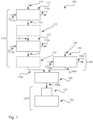
- Figure 1 discloses an arrangement for preparing a gaseous ammonia based fuel to be combusted in a boiler.
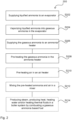
- Figure 2 discloses a flow chart illustrating a method for preparing a gaseous ammonia based fuel to be combusted in a boiler.
Description of Embodiments
-
The present disclosure will now be described more fully hereinafter with reference to the accompanying drawings, in which currently preferred embodiments of the disclosure are shown. This disclosure may, however, be embodied in many different forms and should not be construed as limited to the embodiments set forth herein; rather, these embodiments are provided for thoroughness and completeness, and fully convey the scope of the disclosure to the skilled person. It should also be noted that, although not illustrated, the arrangement may comprise additional valves, control signal transmitters, flow meters, circulation pumps and other similar components according to relevant rules and legislations and normal ship building practice. The provision of such additional components is routine matter for a person skilled in the art and the inclusion of all such components would render the schematic drawings unclear.
-
With reference to figure 1, there is disclosed an arrangement 100 for preparing a gaseous ammonia based fuel to be combusted in a boiler 132. The arrangement 100 comprises an ammonia fuel supply system 110. The ammonia fuel supply system 110 comprises an evaporator 111 and an ammonia heater 112.
-
The evaporator 111 is configured to vaporize liquified ammonia into gaseous ammonia by a first heating medium. The evaporator 111 may be configured to vaporize the liquified ammonia into gaseous ammonia having an evaporator output temperature between -33-50°C. The first heating medium may be chosen from a group consisting of seawater, cooling water from an engine, refrigerator from an air condition system, and thermal fluid from heaters and/or boilers. The evaporator 111 may comprise a first heating medium inlet 111a configured to supply the first heating medium to the evaporator 111. The evaporator 111 may comprise a first heating medium outlet 111b configured to supply the first heating medium from the evaporator 111 after heat has been transferred from the first heating medium to the liquified ammonia.
-
The ammonia heater 112 is arranged after the evaporator 111. The ammonia heater 112 is configured to receive gaseous ammonia from the evaporator 111. The ammonia heater 112 may be configured to pre-heat the gaseous ammonia by a second heating medium. Alternatively, the ammonia heater 112 may be an electrical heater. An electrical heater may e.g. be provided with an electrically resistive heating element through which an electrical current is fed whereby the electrically resistive heating element becomes heated due to the internal electrical resistance of the electrically resistive heating element. The ammonia is fed through the ammonia heater 112 such that it passes by or through the electrically resistive heating element and thereby absorbs heat from the electrically resistive heating element. The ammonia heater 112 may be configured to pre-heat the gaseous ammonia to an ammonia heater output temperature between 100-300°C. The second heating medium may be chosen from a group consisting of steam, thermal fluid, or exhaust gas. The ammonia heater 112 may comprise a second heating medium inlet 112a configured to supply the second heating medium to the ammonia heater 112. The ammonia heater 112 may comprise a second heating medium outlet 112b configured to supply the second heating medium from the ammonia heater 112 after heat has been transferred from the second heating medium to the gaseous ammonia.
-
The ammonia fuel supply system 110 may comprise a gas valve train 113. The gas valve train 113 may be arranged after the evaporator 111. The gas valve train 113 may be arranged directly after the evaporator 111. The gas valve train may be arranged after the ammonia heater 112, which, as previously discussed, is arranged after the evaporator 111. The gas valve train 113 may be configured to control a flow of the gaseous ammonia to be supplied to the boiler 132.
-
The ammonia fuel supply system 110 may comprise a liquified ammonia supply line 114. The liquified ammonia supply line 114 may be connected to a liquified ammonia tank (not illustrated) in which the liquified ammonia may be stored. Thus, the liquified ammonia supply line 114 may supply the liquified ammonia from the liquified ammonia tank to the evaporator 111.
-
The ammonia fuel supply system 110 may comprise a gaseous ammonia supply line 115. The gaseous ammonia supply line 115 may be configured to supply gaseous ammonia from the evaporator 111 to the ammonia heater 112. If the ammonia fuel supply system 110 comprises the gas valve train 113 being arranged before the ammonia heater 112, the gaseous ammonia supply line 115 is configured to supply the gaseous ammonia from the evaporator 111 to the ammonia heater 112 via the gas valve train 113. Thus, the gaseous ammonia supply line 115 is configured to supply the gaseous ammonia from the evaporator 111 to the other components comprised in the ammonia fuel supply system 110.
-
The arrangement 100 may further comprise a mixer 120. The mixer 120 may be arranged after the ammonia fuel supply system 110. The mixer 120 may be configured to receive the pre-heated gaseous ammonia from the ammonia supply system 110. The mixer 120 may be configured to receive air from an air supply system 140. The mixer 120 may be configured to mix the gaseous ammonia and the air and thereby providing the gaseous ammonia based fuel.
-
The ammonia fuel supply system 110 may further comprise an outlet gaseous ammonia supply line 110a. The outlet gaseous ammonia supply line 110a may be connected to the mixer 120 such that the pre-heated gaseous ammonia may be supplied from the ammonia fuel supply system 110 to the mixer 120.
-
The air supply system 140 may be comprised in the arrangement 100. The air supply system 140 may comprise an air heater 142. The air heater 142 may be arranged before the mixer 120. The air heater 142 may be configured to pre-heat the air by the second heating medium or by a third heating medium, preferably by the second heating medium. Alternatively, the air heater 142 may be an electrical heater. An electrical heater may e.g. be provided with an electrically resistive heating element through which an electrical current is fed whereby the electrically resistive heating element becomes heated due to the internal electrical resistance of the electrically resistive heating element. The air may be fed through the air heater 112 such that it passes by or through the electrically resistive heating element and thereby absorbs heat from the electrically resistive heating element. The air heater 142 may further be configured to supply the pre-heated air to the mixer 120. The air heater 142 may be configured to pre-heat the air to an air heater output temperature between 100-400°C. The third heating medium may be chosen from the group consisting of steam, thermal fluid, or exhaust gas. Thus, it should be noted that the second heating medium and the third heating medium may be chosen from groups consisting of the same kinds of heating mediums. The heating medium actually chosen to use to pre-heat the gaseous ammonia may be different from the heating medium actually chosen to use to pre-heat the air. Alternatively, the heating medium actually chosen to use to pre-heat the gaseous ammonia may be the same as the heating medium actually chosen to use to pre-heat the air.
-
The air heater 142 may comprise a heating medium inlet 142a configured to supply the second heating medium or the third heating medium to the air heater 142. The air heater 142 may comprise a heating medium outlet 142b configured to supply the second heating medium or the third heating medium from the air heater 142 after heat has been transferred from the second or third heating medium to the air.
-
The air supply system 140 may comprise an inlet air supply line 144. The inlet air supply line 144 may be configured supply the air to the air supply system 140. The air may be ambient air from outside or may be air from an interior, such as from an engine room. The air supply system 140 may comprise an outlet air supply line 140a. The outlet air supply line 140a may be connected to the mixer 120 such that the air may be supplied from the air supply system 140 to the mixer 120. If the air supply system 140 comprises the air heater 142, the outlet air supply line 140a is configured to supply the pre-heated air from the air supply system 140 to the mixer 120.
-
The arrangement 100 may further comprise a boiler system 130. The boiler system 130 may comprise a burner or furnace 131 and a boiler 132. The boiler system 130 may be configured to receive the gaseous ammonia based fuel from the mixer 120. The boiler system 130 may be configured to combust the gaseous ammonia based fuel to produce steam, to produce heat, to heat water and/or to heat thermal fluids.
-
The arrangement 100 may comprise a gaseous ammonia based fuel supply line 120a. The gaseous ammonia based fuel supply line 120a may be configured to supply the gaseous ammonia based fuel from the mixer 120 to the boiler system 130. If the mixer 120 is excluded from the arrangement 100, the gaseous ammonia based fuel supply line 120a may be configured to supply gaseous ammonia based fuel from the ammonia fuel supply system 110 to the furnace or burner 131 of the boiler system 130.
-
With reference to figure 2, a flow chart illustrating a method 200 for preparing a gaseous ammonia based fuel to be combusted in a furnace or burner 131 of a boiler system 130 is illustrated by way of example.
-
Generally, a first step S202 of the method 200 may be to supply liquified ammonia to an evaporator 111. In a second step S204, the liquified ammonia may be vaporized into gaseous ammonia in the evaporator 111 by a first heating medium. Thereafter, in a third step S206, the gaseous ammonia may be supplied to an ammonia heater 112 from the evaporator 111. In a fourth step S208, the gaseous ammonia may be pre-heated in the ammonia heater by a second heating medium, or by an electrical heater.
-
The method 200 may further comprise, in a fifth step S212, mixing the pre-heated gaseous ammonia and air in a mixer and thereby providing the gaseous ammonia based fuel.
-
The method 200 may further comprise, in a sixth step S210, pre-heating the air in an air heater by the second heating medium or a third heating medium, preferably the second heating medium, or by an electrical heater, before the air being supplied to the mixer. Thus, in such a case, the mixing S212 will be a mixing of pre-heated ammonia and pre-heated air in a mixer 120. It should be noted that the method may comprise the fifth step S212 and that the sixth step S210 concerning pre-heating the air may be omitted. However, if the sixth step S210 is present, it is preferably performed before the fifth step S212 concerning the mixing. However, it is also conceivable to perform the mixing in the fifth step S212 and then performing a heating step similar to the heating step S210 of the mixture of the pre-heated ammonia and the air. It is also conceivable to have a pre-heating step S208 in which the ammonia is pre-heated and a pre-heating step S210 in which the air is pre-heated before the step S212 of mixing followed by an additional step of heating where the mixture from the mixer 120 is additionally heated before being transferred to the boiler system 130.
-
The method 200 may further comprise, in a seventh step S214, producing steam, producing heat, heating water and/or heating thermal fluids in a boiler system 130 by combusting the gaseous ammonia based fuel in a furnace or burner 131 of the boiler system 130.
-
It may in this context be noted that the numbering of the steps from first to seventh step does not refer to that the steps necessarily are to be performed in this specific consecutive order. The numbering first to seventh are primarily intended to be used as labels to facilitate making a distinction when referring to the different steps. The mutual order of the different steps is apparent from the description of the arrangement.
End comments
-
It is contemplated that there are numerous modifications of the embodiments described herein, which are still within the scope of the invention as defined by the appended claims.
-
Additionally, variations to the disclosed embodiments can be understood and effected by the skilled person in practicing the claimed invention, from a study of the drawings, the disclosure, and the appended claims. In the claims, the word "comprising" does not exclude other elements or steps, and the indefinite article "a" or "an" does not exclude a plurality. The mere fact that certain measures are recited in mutually different dependent claims does not indicate that a combination of these measured cannot be used to advantage.