EP4163488A1 - Anordnung zur vorbereitung eines gasförmigen brennstoffs auf ammoniakbasis zur verbrennung in einem kessel und verfahren dafür - Google Patents
Anordnung zur vorbereitung eines gasförmigen brennstoffs auf ammoniakbasis zur verbrennung in einem kessel und verfahren dafür Download PDFInfo
- Publication number
- EP4163488A1 EP4163488A1 EP21201692.7A EP21201692A EP4163488A1 EP 4163488 A1 EP4163488 A1 EP 4163488A1 EP 21201692 A EP21201692 A EP 21201692A EP 4163488 A1 EP4163488 A1 EP 4163488A1
- Authority
- EP
- European Patent Office
- Prior art keywords
- ammonia
- air
- gaseous ammonia
- heating medium
- heater
- Prior art date
- Legal status (The legal status is an assumption and is not a legal conclusion. Google has not performed a legal analysis and makes no representation as to the accuracy of the status listed.)
- Withdrawn
Links
- QGZKDVFQNNGYKY-UHFFFAOYSA-N Ammonia Chemical compound N QGZKDVFQNNGYKY-UHFFFAOYSA-N 0.000 title claims abstract description 635
- 229910021529 ammonia Inorganic materials 0.000 title claims abstract description 316
- 239000000446 fuel Substances 0.000 title claims abstract description 101
- 238000000034 method Methods 0.000 title claims description 26
- 238000010438 heat treatment Methods 0.000 claims abstract description 133
- 239000012530 fluid Substances 0.000 claims description 27
- 238000002156 mixing Methods 0.000 claims description 11
- 230000008016 vaporization Effects 0.000 claims description 8
- 239000000498 cooling water Substances 0.000 claims description 6
- 239000013535 sea water Substances 0.000 claims description 6
- 239000003507 refrigerant Substances 0.000 claims description 5
- 239000008236 heating water Substances 0.000 claims description 3
- XLYOFNOQVPJJNP-UHFFFAOYSA-N water Substances O XLYOFNOQVPJJNP-UHFFFAOYSA-N 0.000 claims description 3
- 239000003570 air Substances 0.000 description 106
- 239000007789 gas Substances 0.000 description 35
- 239000000203 mixture Substances 0.000 description 7
- 239000007788 liquid Substances 0.000 description 5
- 238000009834 vaporization Methods 0.000 description 5
- CURLTUGMZLYLDI-UHFFFAOYSA-N Carbon dioxide Chemical compound O=C=O CURLTUGMZLYLDI-UHFFFAOYSA-N 0.000 description 4
- 238000009835 boiling Methods 0.000 description 4
- 238000002485 combustion reaction Methods 0.000 description 4
- OKKJLVBELUTLKV-UHFFFAOYSA-N Methanol Chemical compound OC OKKJLVBELUTLKV-UHFFFAOYSA-N 0.000 description 3
- 230000008901 benefit Effects 0.000 description 3
- 229910002092 carbon dioxide Inorganic materials 0.000 description 3
- 239000001569 carbon dioxide Substances 0.000 description 3
- 239000012080 ambient air Substances 0.000 description 2
- 230000001419 dependent effect Effects 0.000 description 2
- VNWKTOKETHGBQD-UHFFFAOYSA-N methane Chemical compound C VNWKTOKETHGBQD-UHFFFAOYSA-N 0.000 description 2
- 238000003915 air pollution Methods 0.000 description 1
- 239000002551 biofuel Substances 0.000 description 1
- 230000000295 complement effect Effects 0.000 description 1
- 239000002826 coolant Substances 0.000 description 1
- 238000001816 cooling Methods 0.000 description 1
- 230000003247 decreasing effect Effects 0.000 description 1
- 238000005553 drilling Methods 0.000 description 1
- 230000007613 environmental effect Effects 0.000 description 1
- 239000005431 greenhouse gas Substances 0.000 description 1
- 239000008240 homogeneous mixture Substances 0.000 description 1
- -1 hydrogen Chemical compound 0.000 description 1
- 229910052739 hydrogen Inorganic materials 0.000 description 1
- 239000001257 hydrogen Substances 0.000 description 1
- 238000004519 manufacturing process Methods 0.000 description 1
- 239000000463 material Substances 0.000 description 1
- 238000012986 modification Methods 0.000 description 1
- 230000004048 modification Effects 0.000 description 1
- 230000002265 prevention Effects 0.000 description 1
- 230000008569 process Effects 0.000 description 1
- 239000000376 reactant Substances 0.000 description 1
- 238000005057 refrigeration Methods 0.000 description 1
- 230000009466 transformation Effects 0.000 description 1
- 230000007704 transition Effects 0.000 description 1
- 239000002918 waste heat Substances 0.000 description 1
Images
Classifications
-
- F—MECHANICAL ENGINEERING; LIGHTING; HEATING; WEAPONS; BLASTING
- F02—COMBUSTION ENGINES; HOT-GAS OR COMBUSTION-PRODUCT ENGINE PLANTS
- F02M—SUPPLYING COMBUSTION ENGINES IN GENERAL WITH COMBUSTIBLE MIXTURES OR CONSTITUENTS THEREOF
- F02M21/00—Apparatus for supplying engines with non-liquid fuels, e.g. gaseous fuels stored in liquid form
- F02M21/02—Apparatus for supplying engines with non-liquid fuels, e.g. gaseous fuels stored in liquid form for gaseous fuels
- F02M21/0203—Apparatus for supplying engines with non-liquid fuels, e.g. gaseous fuels stored in liquid form for gaseous fuels characterised by the type of gaseous fuel
- F02M21/0206—Non-hydrocarbon fuels, e.g. hydrogen, ammonia or carbon monoxide
-
- F—MECHANICAL ENGINEERING; LIGHTING; HEATING; WEAPONS; BLASTING
- F02—COMBUSTION ENGINES; HOT-GAS OR COMBUSTION-PRODUCT ENGINE PLANTS
- F02M—SUPPLYING COMBUSTION ENGINES IN GENERAL WITH COMBUSTIBLE MIXTURES OR CONSTITUENTS THEREOF
- F02M21/00—Apparatus for supplying engines with non-liquid fuels, e.g. gaseous fuels stored in liquid form
- F02M21/02—Apparatus for supplying engines with non-liquid fuels, e.g. gaseous fuels stored in liquid form for gaseous fuels
- F02M21/0218—Details on the gaseous fuel supply system, e.g. tanks, valves, pipes, pumps, rails, injectors or mixers
- F02M21/0287—Details on the gaseous fuel supply system, e.g. tanks, valves, pipes, pumps, rails, injectors or mixers characterised by the transition from liquid to gaseous phase ; Injection in liquid phase; Cooling and low temperature storage
-
- F—MECHANICAL ENGINEERING; LIGHTING; HEATING; WEAPONS; BLASTING
- F02—COMBUSTION ENGINES; HOT-GAS OR COMBUSTION-PRODUCT ENGINE PLANTS
- F02M—SUPPLYING COMBUSTION ENGINES IN GENERAL WITH COMBUSTIBLE MIXTURES OR CONSTITUENTS THEREOF
- F02M21/00—Apparatus for supplying engines with non-liquid fuels, e.g. gaseous fuels stored in liquid form
- F02M21/02—Apparatus for supplying engines with non-liquid fuels, e.g. gaseous fuels stored in liquid form for gaseous fuels
- F02M21/06—Apparatus for de-liquefying, e.g. by heating
-
- F—MECHANICAL ENGINEERING; LIGHTING; HEATING; WEAPONS; BLASTING
- F23—COMBUSTION APPARATUS; COMBUSTION PROCESSES
- F23D—BURNERS
- F23D11/00—Burners using a direct spraying action of liquid droplets or vaporised liquid into the combustion space
- F23D11/36—Details, e.g. burner cooling means, noise reduction means
- F23D11/40—Mixing tubes or chambers; Burner heads
-
- F—MECHANICAL ENGINEERING; LIGHTING; HEATING; WEAPONS; BLASTING
- F23—COMBUSTION APPARATUS; COMBUSTION PROCESSES
- F23D—BURNERS
- F23D11/00—Burners using a direct spraying action of liquid droplets or vaporised liquid into the combustion space
- F23D11/36—Details, e.g. burner cooling means, noise reduction means
- F23D11/44—Preheating devices; Vaporising devices
-
- F—MECHANICAL ENGINEERING; LIGHTING; HEATING; WEAPONS; BLASTING
- F23—COMBUSTION APPARATUS; COMBUSTION PROCESSES
- F23K—FEEDING FUEL TO COMBUSTION APPARATUS
- F23K5/00—Feeding or distributing other fuel to combustion apparatus
- F23K5/02—Liquid fuel
- F23K5/14—Details thereof
- F23K5/22—Vaporising devices
-
- F—MECHANICAL ENGINEERING; LIGHTING; HEATING; WEAPONS; BLASTING
- F23—COMBUSTION APPARATUS; COMBUSTION PROCESSES
- F23L—SUPPLYING AIR OR NON-COMBUSTIBLE LIQUIDS OR GASES TO COMBUSTION APPARATUS IN GENERAL ; VALVES OR DAMPERS SPECIALLY ADAPTED FOR CONTROLLING AIR SUPPLY OR DRAUGHT IN COMBUSTION APPARATUS; INDUCING DRAUGHT IN COMBUSTION APPARATUS; TOPS FOR CHIMNEYS OR VENTILATING SHAFTS; TERMINALS FOR FLUES
- F23L15/00—Heating of air supplied for combustion
-
- F—MECHANICAL ENGINEERING; LIGHTING; HEATING; WEAPONS; BLASTING
- F23—COMBUSTION APPARATUS; COMBUSTION PROCESSES
- F23K—FEEDING FUEL TO COMBUSTION APPARATUS
- F23K2300/00—Pretreatment and supply of liquid fuel
- F23K2300/20—Supply line arrangements
- F23K2300/205—Vaporising
Definitions
- the invention relates to an arrangement for preparing a gaseous ammonia based fuel to be combusted in a boiler.
- the invention also relates to a method for preparing a gaseous ammonia based fuel to be combusted in a boiler.
- Marine engines powered by oil or gas are well known in the art.
- Oil and gas fired boilers for marine steam production are also well known in the art.
- the choice of fuel for the boiler operation is made in relation to the fuels selected for the marine engine operation.
- the marine engine is powered by oil
- the boiler is often powered by oil as well.
- the marine engine and the boiler may be powered by different fuels.
- JP2020183854 A discloses a heat engine which uses ammonia as main fuel, wherein liquified ammonia is evaporated in an evaporator before being supplied to the engine. It further discloses that the cold generated from the evaporator is supplied to a cooler by a cooling medium to enable external refrigeration and cooling.
- the prior art does not disclose an environmentally friendly marine arrangement which adequately addresses the set of design criteria of improving the flammability of the alternative fuel as well as keeping the ignited alternative fuel as a stable burning flame, and especially the prior art does not disclose how to provide an overall arrangement which may be used in a convenient manner over time when it comes to meeting said set of design criteria.
- an ammonia fuel supply system comprising:
- gaseous ammonia based fuel is herein meant a gaseous fuel which comprises ammonia.
- the gaseous ammonia based fuel may comprise only gaseous ammonia.
- the gaseous ammonia based fuel may also comprise other gaseous fuels.
- the gaseous ammonia based fuel may also comprise air.
- the gaseous ammonia based fuel is a gaseous fuel in which at least a part of the gaseous fuel is gaseous ammonia.
- the amount of ammonia comprised in the gaseous ammonia based fuel may depend on the boiler in which the gaseous ammonia based fuel will be combusted.
- the ammonia is stored as liquified ammonia since the liquified ammonia takes less space compared to gaseous ammonia and thereby less storage space is needed.
- the furnace or burner of the boiler system is designed to combust the ammonia based fuel in gaseous form, the liquified ammonia has to be transformed into gaseous ammonia before being supplied to the boiler.
- the evaporator is a heat exchanger configured to vaporize the liquified ammonia.
- the heat exchanger may be e.g. a plate heat exchanger, or a shell and tube heat exchanger.
- the evaporator may be a boiler configured to vaporize the liquified ammonia.
- the evaporator is designed in a resistant material which is able to handle liquified ammonia and gaseous ammonia.
- the possibilities of igniting the ammonia and to keep the ammonia as a stable burning flame is crucial parameters for the boiler, since the power output of the boiler will be almost proportional to both a heating value and a flame velocity of the ammonia.
- the heating value is referring to energy content in the ammonia and this cannot be changed.
- both liquified ammonia and gaseous ammonia have the same heating value of 18.6 MJ/kg.
- the flame velocity describes the speed at which a flame will propagate through a quiescent, homogenous mixture of unburned reactants. Thus, basically, it is a number describing how fast a certain fuel may burn. The flame velocity may be improved.
- Liquified ammonia is in scientific sources typically said to have a flame velocity of 0.010 - 0.020 m/s, and best estimates are often said to be about 0.014 - 0.016 m/s.
- Gaseous ammonia is in scientific sources typically said to have a flame velocity of 0.03 - 0.13 m/s, and best estimates are often said to be about 0.07 - 0.09 m/s. The actual values vary dependent upon the actual situation and different scientific sources may therefore indicate different values.
- the flame velocity increases. This increase is from approximately 0.015 m/s to approximately 0.08 m/s. Moreover, the flame velocity may be further increased with an increased temperature of the gaseous ammonia.
- the evaporator is advantageous in that both the ammonia may be stored as liquified ammonia but also to improve the flame velocity of the ammonia.
- the temperature of the gaseous ammonia may be further increased and thereby also the flame velocity of the gaseous ammonia.
- the ammonia heater is a high temperature heat source configured to pre-heat the gaseous ammonia.
- a flame ignition range, in which the ammonia becomes flammable may be increased as well.
- the flammability of the gaseous ammonia may be improved.
- By increasing and improving the flammability of the gaseous ammonia means for burning more ammonia in the boiler faster may be provided.
- the flame velocity and the flame ignition range of the ammonia may be increased.
- the flammability enhancement of the ammonia is increased and improved.
- a more efficient and flammable fuel to be combusted in the boiler is achieved.
- the term "after” may, but does not necessarily need to, mean that the ammonia heater is physically located after the evaporator. After is primarily intended to refer to a position as seen along the flow path of the ammonia.
- the ammonia heater is located after the evaporator as seen along the flow of the ammonia since the ammonia supplied to the ammonia heater is gaseous ammonia which has already passed the evaporator. If the ammonia heater is a module being physically separate from the evaporator, the ammonia heater may e.g. be located side by side with the evaporator.
- the vaporization involves the provision of a significant amount energy to transfer the ammonia from liquid form to gaseous form, but the heating medium supplying this energy does not necessarily have to be a high temperature medium; it is basically sufficient that it is slightly above the vaporization temperature for the ammonia, or alternatively slightly above the desired output temperature of the gaseous ammonia from the evaporator. Preferred embodiments concerning the vaporization appear below.
- the pre-heating of the gaseous ammonia in the ammonia heater does not involve a phase transition and the heat provided by the second heating medium will mostly go directly to a raise in the temperature of the gaseous ammonia.
- a sufficiently high temperature on the heating medium is of more importance compared to in the vaporization step.
- the arrangement may further comprise a mixer being arranged after the ammonia fuel supply system and being configured to receive the pre-heated gaseous ammonia from the ammonia fuel supply system, to receive air from an air supply system, and to mix the pre-heated gaseous ammonia and the air, and thereby provide the gaseous ammonia based fuel.
- a mixer being arranged after the ammonia fuel supply system and being configured to receive the pre-heated gaseous ammonia from the ammonia fuel supply system, to receive air from an air supply system, and to mix the pre-heated gaseous ammonia and the air, and thereby provide the gaseous ammonia based fuel.
- the gaseous ammonia is supplied to the mixer via an outlet gaseous ammonia supply line from the ammonia fuel supply system.
- the air is preferably supplied to the mixer via an outlet air supply line from the air supply system.
- the gaseous ammonia and the air are separately supplied to the mixer and are mixed together in the mixer.
- This is advantageous in that it facilitates to separately control the supply of gaseous ammonia and the air.
- it is facilitated to separately control e.g. the flow of the gaseous ammonia respectively the flow of the air.
- the gaseous ammonia based fuel comprising a desired amount of gaseous ammonia and air, respectively.
- backfire prevention may be ensured by having sufficiently high flow velocity in feed pipes being arranged after the mixer.
- the flow velocity of the flammable mixture should be higher than the highest flame velocity at the present conditions. With the conditions discussed in this disclosure it is considered that the flow velocity should be higher than 0,08m/s. However, it may be noted that if e.g. the temperature is increased, the flame velocity increases and consequently the system should be designed such that the flow velocity still remains higher than the flame velocity.
- the air supply system may comprise an air heater being arranged before the mixer, and being configured to pre-heat the air by the second heating medium or by a third heating medium, preferably by the second heating medium, or by an electrical heater, and to supply the pre-heated air to the mixer.
- the air may be ambient air from outside, or from an interior room in which the air system and or boiler is located, such as e.g. an engine room of a land-based industry facility or an engine room of a marine vessel.
- the air heater is basically configured to pre-heat the air to as high temperature as practically is possible before supplying the pre-heated air to the mixer.
- the air heater is a high temperature heat source configured to pre-heat the air.
- the flammability of the gaseous ammonia based fuel may be improved.
- means for burning more fuels in the boiler faster may be provided.
- gaseous ammonia based fuel has a temperature of 25°C, a flame ignition range of 16-28% of the gaseous ammonia based fuel is flammable. If the gaseous ammonia based fuel has a temperature of 300°C, a flame ignition range of 13-34% of the gaseous ammonia based fuel is flammable. If the gaseous ammonia based fuel has a temperature of 400°C, a flame ignition range of 11-37% of the gaseous ammonia based fuel is flammable.
- the provision of having a flexible arrangement is provided.
- the airflow may be approximately about four to five times, based on a molar flow, higher than the gaseous ammonia airflow, thus ensuring more available heated air in the overall combustion process.
- the term "before” may, but does not necessarily need to, mean that the air heater is physically located before the mixer. Before is primarily intended to refer to a position as seen along the flow path of the air.
- the air heater is located before the mixer as seen along the flow of the air since the air supplied to the mixer is air which has already passed the air heater. If the air heater is a module being physically separate from the mixer, the air heater may e.g. be located side by side with the mixer.
- the evaporator may be configured to vaporize the liquified ammonia into gaseous ammonia to an evaporator output temperature between -33 °C and +50°C.
- the evaporator output temperature depends on a temperature of the liquified ammonia as well as a temperature of the first heating medium.
- the temperature of the first heating medium may be varied depending on a desired evaporator output temperature.
- the liquified ammonia may have a temperature which is slightly below -33°C when being supplied to the evaporator.
- the boiling point of ammonia is -33°C at normal atmospheric pressure and as the ammonia is stored in liquid state, the temperature of the liquid ammonia should be slightly below -33°C.
- the liquid ammonia may be stored under pressure.
- the temperature requirements of the evaporator may be relatively moderate since the liquified ammonia will vaporize when the temperature of the ammonia is above the boiling point -33°C.
- moderate requirements it is herein meant that it is not necessary to make use of a heating medium with really high temperature as the ammonia has a rather low boiling point.
- a requirement for the heating medium is that the heating medium should be able to transfer heat to the liquified ammonia such that the liquified ammonia will vaporize.
- the evaporator output temperature is preferably between -33°C and +50°C.
- the first heating medium is chosen from a group consisting of seawater, cooling water from an engine, refrigerant from an air condition system, and thermal fluid from heaters and/or boilers.
- the first heating medium may have as high temperature as practically possible such that the vaporized ammonia may have as high temperature as practically possible.
- the first heating medium should have a temperature such that the liquified ammonia will vaporize. Therefore, seawater, cooling water from the engine, refrigerant from an air condition system, or thermal fluid from heaters and/or boilers may be just fine as heating medium, as the temperature of the first heating medium just has to be above the boiling point of the ammonia, but preferably higher.
- the thermal fluid from heaters and/or boilers typically refers to thermal fluid by which waste heat from the heater or boiler is transferred to the ammonia. It may e.g.
- the evaporator may be a liquid to liquid type, a gas to gas type or a liquid to gas type. Which type evaporator to choose depends typically on which gives the best techno-economic performance taking into account both the arrangement as such and also neighboring systems; especially the neighboring systems supplying heating mediums, of the industry facility or marine vessel.
- the first heating medium may be seawater in case the arrangement is positioned at the sea, e.g. on a ship, or in vicinity of the sea such that the seawater is easy to supply to the arrangement as the first heating medium.
- the first heating medium may be cooling water from an engine or refrigerant form the air condition system.
- the first medium may be thermal fluid from heaters and/or boilers.
- the engine or air condition system should preferably be arranged in vicinity to the arrangement such that the cooling water or refrigerant is easy to supply to the arrangement. This is advantageous in that no extra medium needs to be supplied to the arrangement, or to the vicinity of the arrangement, in order to being able to vaporize the liquified ammonia.
- the ammonia heater may be configured to pre-heat the gaseous ammonia to an ammonia heater output temperature between 100°C and 300°C.
- the ammonia heater output temperature depends on a temperature of the gaseous ammonia and on a temperature of the second heating medium.
- the temperature of the second heating medium may be varied depending on a desired ammonia heater output temperature. It is considered that an ammonia heater output temperature above 300°C begins to set requirements on the temperature and flow of the second heating medium which could make the arrangement counter-productive in that the additional effort to increase the ammonia heater output temperature above 300°C becomes too cumbersome compared to the advantage achieved in the boiler function.
- the second heating medium is chosen from a group consisting of steam, thermal fluid, or exhaust gas.
- the second heating medium has as high temperature as practically possible such that the pre-heated gaseous ammonia will have as high temperature as practically possible.
- the steam may originate from a boiler economizer.
- the exhaust gas may be exhaust gas originating from a main engine and/or an auxiliary engine.
- the second heating medium has a temperature between 100°C and 400°C.
- the ammonia heater is configured to direct the steam, the exhaust gas, or the thermal fluid such that heat is transferred to the gaseous ammonia.
- the ammonia heater may be a gas/gas heater type, a fluid/gas heater type, or a steam/gas heater type.
- the boiler economizer, the main engine or the auxiliary engine should be comprised in the arrangement or arranged in vicinity to the arrangement. This is advantageous in that no extra medium needs to be supplied to the arrangement, or to the vicinity of the arrangement, in order to being able to pre-heat the gaseous ammonia.
- the air heater may be configured to pre-heat the air to an air heater output temperature between 100°C and 400°C.
- the air heater output temperature depends on a temperature of the air and on a temperature of the second heating medium or the third heating medium.
- the temperature of the second heating medium or the third heating medium may be varied depending on a desired air heater output temperature.
- the pre-heated gaseous ammonia and the pre-heated air should be pre-heated to similar temperatures. This is advantageous in that the mixing of the gaseous ammonia and air may be more efficient if the temperature of the respective gas is similar. Thus, an improved mixing process may be achieved.
- the temperatures are considered to be similar if the temperature difference is less than 50°C.
- the third heating medium may be chosen from a group consisting of steam, thermal fluid, or exhaust gas.
- the third heating medium has as high temperature as practically possible such that the pre-heated gaseous ammonia will have as high temperature as practically possible.
- the steam may originate from a boiler economizer.
- the exhaust gas may be direct exhaust gas originating from a main engine and/or an auxiliary engine.
- the third heating medium has a temperature between 100°C and 400°C.
- the ammonia heater is configured to direct the steam, the exhaust gas, or the thermal fluid such that heat is transferred to the gaseous ammonia.
- the ammonia heater may be a gas/gas heater type, a fluid/gas heater type, or a steam/gas heater type.
- the boiler economizer, the main engine or the auxiliary engine should be comprised in the arrangement or arranged in vicinity to the arrangement. This is advantageous in that no extra medium needs to be supplied to the arrangement, or to the vicinity of the arrangement, in order to being able to pre-heat the gaseous ammonia.
- the second heating medium and the third heating medium may be chosen from groups consisting of the same kinds of heating mediums, different heating medium may be chosen as the second heating medium respectively as the third heating medium. However, the same heating medium may be chosen as both the second heating medium and the third heating medium.
- the ammonia fuel supply system may further comprise a gas valve train being arranged after the evaporator and being configured to control a flow of the gaseous ammonia to be supplied to the furnace or burner of the boiler system.
- the gas valve train may be arranged before the ammonia heater or after the ammonia heater.
- the gas valve train may be configured to control the flow of the gaseous ammonia or of the pre-heated gaseous ammonia.
- the arrangement may further comprise a boiler system being configured to receive and combust the gaseous ammonia based fuel to produce steam, to produce heat, to heat water and/or to heat thermal fluids.
- a boiler system being configured to receive and combust the gaseous ammonia based fuel to produce steam, to produce heat, to heat water and/or to heat thermal fluids.
- the above mentioned object has also been achieved in accordance with a method for preparing a gaseous ammonia based fuel to be combusted, preferably be combusted in a furnace or burner of a boiler system, the method comprising: supplying liquified ammonia to an evaporator, vaporizing the liquified ammonia into gaseous ammonia in the evaporator by a first heating medium, supplying the gaseous ammonia to an ammonia heater from the evaporator, and pre-heating the gaseous ammonia in the ammonia heater by a second heating medium.
- the method may further comprise mixing the pre-heated gaseous ammonia and air in a mixer and thereby providing the gaseous ammonia based fuel.
- the method may further comprise pre-heating the air in an air heater by the second heating medium or a third heating medium, preferably the second heating medium, or by an electrical heater, before the pre-heated air being supplied to the mixer.
- the method may further comprise producing steam, producing heat, heating water and/or heating thermal fluids in a boiler system by combusting the gaseous ammonia based fuel in a furnace or burner of the boiler system.
- the arrangement is preferably placed onboard a marine vessel, such as a ship.
- the method is preferably performed onboard a marine vessel, such as a ship.
- neither the arrangement, nor the method is limited to be used onboard a ship. This may e.g. be the case, apart from ships, in other marine applications. It may e.g. be platforms, such as platforms of the kind used for drilling for oil or gas.
- the arrangement and method may also be useful for land-based applications.
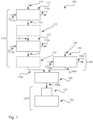
- the arrangement 100 comprises an ammonia fuel supply system 110.
- the ammonia fuel supply system 110 comprises an evaporator 111 and an ammonia heater 112.
- the evaporator 111 is configured to vaporize liquified ammonia into gaseous ammonia by a first heating medium.
- the evaporator 111 may be configured to vaporize the liquified ammonia into gaseous ammonia having an evaporator output temperature between -33-50°C.
- the first heating medium may be chosen from a group consisting of seawater, cooling water from an engine, refrigerator from an air condition system, and thermal fluid from heaters and/or boilers.
- the evaporator 111 may comprise a first heating medium inlet 111a configured to supply the first heating medium to the evaporator 111.
- the evaporator 111 may comprise a first heating medium outlet 111b configured to supply the first heating medium from the evaporator 111 after heat has been transferred from the first heating medium to the liquified ammonia.
- the ammonia heater 112 is arranged after the evaporator 111.
- the ammonia heater 112 is configured to receive gaseous ammonia from the evaporator 111.
- the ammonia heater 112 may be configured to pre-heat the gaseous ammonia by a second heating medium.
- the ammonia heater 112 may be an electrical heater.
- An electrical heater may e.g. be provided with an electrically resistive heating element through which an electrical current is fed whereby the electrically resistive heating element becomes heated due to the internal electrical resistance of the electrically resistive heating element.
- the ammonia is fed through the ammonia heater 112 such that it passes by or through the electrically resistive heating element and thereby absorbs heat from the electrically resistive heating element.
- the ammonia heater 112 may be configured to pre-heat the gaseous ammonia to an ammonia heater output temperature between 100-300°C.
- the second heating medium may be chosen from a group consisting of steam, thermal fluid, or exhaust gas.
- the ammonia heater 112 may comprise a second heating medium inlet 112a configured to supply the second heating medium to the ammonia heater 112.
- the ammonia heater 112 may comprise a second heating medium outlet 112b configured to supply the second heating medium from the ammonia heater 112 after heat has been transferred from the second heating medium to the gaseous ammonia.
- the ammonia fuel supply system 110 may comprise a gas valve train 113.
- the gas valve train 113 may be arranged after the evaporator 111.
- the gas valve train 113 may be arranged directly after the evaporator 111.
- the gas valve train may be arranged after the ammonia heater 112, which, as previously discussed, is arranged after the evaporator 111.
- the gas valve train 113 may be configured to control a flow of the gaseous ammonia to be supplied to the boiler 132.
- the ammonia fuel supply system 110 may comprise a liquified ammonia supply line 114.
- the liquified ammonia supply line 114 may be connected to a liquified ammonia tank (not illustrated) in which the liquified ammonia may be stored.
- the liquified ammonia supply line 114 may supply the liquified ammonia from the liquified ammonia tank to the evaporator 111.
- the ammonia fuel supply system 110 may comprise a gaseous ammonia supply line 115.
- the gaseous ammonia supply line 115 may be configured to supply gaseous ammonia from the evaporator 111 to the ammonia heater 112. If the ammonia fuel supply system 110 comprises the gas valve train 113 being arranged before the ammonia heater 112, the gaseous ammonia supply line 115 is configured to supply the gaseous ammonia from the evaporator 111 to the ammonia heater 112 via the gas valve train 113. Thus, the gaseous ammonia supply line 115 is configured to supply the gaseous ammonia from the evaporator 111 to the other components comprised in the ammonia fuel supply system 110.
- the arrangement 100 may further comprise a mixer 120.
- the mixer 120 may be arranged after the ammonia fuel supply system 110.
- the mixer 120 may be configured to receive the pre-heated gaseous ammonia from the ammonia supply system 110.
- the mixer 120 may be configured to receive air from an air supply system 140.
- the mixer 120 may be configured to mix the gaseous ammonia and the air and thereby providing the gaseous ammonia based fuel.
- the ammonia fuel supply system 110 may further comprise an outlet gaseous ammonia supply line 110a.
- the outlet gaseous ammonia supply line 110a may be connected to the mixer 120 such that the pre-heated gaseous ammonia may be supplied from the ammonia fuel supply system 110 to the mixer 120.
- the air supply system 140 may be comprised in the arrangement 100.
- the air supply system 140 may comprise an air heater 142.
- the air heater 142 may be arranged before the mixer 120.
- the air heater 142 may be configured to pre-heat the air by the second heating medium or by a third heating medium, preferably by the second heating medium.
- the air heater 142 may be an electrical heater.
- An electrical heater may e.g. be provided with an electrically resistive heating element through which an electrical current is fed whereby the electrically resistive heating element becomes heated due to the internal electrical resistance of the electrically resistive heating element.
- the air may be fed through the air heater 112 such that it passes by or through the electrically resistive heating element and thereby absorbs heat from the electrically resistive heating element.
- the air heater 142 may further be configured to supply the pre-heated air to the mixer 120.
- the air heater 142 may be configured to pre-heat the air to an air heater output temperature between 100-400°C.
- the third heating medium may be chosen from the group consisting of steam, thermal fluid, or exhaust gas.
- the second heating medium and the third heating medium may be chosen from groups consisting of the same kinds of heating mediums.
- the heating medium actually chosen to use to pre-heat the gaseous ammonia may be different from the heating medium actually chosen to use to pre-heat the air.
- the heating medium actually chosen to use to pre-heat the gaseous ammonia may be the same as the heating medium actually chosen to use to pre-heat the air.
- the air heater 142 may comprise a heating medium inlet 142a configured to supply the second heating medium or the third heating medium to the air heater 142.
- the air heater 142 may comprise a heating medium outlet 142b configured to supply the second heating medium or the third heating medium from the air heater 142 after heat has been transferred from the second or third heating medium to the air.
- the air supply system 140 may comprise an inlet air supply line 144.
- the inlet air supply line 144 may be configured supply the air to the air supply system 140.
- the air may be ambient air from outside or may be air from an interior, such as from an engine room.
- the air supply system 140 may comprise an outlet air supply line 140a.
- the outlet air supply line 140a may be connected to the mixer 120 such that the air may be supplied from the air supply system 140 to the mixer 120. If the air supply system 140 comprises the air heater 142, the outlet air supply line 140a is configured to supply the pre-heated air from the air supply system 140 to the mixer 120.
- the arrangement 100 may further comprise a boiler system 130.
- the boiler system 130 may comprise a burner or furnace 131 and a boiler 132.
- the boiler system 130 may be configured to receive the gaseous ammonia based fuel from the mixer 120.
- the boiler system 130 may be configured to combust the gaseous ammonia based fuel to produce steam, to produce heat, to heat water and/or to heat thermal fluids.
- the arrangement 100 may comprise a gaseous ammonia based fuel supply line 120a.
- the gaseous ammonia based fuel supply line 120a may be configured to supply the gaseous ammonia based fuel from the mixer 120 to the boiler system 130. If the mixer 120 is excluded from the arrangement 100, the gaseous ammonia based fuel supply line 120a may be configured to supply gaseous ammonia based fuel from the ammonia fuel supply system 110 to the furnace or burner 131 of the boiler system 130.
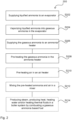
- FIG. 2 a flow chart illustrating a method 200 for preparing a gaseous ammonia based fuel to be combusted in a furnace or burner 131 of a boiler system 130 is illustrated by way of example.
- a first step S202 of the method 200 may be to supply liquified ammonia to an evaporator 111.
- the liquified ammonia may be vaporized into gaseous ammonia in the evaporator 111 by a first heating medium.
- the gaseous ammonia may be supplied to an ammonia heater 112 from the evaporator 111.
- the gaseous ammonia may be pre-heated in the ammonia heater by a second heating medium, or by an electrical heater.
- the method 200 may further comprise, in a fifth step S212, mixing the pre-heated gaseous ammonia and air in a mixer and thereby providing the gaseous ammonia based fuel.
- the method 200 may further comprise, in a sixth step S210, pre-heating the air in an air heater by the second heating medium or a third heating medium, preferably the second heating medium, or by an electrical heater, before the air being supplied to the mixer.
- the mixing S212 will be a mixing of pre-heated ammonia and pre-heated air in a mixer 120.
- the method may comprise the fifth step S212 and that the sixth step S210 concerning pre-heating the air may be omitted. However, if the sixth step S210 is present, it is preferably performed before the fifth step S212 concerning the mixing.
- the method 200 may further comprise, in a seventh step S214, producing steam, producing heat, heating water and/or heating thermal fluids in a boiler system 130 by combusting the gaseous ammonia based fuel in a furnace or burner 131 of the boiler system 130.
- first to seventh step does not refer to that the steps necessarily are to be performed in this specific consecutive order.
- the numbering first to seventh are primarily intended to be used as labels to facilitate making a distinction when referring to the different steps. The mutual order of the different steps is apparent from the description of the arrangement.
Priority Applications (2)
| Application Number | Priority Date | Filing Date | Title |
|---|---|---|---|
| EP21201692.7A EP4163488A1 (de) | 2021-10-08 | 2021-10-08 | Anordnung zur vorbereitung eines gasförmigen brennstoffs auf ammoniakbasis zur verbrennung in einem kessel und verfahren dafür |
| PCT/EP2022/075926 WO2023057196A1 (en) | 2021-10-08 | 2022-09-19 | An arrangement for preparing a gaseous ammonia based fuel to be combusted in a boiler and a method thereof |
Applications Claiming Priority (1)
| Application Number | Priority Date | Filing Date | Title |
|---|---|---|---|
| EP21201692.7A EP4163488A1 (de) | 2021-10-08 | 2021-10-08 | Anordnung zur vorbereitung eines gasförmigen brennstoffs auf ammoniakbasis zur verbrennung in einem kessel und verfahren dafür |
Publications (1)
| Publication Number | Publication Date |
|---|---|
| EP4163488A1 true EP4163488A1 (de) | 2023-04-12 |
Family
ID=78413600
Family Applications (1)
| Application Number | Title | Priority Date | Filing Date |
|---|---|---|---|
| EP21201692.7A Withdrawn EP4163488A1 (de) | 2021-10-08 | 2021-10-08 | Anordnung zur vorbereitung eines gasförmigen brennstoffs auf ammoniakbasis zur verbrennung in einem kessel und verfahren dafür |
Country Status (2)
| Country | Link |
|---|---|
| EP (1) | EP4163488A1 (de) |
| WO (1) | WO2023057196A1 (de) |
Citations (5)
| Publication number | Priority date | Publication date | Assignee | Title |
|---|---|---|---|---|
| US20120299306A1 (en) * | 2011-05-25 | 2012-11-29 | Denso Corporation | Cogeneration system |
| EP3578767A1 (de) * | 2017-01-31 | 2019-12-11 | IHI Corporation | Wärmezykluseinrichtung |
| CN111330446A (zh) * | 2020-03-27 | 2020-06-26 | 大连船舶重工集团有限公司 | 一种新型船舶尾气处理系统 |
| JP2020183854A (ja) | 2019-05-07 | 2020-11-12 | 中村 徳彦 | 燃料蒸発冷却機能付き熱機関を持つコージェネ発電 |
| CN113294801A (zh) * | 2021-05-26 | 2021-08-24 | 华中科技大学 | 一种可实现纯氨高效清洁燃烧的燃烧装置及其控制方法 |
Family Cites Families (1)
| Publication number | Priority date | Publication date | Assignee | Title |
|---|---|---|---|---|
| DE10011335A1 (de) * | 2000-03-10 | 2001-09-20 | Krupp Uhde Gmbh | Verfahren zur Herstellung von Salpetersäure |
-
2021
- 2021-10-08 EP EP21201692.7A patent/EP4163488A1/de not_active Withdrawn
-
2022
- 2022-09-19 WO PCT/EP2022/075926 patent/WO2023057196A1/en unknown
Patent Citations (5)
| Publication number | Priority date | Publication date | Assignee | Title |
|---|---|---|---|---|
| US20120299306A1 (en) * | 2011-05-25 | 2012-11-29 | Denso Corporation | Cogeneration system |
| EP3578767A1 (de) * | 2017-01-31 | 2019-12-11 | IHI Corporation | Wärmezykluseinrichtung |
| JP2020183854A (ja) | 2019-05-07 | 2020-11-12 | 中村 徳彦 | 燃料蒸発冷却機能付き熱機関を持つコージェネ発電 |
| CN111330446A (zh) * | 2020-03-27 | 2020-06-26 | 大连船舶重工集团有限公司 | 一种新型船舶尾气处理系统 |
| CN113294801A (zh) * | 2021-05-26 | 2021-08-24 | 华中科技大学 | 一种可实现纯氨高效清洁燃烧的燃烧装置及其控制方法 |
Also Published As
| Publication number | Publication date |
|---|---|
| WO2023057196A1 (en) | 2023-04-13 |
Similar Documents
| Publication | Publication Date | Title |
|---|---|---|
| CA1230788A (en) | High efficiency internal combustion steam engine | |
| EP1809947B1 (de) | Verbrennungsofen für siededampf | |
| US3779212A (en) | Non-polluting steam generator system | |
| US4282835A (en) | Internal combustion engine with gas synthesizer | |
| US6526754B1 (en) | Combined cycle power plant | |
| US6736118B1 (en) | Fuel density reduction method and device to improve the ratio of oxygen mass versus fuel mass during ignition in combustion mechanisms operating with fluid hydrocarbon fuels | |
| EP4163488A1 (de) | Anordnung zur vorbereitung eines gasförmigen brennstoffs auf ammoniakbasis zur verbrennung in einem kessel und verfahren dafür | |
| US20160010800A1 (en) | Liquid Natural Gas Vaporization | |
| KR102610291B1 (ko) | 친환경 선박의 연료 공급 시스템 및 이를 포함하는 선박 | |
| CN117222844A (zh) | 双层逆向涡流燃烧器 | |
| KR102123114B1 (ko) | Lng 엔진용 보조 열원 장치 | |
| JP5940573B2 (ja) | ボイラ燃焼方法及びボイラ | |
| Roslyakov et al. | Assessment of the potential for decreasing greenhouse gas emission in burning fuels in boilers at thermal-power plants (TPP) and boiler houses | |
| KR102239297B1 (ko) | 발전시스템을 구비한 부유식 해상구조물 | |
| EP4108564A1 (de) | Anordnung zur handhabung von auf gespültem alkohol basierendem kraftstoff und verfahren dafür | |
| EP4060230A1 (de) | Anordnung zur verbrennung von spülgas und verfahren dafür | |
| JP2014163300A (ja) | ガスタービンプラント | |
| KR101032832B1 (ko) | 액화산소를 열원으로 하는 완전연소식 고효율 열풍기의 연소방법 | |
| WO2022234176A1 (en) | Fuel storage and supply system, method of operating such a system and marine vessel | |
| WO2005075807A1 (en) | Method and combination of devices to improve the combustion efficiency of combustors operating with fluid hydro carbon fuel | |
| WO2020071270A1 (ja) | 排熱回収システム及び船舶並びに排熱回収装置の運転方法 | |
| GB2607633A (en) | Fuel gas mixture and use thereof | |
| AU2015271951B2 (en) | Liquid natural gas vaporization | |
| CN115854554A (zh) | 一种适用于油田站场的燃氢加热炉 | |
| KR20150069150A (ko) | 선박의 연료가스 공급시스템 |
Legal Events
| Date | Code | Title | Description |
|---|---|---|---|
| PUAI | Public reference made under article 153(3) epc to a published international application that has entered the european phase |
Free format text: ORIGINAL CODE: 0009012 |
|
| STAA | Information on the status of an ep patent application or granted ep patent |
Free format text: STATUS: THE APPLICATION HAS BEEN PUBLISHED |
|
| AK | Designated contracting states |
Kind code of ref document: A1 Designated state(s): AL AT BE BG CH CY CZ DE DK EE ES FI FR GB GR HR HU IE IS IT LI LT LU LV MC MK MT NL NO PL PT RO RS SE SI SK SM TR |
|
| STAA | Information on the status of an ep patent application or granted ep patent |
Free format text: STATUS: THE APPLICATION IS DEEMED TO BE WITHDRAWN |
|
| 18D | Application deemed to be withdrawn |
Effective date: 20231013 |