EP1261108A2 - Dispositif d'entraínement - Google Patents
Dispositif d'entraínement Download PDFInfo
- Publication number
- EP1261108A2 EP1261108A2 EP02010220A EP02010220A EP1261108A2 EP 1261108 A2 EP1261108 A2 EP 1261108A2 EP 02010220 A EP02010220 A EP 02010220A EP 02010220 A EP02010220 A EP 02010220A EP 1261108 A2 EP1261108 A2 EP 1261108A2
- Authority
- EP
- European Patent Office
- Prior art keywords
- housing
- drive device
- circuit arrangement
- wall
- cover
- Prior art date
- Legal status (The legal status is an assumption and is not a legal conclusion. Google has not performed a legal analysis and makes no representation as to the accuracy of the status listed.)
- Granted
Links
Images


Classifications
-
- H—ELECTRICITY
- H02—GENERATION; CONVERSION OR DISTRIBUTION OF ELECTRIC POWER
- H02K—DYNAMO-ELECTRIC MACHINES
- H02K7/00—Arrangements for handling mechanical energy structurally associated with dynamo-electric machines, e.g. structural association with mechanical driving motors or auxiliary dynamo-electric machines
- H02K7/10—Structural association with clutches, brakes, gears, pulleys or mechanical starters
- H02K7/116—Structural association with clutches, brakes, gears, pulleys or mechanical starters with gears
- H02K7/1163—Structural association with clutches, brakes, gears, pulleys or mechanical starters with gears where at least two gears have non-parallel axes without having orbital motion
- H02K7/1166—Structural association with clutches, brakes, gears, pulleys or mechanical starters with gears where at least two gears have non-parallel axes without having orbital motion comprising worm and worm-wheel
-
- H—ELECTRICITY
- H02—GENERATION; CONVERSION OR DISTRIBUTION OF ELECTRIC POWER
- H02K—DYNAMO-ELECTRIC MACHINES
- H02K11/00—Structural association of dynamo-electric machines with electric components or with devices for shielding, monitoring or protection
- H02K11/30—Structural association with control circuits or drive circuits
- H02K11/38—Control circuits or drive circuits associated with geared commutator motors of the worm-and-wheel type
-
- Y—GENERAL TAGGING OF NEW TECHNOLOGICAL DEVELOPMENTS; GENERAL TAGGING OF CROSS-SECTIONAL TECHNOLOGIES SPANNING OVER SEVERAL SECTIONS OF THE IPC; TECHNICAL SUBJECTS COVERED BY FORMER USPC CROSS-REFERENCE ART COLLECTIONS [XRACs] AND DIGESTS
- Y10—TECHNICAL SUBJECTS COVERED BY FORMER USPC
- Y10T—TECHNICAL SUBJECTS COVERED BY FORMER US CLASSIFICATION
- Y10T74/00—Machine element or mechanism
- Y10T74/18—Mechanical movements
- Y10T74/18568—Reciprocating or oscillating to or from alternating rotary
- Y10T74/18792—Reciprocating or oscillating to or from alternating rotary including worm
-
- Y—GENERAL TAGGING OF NEW TECHNOLOGICAL DEVELOPMENTS; GENERAL TAGGING OF CROSS-SECTIONAL TECHNOLOGIES SPANNING OVER SEVERAL SECTIONS OF THE IPC; TECHNICAL SUBJECTS COVERED BY FORMER USPC CROSS-REFERENCE ART COLLECTIONS [XRACs] AND DIGESTS
- Y10—TECHNICAL SUBJECTS COVERED BY FORMER USPC
- Y10T—TECHNICAL SUBJECTS COVERED BY FORMER US CLASSIFICATION
- Y10T74/00—Machine element or mechanism
- Y10T74/19—Gearing
- Y10T74/19642—Directly cooperating gears
- Y10T74/19698—Spiral
- Y10T74/19828—Worm
-
- Y—GENERAL TAGGING OF NEW TECHNOLOGICAL DEVELOPMENTS; GENERAL TAGGING OF CROSS-SECTIONAL TECHNOLOGIES SPANNING OVER SEVERAL SECTIONS OF THE IPC; TECHNICAL SUBJECTS COVERED BY FORMER USPC CROSS-REFERENCE ART COLLECTIONS [XRACs] AND DIGESTS
- Y10—TECHNICAL SUBJECTS COVERED BY FORMER USPC
- Y10T—TECHNICAL SUBJECTS COVERED BY FORMER US CLASSIFICATION
- Y10T74/00—Machine element or mechanism
- Y10T74/21—Elements
- Y10T74/2186—Gear casings
- Y10T74/2189—Cooling
Definitions
- the present invention relates to a drive device, in particular for Adjusting a sunroof of a vehicle, with an electric motor, a gearbox driven by the electric motor and a circuit arrangement to control the electric motor.
- a drive device of the type mentioned in the opening paragraph is US Pat. No. 5,162,142 described.
- this is a drive device for a vehicle roof proposed in which the rotation of the output shaft of a Electric motor is tapped by means of a worm gear, which means one surrounding both the output shaft and the worm gear Housing is held in contact with the output shaft.
- the case points furthermore, a housing area lying laterally offset next to the worm gear on which a circuit board is arranged, on which components are arranged to control the drive motor.
- the use of the housing wall allows of the gear housing as a cooling surface for components of the circuit arrangement not only, the drive device overall smaller and therefore more compact to be built, since no additional cooling volume has to be provided, but allows the drive device in compared to the previously used Metal die-cast housings lighter and easier to manufacture plastic housings accommodate that previously due to their metal housings low thermal conductivity problematic in terms of overheating in it arranged circuit components were.
- the contacting of the circuit arrangement or of components the same with the housing wall by any means although Conduct heat well, but they are also electrical insulators.
- contacting means are assigned to the circuit arrangement
- To call cooling fins, as well as thermally conductive films between the circuit arrangement and the housing wall can be arranged, be it in the form of a Packing or as individual flags, which are applied to individual components to be cooled, for example, glued, or between the circuit arrangement and the housing wall arranged thermally conductive foam or Fiber body, for example made of thermally conductive, electrically insulating Material or in the form of a composite element made of a thermally conductive electrically conductive fiber material, for example aluminum fibers, and one insulator layer applied on one or both sides;
- the circuit arrangement is preferably accommodated in an electronics housing that is part of the gearbox at the same time.
- the electronics housing a lower part, which is also part of the gear housing, and have a lid.
- the gear housing can also a wall surface of the Electronics housing, a side wall integrally connected to the wall surface and a cover placed on the side wall, which covers the gear housing preferably sealed.
- the electronics housing can and preferably at least partially integrated with it Gearbox made of plastic, being used to provide a Cooling surface for components of the circuit arrangement for controlling the electric motor the cover is made of a metallic material with which the components to be cooled are contacted.
- the electric motor can be one in one Have shaft housing arranged pole shaft, which is in drive connection with the transmission stands.
- the electronics housing and the gear housing are preferably at least partially integrated, this is also expedient Shaft housing at least partially integrated in the electronics housing.
- a particularly compact, yet easily accessible drive device results if the electronics housing has a lower part, in which both Gear housing and the shaft housing are integrated, the gear housing and the shaft housing from a wall surface of the electronics housing, a side wall integrally connected to this wall surface and one on the side wall, preferably common, cover formed be, and wherein the electronics housing further one to be placed on the lower part Has cover, which preferably means for locking the circuit arrangement having.
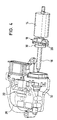
- the drive device shown in Figures 1 to 4 has a general with 10 designated electric motor, one of a pole pot 12 (see FIG. 1) surrounding armature 14 (see FIG. 4), a motor or pole shaft 16 and has a brush system 18, which via motor contacts 20 with a general designated 22 electronic circuit for driving the motor is provided.
- the motor shaft 16 carries in its front area a (not shown) Worm shaft, which meshes with a worm wheel 24.
- the reduction gear thus formed serves to drive one adjustable component, in particular a cover element of an openable Vehicle roofs, for example the cover of a sliding or sliding / lifting roof or a slat of a slat roof.
- the control electronics 22 for the motor 10 is on a circuit board or Board 26 housed, as shown in Figures 1 and 2, itself extends over the worm wheel.
- On the board 26 are preferred further two Hall sensors 28 are arranged to detect by detecting the on of one the magnet shaft 30 arranged magnetic wheel 30 outgoing magnetic field To detect the rotational position of the magnet and thus the pole shaft.
- the board 26 is preferably on both sides with components 44, especially SMD components.
- the pole shaft 16 is in the fully assembled state of the drive device arranged within a shaft housing 32, the one shown in FIG.
- FIG. 3 after top-facing side simultaneously part of the underside of the electronics 22, with 34 designated electronics housing, and preferably is made of plastic.
- 34 designated electronics housing, and preferably is made of plastic.
- the Polshaft 16 enclosed by the shaft housing 32 such that between the Shaft housing 32 and the electronics housing 34 no connection opening consists of, for example, a lubricant of the pole shaft 16 to the board 26 could exit.
- the electronics housing forms 34, in particular the lower part 40 connected to the motor 10, at the same time the lower part of a gear housing 42, in which the Pole shaft 16 meshing worm wheel 24 is housed.
- the electronics housing 34 has a wall surrounding the worm wheel 24 46 on, which thus from the bottom of the electronics housing 34, the Wall 46 and part of the side wall 48 of the electronics housing 34 are formed Lower part of the gear housing by means of a cover 50 opposite the remaining interior of the electronics housing 34 is closed.
- the Lid 50 is made of a material with high thermal conductivity, in particular made of a metallic material and serves as a cooling surface for those on the Board 26 seated and in the fully assembled state of the drive device in circuit elements arranged in close proximity to the cover 50.
- the relevant circuit elements by means of the cooling lugs assigned to the circuit arrangement, thermally conductive Foils, or as shown in FIG. 1 is indicated, by means of a between the circuit arrangement and the housing wall arranged thermally conductive, however electrically insulating foam or fiber body 36 contacted with the lid 50.
- the circuit arrangement can be used by utilizing the cooling effect of the cover 50 place in a plastic housing to control the electric motor, its heat dissipation too low without such additional cooling would also be to ensure trouble-free operation of the drive device if the drive device exceeds the usual size Duration is pressed, for example, is reversed repeatedly (e.g. at Use to drive a lid of an openable vehicle roof Cover is opened and closed repeatedly at short intervals) without that there are sufficiently long cooling pauses between the individual control phases lie.
- the subdivision of the electronics housing proposed here results 34 in several, self-contained housing sections, one extremely compact design of the drive device, in which all for Adjustment of a device to be driven required components housed are in which, however, the individual assemblies spatially apart are arranged separately, and in particular the pole shaft and the transmission comprehensive mechanical part of the drive device of which the electronic Circuit comprising electrical part of the drive device sealed is, so that no lubricant from the mechanical part in the electrical Part can arrive, which leads to a temporary or even permanent impairment function of electrical or electronic components could.
- the cover 52 of the Electronics housing 34 preferably configured so that the board 26 in the Lid can be inserted and locked there.
- the circuit board 26 has openings 54, for example, through which when the board 26 is inserted into the cover 52 on the cover provided locking projections 56 extend through which the board in the Snap the lid into place.
- snap connectors are also preferably provided.
- clip elements 58 are provided be in the corresponding locking projections 60 formed on the lower part 40 snap into place when the cover 52 is placed on the lower part 40.
- bushings 62 provided through which (not shown) Fasteners, e.g. Threaded screws to be pushed through can to fix the drive device stationary.
- metallic reinforcement sleeves 64 are provided in the bushings 62, whose length is matched to the length of the bushings by one Compression stress on the material forming the bushings to prevent when tightening the fastening screws.
- the implementations 62 are all arranged along the outer circumference of the electronics housing 34 and are integrated into the side edge 38 of the same. To the strength of the housing and in particular the attachment points of the housing even further can increase, at least one of the bushings 62 within the outer contour of the electronics housing, as shown at 66 in FIG. 3 indicated is.
- the one proposed here Drive device of an extremely compact and self-contained device With the help of the measures explained here, the Electronics housing, in which preferably the shaft housing and the gear housing are at least partially integrated, are made of plastic, so that not only the one needed to accommodate the drive device Installation space but also the total weight of the drive device without Reduce adverse effects on the operational reliability of the device leaves.
Landscapes
- Engineering & Computer Science (AREA)
- Power Engineering (AREA)
- Connection Of Motors, Electrical Generators, Mechanical Devices, And The Like (AREA)
- Motor Or Generator Frames (AREA)
Applications Claiming Priority (2)
| Application Number | Priority Date | Filing Date | Title |
|---|---|---|---|
| DE10125582A DE10125582A1 (de) | 2001-05-25 | 2001-05-25 | Antriebsvorrichtung |
| DE10125582 | 2001-05-25 |
Publications (4)
| Publication Number | Publication Date |
|---|---|
| EP1261108A2 true EP1261108A2 (fr) | 2002-11-27 |
| EP1261108A8 EP1261108A8 (fr) | 2003-03-05 |
| EP1261108A3 EP1261108A3 (fr) | 2004-08-18 |
| EP1261108B1 EP1261108B1 (fr) | 2008-03-26 |
Family
ID=7686160
Family Applications (1)
| Application Number | Title | Priority Date | Filing Date |
|---|---|---|---|
| EP02010220A Expired - Lifetime EP1261108B1 (fr) | 2001-05-25 | 2002-05-16 | Dispositif d'entraînement |
Country Status (3)
| Country | Link |
|---|---|
| US (1) | US6742413B2 (fr) |
| EP (1) | EP1261108B1 (fr) |
| DE (2) | DE10125582A1 (fr) |
Cited By (2)
| Publication number | Priority date | Publication date | Assignee | Title |
|---|---|---|---|---|
| WO2010034440A1 (fr) * | 2008-09-27 | 2010-04-01 | Valeo Systemes D'essuyage | Commande auxiliaire par moteur électrique pour véhicules |
| WO2014183899A3 (fr) * | 2013-05-17 | 2015-05-14 | Robert Bosch Gmbh | Pièce de contact pour un module d'entraînement, module d'entraînement ainsi que procédé de fabrication d'une pièce de contact |
Families Citing this family (24)
| Publication number | Priority date | Publication date | Assignee | Title |
|---|---|---|---|---|
| FR2840123B1 (fr) * | 2002-05-22 | 2004-08-27 | Meritor Light Vehicle Sys Ltd | Dispositif de motoreduction et connecteur de motoreducteur |
| JP3645877B2 (ja) * | 2002-09-06 | 2005-05-11 | 株式会社シマノ | 自転車用リアディレーラ |
| DE10342756B4 (de) * | 2002-09-17 | 2016-10-06 | Asmo Co., Ltd. | Motor mit einem Steckergehäuse |
| DE102004032017A1 (de) * | 2004-06-28 | 2006-01-12 | Brose Fahrzeugteile Gmbh & Co. Kommanditgesellschaft, Coburg | Antriebseinheit |
| DE602006019962D1 (de) * | 2005-06-10 | 2011-03-17 | Magna Closures Inc | Motorantriebsbaugruppe |
| DE102005038050B4 (de) * | 2005-08-10 | 2009-09-24 | Küster Automotive Door Systems GmbH | Elektromotorisch betriebene Antriebseinheit für Kraftfahrzeuge |
| DE102005040290B4 (de) * | 2005-08-19 | 2010-05-06 | Magna Auteca Ag | Antrieb zur Verstellung von Klappen |
| DE102006017413A1 (de) * | 2006-04-13 | 2007-10-25 | Zf Friedrichshafen Ag | Aktuator für ein zu betätigendes Bauteil eines Kraftfahrzeugs |
| JP5173668B2 (ja) * | 2008-08-18 | 2013-04-03 | 株式会社ミツバ | 減速機構付モータ |
| DE102009043322A1 (de) * | 2009-09-28 | 2011-03-31 | Valeo Systèmes d'Essuyage | Elektromotorischer Hilfsantrieb |
| KR101369266B1 (ko) | 2012-04-25 | 2014-03-07 | 주식회사 케이에스상사 | 개폐모터케이스 조립체 및 조립방법 |
| US9431881B2 (en) * | 2013-03-15 | 2016-08-30 | Regal Beloit America, Inc. | Electric machine housing |
| USD760387S1 (en) * | 2014-03-17 | 2016-06-28 | Intuitive Surgical Operations, Inc. | Surgical instrument end portion |
| USD767129S1 (en) * | 2014-03-17 | 2016-09-20 | Intuitive Surgical Operations, Inc. | Surgical instrument end portion |
| USD767130S1 (en) * | 2014-03-17 | 2016-09-20 | Intuitive Surgical Operations, Inc. | Surgical instrument end portion |
| USD768295S1 (en) * | 2014-03-17 | 2016-10-04 | Intuitive Surgical Operations, Inc. | Surgical instrument end portion |
| BR102014032908A2 (pt) * | 2014-12-29 | 2016-08-16 | Emanuel Manfred Freire Brandt | aparelho para customização de cervejas pós-maturação |
| US10493543B2 (en) * | 2015-03-12 | 2019-12-03 | Robert Bosch Tool Corporation | Power tool motor with reduced electrical noise |
| US11357966B2 (en) | 2015-04-23 | 2022-06-14 | B. Braun Medical Inc. | Compounding device, system, kit, software, and method |
| USD864386S1 (en) | 2016-07-14 | 2019-10-22 | Intuitive Surgical Operations, Inc. | Surgical instrument actuator end portion |
| USD865164S1 (en) | 2016-07-14 | 2019-10-29 | Intuitive Surgical Operations, Inc. | Surgical instrument actuator end portion |
| USD865163S1 (en) | 2016-07-14 | 2019-10-29 | Intuitive Surgical Operations, Inc. | Surgical instrument actuator end portion |
| USD884892S1 (en) | 2018-04-20 | 2020-05-19 | Intuitive Surgical Operations, Inc. | Surgical instrument backend housing |
| DE102019209384A1 (de) * | 2019-06-27 | 2020-12-31 | Geze Gmbh | Gehäuse für einen Antrieb und Antrieb |
Citations (3)
| Publication number | Priority date | Publication date | Assignee | Title |
|---|---|---|---|---|
| US4857812A (en) * | 1986-07-07 | 1989-08-15 | Mitsuba Electric Mfg. Co., Ltd. | Electric motor system for automobiles |
| DE4242641A1 (de) * | 1992-12-17 | 1994-06-23 | Bosch Gmbh Robert | Stellantrieb für Einrichtungen in Kraftfahrzeugen wie zum Beispiel Schiebedach, Fensterheber etc. |
| US6111378A (en) * | 1995-04-28 | 2000-08-29 | Ut Automotive Dearborn, Inc. | Window wiper motor system for an automotive vehicle |
Family Cites Families (13)
| Publication number | Priority date | Publication date | Assignee | Title |
|---|---|---|---|---|
| US4436338A (en) * | 1982-02-17 | 1984-03-13 | Webasto-Werk W. Baier Gmbh & Co. | Operating mechanism for a tiltable sliding cover |
| JPS58214414A (ja) * | 1982-06-07 | 1983-12-13 | Aisin Seiki Co Ltd | 車体におけるサンル−フの安全装置 |
| DE3545869A1 (de) * | 1985-03-27 | 1986-10-09 | Webasto-Werk W. Baier GmbH & Co, 8035 Gauting | Fahrzeugdach |
| US5172605A (en) * | 1990-12-14 | 1992-12-22 | Molon Motor & Coil Corp. | Electric motor gearbox |
| DE4323946C2 (de) | 1993-07-16 | 1999-02-25 | Webasto Karosseriesysteme | Antriebsvorrichtung für ein verstellbares Fahrzeugteil |
| JP3429862B2 (ja) * | 1994-06-30 | 2003-07-28 | カヤバ工業株式会社 | 電動パワーステアリング装置 |
| JPH0861976A (ja) * | 1994-08-18 | 1996-03-08 | Asmo Co Ltd | 移動体の位置及び荷重検出装置 |
| US6003397A (en) * | 1995-10-09 | 1999-12-21 | Asmo Co., Ltd. | Rotary output transmitting structure with a slidable washer |
| JP3864504B2 (ja) | 1997-07-23 | 2007-01-10 | アイシン精機株式会社 | サンルーフ用駆動装置 |
| DE19849837C2 (de) * | 1998-10-29 | 2003-02-20 | Webasto Vehicle Sys Int Gmbh | Tandem-Antriebsvorrichtung für ein verstellbares Fahrzeugdach |
| JP2001069722A (ja) * | 1999-08-31 | 2001-03-16 | Jidosha Denki Kogyo Co Ltd | 開閉装置用回転検出センサ付モータ |
| JP2002036883A (ja) * | 2000-05-15 | 2002-02-06 | Webasto Japan Kk | サンルーフ駆動装置 |
| DE10125581C2 (de) * | 2001-05-25 | 2003-05-08 | Webasto Vehicle Sys Int Gmbh | Antriebsvorrichtung |
-
2001
- 2001-05-25 DE DE10125582A patent/DE10125582A1/de not_active Ceased
-
2002
- 2002-05-16 EP EP02010220A patent/EP1261108B1/fr not_active Expired - Lifetime
- 2002-05-16 DE DE50211943T patent/DE50211943D1/de not_active Expired - Lifetime
- 2002-05-24 US US10/153,871 patent/US6742413B2/en not_active Expired - Lifetime
Patent Citations (3)
| Publication number | Priority date | Publication date | Assignee | Title |
|---|---|---|---|---|
| US4857812A (en) * | 1986-07-07 | 1989-08-15 | Mitsuba Electric Mfg. Co., Ltd. | Electric motor system for automobiles |
| DE4242641A1 (de) * | 1992-12-17 | 1994-06-23 | Bosch Gmbh Robert | Stellantrieb für Einrichtungen in Kraftfahrzeugen wie zum Beispiel Schiebedach, Fensterheber etc. |
| US6111378A (en) * | 1995-04-28 | 2000-08-29 | Ut Automotive Dearborn, Inc. | Window wiper motor system for an automotive vehicle |
Non-Patent Citations (1)
| Title |
|---|
| PATENT ABSTRACTS OF JAPAN Bd. 1996, Nr. 05, 31. Mai 1996 (1996-05-31) & JP 08 011730 A (KAYABA IND CO LTD), 16. Januar 1996 (1996-01-16) * |
Cited By (5)
| Publication number | Priority date | Publication date | Assignee | Title |
|---|---|---|---|---|
| WO2010034440A1 (fr) * | 2008-09-27 | 2010-04-01 | Valeo Systemes D'essuyage | Commande auxiliaire par moteur électrique pour véhicules |
| WO2014183899A3 (fr) * | 2013-05-17 | 2015-05-14 | Robert Bosch Gmbh | Pièce de contact pour un module d'entraînement, module d'entraînement ainsi que procédé de fabrication d'une pièce de contact |
| CN105191076A (zh) * | 2013-05-17 | 2015-12-23 | 罗伯特·博世有限公司 | 用于驱动模块的接触部件,驱动模块以及用于制造接触部件的方法 |
| CN105191076B (zh) * | 2013-05-17 | 2018-08-17 | 罗伯特·博世有限公司 | 用于驱动模块的接触部件,驱动模块以及用于制造接触部件的方法 |
| US10153605B2 (en) | 2013-05-17 | 2018-12-11 | Robert Bosch Gmbh | Contacting part for a drive module, drive module, and method for producing a contacting part |
Also Published As
| Publication number | Publication date |
|---|---|
| US20030015059A1 (en) | 2003-01-23 |
| EP1261108A8 (fr) | 2003-03-05 |
| DE50211943D1 (de) | 2008-05-08 |
| EP1261108B1 (fr) | 2008-03-26 |
| DE10125582A1 (de) | 2002-12-05 |
| US6742413B2 (en) | 2004-06-01 |
| EP1261108A3 (fr) | 2004-08-18 |
Similar Documents
| Publication | Publication Date | Title |
|---|---|---|
| EP1261108A2 (fr) | Dispositif d'entraínement | |
| EP1263119A2 (fr) | Dispositif d'entraínement | |
| DE112016000637B4 (de) | Elektrische Antriebsvorrichtung und elektrische Servolenkvorrichtung | |
| EP0961703B1 (fr) | Ensemble moto-reducteur pour systemes de reglage dans des vehicules automobiles | |
| DE112016000624B4 (de) | Elektrische Antriebseinrichtung und elektrische Servolenkeinrichtung | |
| EP1622241B1 (fr) | Moteur électrique avec degré élevé de protection contre la pénétration des corps étrangers et de l'humidité | |
| DE19839333C1 (de) | Antriebseinrichtung | |
| EP1422809B1 (fr) | Moteur électrique pour entraîner une pompe | |
| EP1351368A1 (fr) | Moteur électrique avec les balais integrés dans le carter de la boíte de vitesse | |
| EP1171680B1 (fr) | Carter de moteur et element polaire cupuliforme, notamment pour moteurs de leve-vitres et de toits ouvrants | |
| WO2009130249A1 (fr) | Dispositif d'entraînement de groupes d'un véhicule | |
| DE19723664A1 (de) | Steuereinheit für einen Elektromotor | |
| DE102013020094A1 (de) | Elektromotor, insbesondere Kühlerlüftermotor | |
| EP2087779A1 (fr) | Appareil de commande compact pour véhicule automobile | |
| DE10306692A1 (de) | Stromversorgungseinheit | |
| EP1188220B1 (fr) | Mecanisme d'entrainement d'une piece de vehicule reglable | |
| DE10331416A1 (de) | Abgedichtetes elektrisches Verbindungssystem | |
| DE102006039280B4 (de) | Motor mit Steuerschaltungsteil | |
| DE69813438T2 (de) | Vorrichtung zur variablen Abdeckung von elektrischen kabelführungen | |
| DE202006016750U1 (de) | Sammelschiene | |
| DE10018020A1 (de) | Gehäuse und Verfahren zu dessen Herstellung | |
| EP2639944A1 (fr) | Moteur électrique | |
| DE102010062034A1 (de) | Schirmungsanordnung für einen bürstenkommutierten Elektromotor sowie Stellgeber mit einem Elektromotor | |
| DE202009008803U1 (de) | Elektrische Maschine | |
| DE10341254A1 (de) | Elektrische Einrichtung eines Kraftfahrzeugs |
Legal Events
| Date | Code | Title | Description |
|---|---|---|---|
| PUAI | Public reference made under article 153(3) epc to a published international application that has entered the european phase |
Free format text: ORIGINAL CODE: 0009012 |
|
| AK | Designated contracting states |
Kind code of ref document: A2 Designated state(s): AT BE CH CY DE DK ES FI FR GB GR IE IT LI LU MC NL PT SE TR |
|
| AX | Request for extension of the european patent |
Free format text: AL;LT;LV;MK;RO;SI |
|
| RAP1 | Party data changed (applicant data changed or rights of an application transferred) |
Owner name: WEBASTO VEHICLE SYSTEMS INTERNATIONAL GMBH |
|
| PUAL | Search report despatched |
Free format text: ORIGINAL CODE: 0009013 |
|
| AK | Designated contracting states |
Kind code of ref document: A3 Designated state(s): AT BE CH CY DE DK ES FI FR GB GR IE IT LI LU MC NL PT SE TR |
|
| AX | Request for extension of the european patent |
Extension state: AL LT LV MK RO SI |
|
| 17P | Request for examination filed |
Effective date: 20041127 |
|
| AKX | Designation fees paid |
Designated state(s): DE FR GB |
|
| RBV | Designated contracting states (corrected) |
Designated state(s): DE FR GB |
|
| GRAP | Despatch of communication of intention to grant a patent |
Free format text: ORIGINAL CODE: EPIDOSNIGR1 |
|
| RAP1 | Party data changed (applicant data changed or rights of an application transferred) |
Owner name: WEBASTO AG |
|
| GRAS | Grant fee paid |
Free format text: ORIGINAL CODE: EPIDOSNIGR3 |
|
| GRAA | (expected) grant |
Free format text: ORIGINAL CODE: 0009210 |
|
| AK | Designated contracting states |
Kind code of ref document: B1 Designated state(s): DE FR GB |
|
| REG | Reference to a national code |
Ref country code: GB Ref legal event code: FG4D Free format text: NOT ENGLISH |
|
| REF | Corresponds to: |
Ref document number: 50211943 Country of ref document: DE Date of ref document: 20080508 Kind code of ref document: P |
|
| ET | Fr: translation filed | ||
| PLBE | No opposition filed within time limit |
Free format text: ORIGINAL CODE: 0009261 |
|
| STAA | Information on the status of an ep patent application or granted ep patent |
Free format text: STATUS: NO OPPOSITION FILED WITHIN TIME LIMIT |
|
| 26N | No opposition filed |
Effective date: 20081230 |
|
| REG | Reference to a national code |
Ref country code: FR Ref legal event code: PLFP Year of fee payment: 15 |
|
| REG | Reference to a national code |
Ref country code: FR Ref legal event code: PLFP Year of fee payment: 16 |
|
| REG | Reference to a national code |
Ref country code: FR Ref legal event code: PLFP Year of fee payment: 17 |
|
| PGFP | Annual fee paid to national office [announced via postgrant information from national office to epo] |
Ref country code: DE Payment date: 20190522 Year of fee payment: 18 |
|
| PGFP | Annual fee paid to national office [announced via postgrant information from national office to epo] |
Ref country code: FR Payment date: 20190521 Year of fee payment: 18 |
|
| PGFP | Annual fee paid to national office [announced via postgrant information from national office to epo] |
Ref country code: GB Payment date: 20190523 Year of fee payment: 18 |
|
| REG | Reference to a national code |
Ref country code: DE Ref legal event code: R119 Ref document number: 50211943 Country of ref document: DE |
|
| GBPC | Gb: european patent ceased through non-payment of renewal fee |
Effective date: 20200516 |
|
| PG25 | Lapsed in a contracting state [announced via postgrant information from national office to epo] |
Ref country code: FR Free format text: LAPSE BECAUSE OF NON-PAYMENT OF DUE FEES Effective date: 20200531 Ref country code: GB Free format text: LAPSE BECAUSE OF NON-PAYMENT OF DUE FEES Effective date: 20200516 |
|
| PG25 | Lapsed in a contracting state [announced via postgrant information from national office to epo] |
Ref country code: DE Free format text: LAPSE BECAUSE OF NON-PAYMENT OF DUE FEES Effective date: 20201201 |