EP1258695A1 - Culot pour munition destiné à recevoir un allumeur électrique - Google Patents
Culot pour munition destiné à recevoir un allumeur électrique Download PDFInfo
- Publication number
- EP1258695A1 EP1258695A1 EP02291111A EP02291111A EP1258695A1 EP 1258695 A1 EP1258695 A1 EP 1258695A1 EP 02291111 A EP02291111 A EP 02291111A EP 02291111 A EP02291111 A EP 02291111A EP 1258695 A1 EP1258695 A1 EP 1258695A1
- Authority
- EP
- European Patent Office
- Prior art keywords
- base
- igniter
- ring
- base according
- conductive
- Prior art date
- Legal status (The legal status is an assumption and is not a legal conclusion. Google has not performed a legal analysis and makes no representation as to the accuracy of the status listed.)
- Granted
Links
- 239000000463 material Substances 0.000 claims abstract description 12
- 239000004033 plastic Substances 0.000 claims abstract description 7
- 239000007769 metal material Substances 0.000 claims abstract description 4
- 239000011368 organic material Substances 0.000 claims abstract 2
- 239000011810 insulating material Substances 0.000 claims description 10
- RYGMFSIKBFXOCR-UHFFFAOYSA-N Copper Chemical compound [Cu] RYGMFSIKBFXOCR-UHFFFAOYSA-N 0.000 claims description 6
- 229910052802 copper Inorganic materials 0.000 claims description 6
- 239000010949 copper Substances 0.000 claims description 6
- 229910001369 Brass Inorganic materials 0.000 claims description 3
- 229910000881 Cu alloy Inorganic materials 0.000 claims description 3
- 239000010951 brass Substances 0.000 claims description 3
- 238000010079 rubber tapping Methods 0.000 claims description 3
- 238000001465 metallisation Methods 0.000 claims description 2
- 239000004020 conductor Substances 0.000 abstract description 4
- -1 polyoxymethylene Polymers 0.000 description 5
- 229920001343 polytetrafluoroethylene Polymers 0.000 description 5
- 239000004810 polytetrafluoroethylene Substances 0.000 description 5
- 239000008188 pellet Substances 0.000 description 3
- 229930040373 Paraformaldehyde Natural products 0.000 description 2
- 238000010292 electrical insulation Methods 0.000 description 2
- 239000007789 gas Substances 0.000 description 2
- 238000009413 insulation Methods 0.000 description 2
- 239000002184 metal Substances 0.000 description 2
- 229910052751 metal Inorganic materials 0.000 description 2
- 229920006324 polyoxymethylene Polymers 0.000 description 2
- 239000003380 propellant Substances 0.000 description 2
- 238000007789 sealing Methods 0.000 description 2
- 239000000020 Nitrocellulose Substances 0.000 description 1
- 239000000853 adhesive Substances 0.000 description 1
- 230000000295 complement effect Effects 0.000 description 1
- 230000005684 electric field Effects 0.000 description 1
- 238000010304 firing Methods 0.000 description 1
- PCHJSUWPFVWCPO-UHFFFAOYSA-N gold Chemical compound [Au] PCHJSUWPFVWCPO-UHFFFAOYSA-N 0.000 description 1
- 239000010931 gold Substances 0.000 description 1
- 229910052737 gold Inorganic materials 0.000 description 1
- 239000012535 impurity Substances 0.000 description 1
- 230000000977 initiatory effect Effects 0.000 description 1
- 238000009434 installation Methods 0.000 description 1
- 238000011900 installation process Methods 0.000 description 1
- 239000012212 insulator Substances 0.000 description 1
- 229920001220 nitrocellulos Polymers 0.000 description 1
- 230000002093 peripheral effect Effects 0.000 description 1
- 230000001681 protective effect Effects 0.000 description 1
- 239000004065 semiconductor Substances 0.000 description 1
- 230000007704 transition Effects 0.000 description 1
Images


Classifications
-
- F—MECHANICAL ENGINEERING; LIGHTING; HEATING; WEAPONS; BLASTING
- F42—AMMUNITION; BLASTING
- F42B—EXPLOSIVE CHARGES, e.g. FOR BLASTING, FIREWORKS, AMMUNITION
- F42B5/00—Cartridge ammunition, e.g. separately-loaded propellant charges
- F42B5/02—Cartridges, i.e. cases with charge and missile
- F42B5/18—Caseless ammunition; Cartridges having combustible cases
- F42B5/181—Caseless ammunition; Cartridges having combustible cases consisting of a combustible casing wall and a metal base; Connectors therefor
-
- F—MECHANICAL ENGINEERING; LIGHTING; HEATING; WEAPONS; BLASTING
- F42—AMMUNITION; BLASTING
- F42B—EXPLOSIVE CHARGES, e.g. FOR BLASTING, FIREWORKS, AMMUNITION
- F42B5/00—Cartridge ammunition, e.g. separately-loaded propellant charges
- F42B5/02—Cartridges, i.e. cases with charge and missile
- F42B5/08—Cartridges, i.e. cases with charge and missile modified for electric ignition
-
- F—MECHANICAL ENGINEERING; LIGHTING; HEATING; WEAPONS; BLASTING
- F42—AMMUNITION; BLASTING
- F42C—AMMUNITION FUZES; ARMING OR SAFETY MEANS THEREFOR
- F42C19/00—Details of fuzes
- F42C19/08—Primers; Detonators
- F42C19/12—Primers; Detonators electric
Definitions
- the technical field of the invention is that of ammunition caps which are intended to receive a electric igniter.
- Such bases are generally secured to a case ammunition and they are intended to ensure when firing sealing against propellant gases.
- igniters usually have a axial touch to ensure a current supply
- the current return is generally carried out by through the projectile in contact with ground weapon.
- the mass of the weapon is used as return conductor there are insulation problems electric.
- the weapon is energized during the initiation of ammunition which can degrade equipment, in particular electronic, attached to the weapon and also risks injuring the gunmen.
- igniters high voltage electrical in the form of one or several plasma torches or ignitors.
- the tensions are then in the order of a few tens of kilo volts.
- the base according to the invention ensures a reliable electrical connection between an electrical igniter and a weapon system while ensuring an excellent level electrical insulation.
- Contact resistances present at a base according to the invention are weak and reproducible from one base to another.
- the invention relates to a base for ammunition intended to receive an electric igniter arranged in a axial bore, base characterized in that it is produced in a metallic material covered by an insulating material and in that it comprises at least one non-conductive zone isolated, constituted by an annular support zone of a shoulder of the base or by at least one conductive ring not insulated and set in a housing fitted on the base.
- the axial bore includes a thread intended to ensure the fixing of the igniter, the thread being free from insulating material and ensuring an electrical connection between the non-insulated conductive area and the igniter through the base material.
- the insulating material may be a plastic material or organic.
- the ring housing can be a groove circular made at a rear face of the base.
- the housing may have a trapezoidal profile in section.
- the conductive ring can be made of copper or Brass.
- the conductive area especially the support area annular of a shoulder of the base, may be covered a metallization of copper or copper alloy.
- the base according to the invention can advantageously carry an electric igniter comprising at least one plasma igniter.
- a base 1 according to a first embodiment of the invention comprises a background 2 massive and a cylindrical rim 3 at the end of which a rubber sealing lip 4 is arranged.
- This base is intended to be fixed to an ammunition case not shown, case conventionally containing a propellant charge and carrying a projectile.
- the base 1 has a threaded axial bore 5 which receives an igniter 6.
- the igniter 6 shown here is a plasma igniter. This includes an extended metal tubular body 7 by a diffuser 8 for the plasma generated. This diffuser is drilled with radial holes 9.
- the body 7 carries a thread 7a allowing its fixing in the thread 5 of the base.
- the rear part 7b of the body 7 has an enlarged diameter and constitutes a collar axial stop being housed in a countersink 10 of the base.
- the body 7 has an axial bore 11 inside which is arranged a cylindrical insulating case 12 made in a plastic material likely to ablate, it is say to generate light gases by the action of a plasma.
- a cylindrical insulating case 12 made in a plastic material likely to ablate, it is say to generate light gases by the action of a plasma.
- Such a case is generally called a capillary in known plasma torches.
- Two metal electrodes 13 and 14 are separated by the case insulator 12.
- the front end 13b of the rear electrode forms a point allowing to constitute a foot for the arch electric which will generate the plasma.
- An annular front electrode 14 is applied against an internal counterbore 7c of the body 7. It has a peripheral shoulder which is adjusted tightly with the body 7.
- the front 14 and rear 13 electrodes are separate axially by a distance which is chosen such that (for the chosen electric voltage) the electric field between the electrodes is of the order of 1 mega volt / meter. AT as an example for a voltage between electrodes of 10,000 Volts, the distance will be 10 mm.
- the rear electrode 13 is held axially by relative to the body 7 by an insulating sleeve 15 which carries a thread 16 allowing its screwing at the level of a tapping rear of the body 7.
- the socket is supported on a shoulder of the rear electrode 13 and apply this against the case 12, itself in abutment against the electrode before 14.
- the sleeve 15 is made of an insulating material with high mechanical strength, for example polyoxymethylene.
- the plasma igniter could also be replaced by another type of electric igniter, for example with wire hot, exploded wire, semiconductor bridge or projected layer (better known as “slapper”).
- igniters will, however, all have for common points to include, on the one hand an axial touch 13a allowing the arrival of the current and on the other hand a conductive body 7 allowing current return and having a thread.
- the base 1 is made of a metallic material and it comprises at least one conductive ring 17.
- This ring 17 is set in a housing 18 arranged on the base.
- the ring will be made of a malleable material and reduced electrical resistance, for example copper or Brass. The installation of the ring in its housing will be carried out by cold deformation of the ring in its housing by means of a press.
- the ring is intended, like the touch 13a, for cooperate with a mobile contact integral with a system weapon (not shown).
- the circular shape of the ring avoids any constraint of angular indexing of the base compared to the weapon.
- the housing 18 for the ring 17 is a groove circular machined at a rear face 2a of the bottom 2 pellet 1.
- This housing 18 has in section a profile trapezoidal inside which the material of the ring 17 penetrates when it is put in place. Such a arrangement ensures the attachment of the ring with the base while reducing the electrical resistance of the contact between the ring and the base.
- the base 1 is covered by an insulating material (shown schematically by the dotted lines 19) which covers substantially its entire surface except for the ring 17 and axial thread 5.
- This insulating material will for example be a vacuum deposit from 30 to 80 micrometers of a plastic material such as polytetrafluoroethylene (PTFE) or another material insulating organic, such as di-para-zylylene (DPXN).
- PTFE polytetrafluoroethylene
- DPXN di-para-zylylene
- the insulating deposit will be produced after fitting of the ring 17 and the igniter 6. Thus it will also cover the outer surface of the body 7 of the igniter and the transition zones between the base and igniter.
- a protective sheet for example a self-adhesive plastic
- This protection will be removed manually after completion of the insulating deposit or else before using the base.
- first contact mobile abuts against the axial touch 13a and a second movable contact bears against the ring 17.
- These mobile contacts will for example be carried by the breech closing the chamber of the weapon.
- the radial distance between the ring 17 and the touch axial 13a is of the order of 50 mm for a caliber of 120mm. There is therefore no risk of seeing an arc appear electric directly between ring and touch for a voltage between 10 and 30 kilo volts.
- the electrical contact resistances are strongly reduced between ring 17 and base 1 due to the mutual contact surface between these elements which is important, the installation process ensuring by elsewhere an intimate contact between ring 17 and base 1.
- the electrical contact resistances are also greatly reduced between the base 1 and the body 7 of igniter. In fact the current flows through the thread 7a and complementary thread 5, the surfaces again are relatively important and the tightening ensures the quality of the electrical contact.
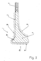
- Figure 3 shows schematically another embodiment of a base according to the invention.
- This base differs from the previous one in that its rear face has no conductive ring 17.
- the current return then takes place via a conductive area constituted by an annular bearing face 2b of a shoulder of the base, area which is intended to come into abutment against a conductive surface of the weapon chamber or well preferably against a touch carried by the weapon.
- the bearing surface 2b of the shoulder is covered with a copper deposit.
- the rest of the external surface of the base 1 is covered with an insulating material 19.
- a material plastic such as polytetrafluoroethylene (PTFE) or di-para-zylylene (DPXN).
- the current will reach the igniter via ground conductor of the base and the conductor body of the igniter, the electrical contact between these two elements being obtained by the threaded connection base / igniter.
- the current return will be carried out by the axial touch of the igniter.
- This embodiment of the invention is more particularly suitable for medium or small munitions caliber (caliber less than 50mm).
Landscapes
- Engineering & Computer Science (AREA)
- General Engineering & Computer Science (AREA)
- Spark Plugs (AREA)
- Lock And Its Accessories (AREA)
- Catching Or Destruction (AREA)
- Fuses (AREA)
- Ignition Installations For Internal Combustion Engines (AREA)
Abstract
Description
- la figure 1 montre en coupe longitudinale un culot selon un premier mode de réalisation de l'invention équipé d'un allumeur électrique,
- la figure 2 montre ce culot en perspective arrière et en partie arrachée,
- la figure 3 montre en coupe longitudinale un culot selon un deuxième mode de réalisation de l'invention.
Claims (8)
- Culot (1) pour munition destiné à recevoir un allumeur électrique (6) disposé dans un alésage axial (5), culot caractérisé en ce qu' il est réalisé en un matériau métallique recouvert par un matériau isolant (19) et en ce qu'il comporte au moins une zone conductrice non isolée (17,2b), constituée par une zone d'appui annulaire (2b) d'un épaulement du culot ou par au moins une bague conductrice (17) non isolée et sertie dans un logement (18) aménagé sur le culot (1).
- Culot selon la revendication 1, caractérisé en ce que l'alésage axial (5) comporte un taraudage destiné à assurer la fixation de l'allumeur (6), le taraudage étant libre de matériau isolant et assurant une connexion électrique entre la zone conductrice non isolée (17,2b) et l'allumeur (6) au travers du matériau du culot (1).
- Culot selon une des revendications 1 ou 2,
caractérisé en ce que le matériau isolant (19) est une matière plastique ou organique. - Culot selon une des revendications 1 à 3,
caractérisé en ce que le logement (18) de la bague (17) est un sillon circulaire réalisé au niveau d'une face arrière du culot. - Culot selon la revendication 4, caractérisé en ce que le logement (18) a un profil trapézoïdal en section.
- Culot selon une des revendications 1 à 5,
caractérisé en ce que la bague conductrice (17) est réalisée en cuivre ou en laiton. - Culot selon une des revendications 1 à 3,
caractérisé en ce que la zone conductrice (2b) est recouverte d'une métallisation de cuivre ou d'alliage de cuivre. - Culot selon une des revendications 1 à 7,
caractérisé en ce qu'il porte un allumeur électrique (6) comprenant au moins un allumeur à plasma.
Applications Claiming Priority (2)
| Application Number | Priority Date | Filing Date | Title |
|---|---|---|---|
| FR0106688 | 2001-05-18 | ||
| FR0106688A FR2824898B1 (fr) | 2001-05-18 | 2001-05-18 | Culot pour munition destine a recevoir un allumeur electrique |
Publications (2)
| Publication Number | Publication Date |
|---|---|
| EP1258695A1 true EP1258695A1 (fr) | 2002-11-20 |
| EP1258695B1 EP1258695B1 (fr) | 2006-08-09 |
Family
ID=8863512
Family Applications (1)
| Application Number | Title | Priority Date | Filing Date |
|---|---|---|---|
| EP02291111A Expired - Lifetime EP1258695B1 (fr) | 2001-05-18 | 2002-05-03 | Culot pour munition destiné à recevoir un allumeur électrique |
Country Status (5)
| Country | Link |
|---|---|
| US (1) | US6644204B2 (fr) |
| EP (1) | EP1258695B1 (fr) |
| AT (1) | ATE335985T1 (fr) |
| DE (1) | DE60213709T2 (fr) |
| FR (1) | FR2824898B1 (fr) |
Cited By (3)
| Publication number | Priority date | Publication date | Assignee | Title |
|---|---|---|---|---|
| US6796243B2 (en) * | 2002-03-26 | 2004-09-28 | Rheinmetall W & M Gmbh | Cartridge |
| FR2915564A1 (fr) * | 2007-04-30 | 2008-10-31 | Nexter Munitions Sa | Dispositif electromecanique d'adaptation d'un obus |
| FR3092660A1 (fr) | 2019-02-13 | 2020-08-14 | Nexter Munitions | Fusee pour un projectile destine a etre tire par un canon |
Families Citing this family (34)
| Publication number | Priority date | Publication date | Assignee | Title |
|---|---|---|---|---|
| SE524623C2 (sv) | 2002-08-08 | 2004-09-07 | Bofors Defence Ab | Isolerad patronhylsa och ammunition, förfarande för tillverkning av dylika hylsor och ammunition samt användning av dylika hylsor och ammunition vid flera skilda vapensystem |
| DE102006017100B4 (de) * | 2006-04-07 | 2012-10-31 | Bae Systems Bofors Ab | Zünder |
| US7878120B1 (en) * | 2007-12-20 | 2011-02-01 | The United States Of America As Represented By The Secretary Of The Army | Ammunition data link |
| US8607702B1 (en) * | 2010-01-15 | 2013-12-17 | The United States Of America As Represented By The Secretary Of The Army | Low energy ignition system for large and medium caliber ammunition |
| US10876822B2 (en) | 2017-11-09 | 2020-12-29 | True Velocity Ip Holdings, Llc | Multi-piece polymer ammunition cartridge |
| US8561543B2 (en) | 2010-11-10 | 2013-10-22 | True Velocity, Inc. | Lightweight polymer ammunition cartridge casings |
| US11047664B2 (en) | 2010-11-10 | 2021-06-29 | True Velocity Ip Holdings, Llc | Lightweight polymer ammunition cartridge casings |
| US11231257B2 (en) | 2010-11-10 | 2022-01-25 | True Velocity Ip Holdings, Llc | Method of making a metal injection molded ammunition cartridge |
| US10480915B2 (en) | 2010-11-10 | 2019-11-19 | True Velocity Ip Holdings, Llc | Method of making a polymeric subsonic ammunition cartridge |
| US9885551B2 (en) | 2010-11-10 | 2018-02-06 | True Velocity, Inc. | Subsonic polymeric ammunition |
| US11300393B2 (en) | 2010-11-10 | 2022-04-12 | True Velocity Ip Holdings, Llc | Polymer ammunition having a MIM primer insert |
| US11340050B2 (en) | 2010-11-10 | 2022-05-24 | True Velocity Ip Holdings, Llc | Subsonic polymeric ammunition cartridge |
| US10408592B2 (en) | 2010-11-10 | 2019-09-10 | True Velocity Ip Holdings, Llc | One piece polymer ammunition cartridge having a primer insert and methods of making the same |
| US10352670B2 (en) | 2010-11-10 | 2019-07-16 | True Velocity Ip Holdings, Llc | Lightweight polymer ammunition cartridge casings |
| US11313654B2 (en) | 2010-11-10 | 2022-04-26 | True Velocity Ip Holdings, Llc | Polymer ammunition having a projectile made by metal injection molding |
| US9835427B2 (en) * | 2016-03-09 | 2017-12-05 | True Velocity, Inc. | Two-piece primer insert for polymer ammunition |
| US10760882B1 (en) | 2017-08-08 | 2020-09-01 | True Velocity Ip Holdings, Llc | Metal injection molded ammunition cartridge |
| US11733015B2 (en) | 2018-07-06 | 2023-08-22 | True Velocity Ip Holdings, Llc | Multi-piece primer insert for polymer ammunition |
| AU2019299431B2 (en) | 2018-07-06 | 2023-06-15 | True Velocity Ip Holdings, Llc | Three-piece primer insert for polymer ammunition |
| US10704879B1 (en) | 2019-02-14 | 2020-07-07 | True Velocity Ip Holdings, Llc | Polymer ammunition and cartridge having a convex primer insert |
| US10731957B1 (en) | 2019-02-14 | 2020-08-04 | True Velocity Ip Holdings, Llc | Polymer ammunition and cartridge having a convex primer insert |
| USD893667S1 (en) | 2019-03-11 | 2020-08-18 | True Velocity Ip Holdings, Llc | Ammunition cartridge nose having an angled shoulder |
| USD893668S1 (en) | 2019-03-11 | 2020-08-18 | True Velocity Ip Holdings, Llc | Ammunition cartridge nose having an angled shoulder |
| USD893666S1 (en) | 2019-03-11 | 2020-08-18 | True Velocity Ip Holdings, Llc | Ammunition cartridge nose having an angled shoulder |
| USD893665S1 (en) | 2019-03-11 | 2020-08-18 | True Velocity Ip Holdings, Llc | Ammunition cartridge nose having an angled shoulder |
| USD891567S1 (en) | 2019-03-12 | 2020-07-28 | True Velocity Ip Holdings, Llc | Ammunition cartridge nose having an angled shoulder |
| USD891570S1 (en) | 2019-03-12 | 2020-07-28 | True Velocity Ip Holdings, Llc | Ammunition cartridge nose |
| USD892258S1 (en) | 2019-03-12 | 2020-08-04 | True Velocity Ip Holdings, Llc | Ammunition cartridge nose having an angled shoulder |
| USD891569S1 (en) | 2019-03-12 | 2020-07-28 | True Velocity Ip Holdings, Llc | Ammunition cartridge nose having an angled shoulder |
| USD891568S1 (en) | 2019-03-12 | 2020-07-28 | True Velocity Ip Holdings, Llc | Ammunition cartridge nose having an angled shoulder |
| WO2020197868A2 (fr) | 2019-03-19 | 2020-10-01 | True Velocity Ip Holdings, Llc | Procédés et dispositifs de dosage et de compactage de poudres explosives |
| USD894320S1 (en) | 2019-03-21 | 2020-08-25 | True Velocity Ip Holdings, Llc | Ammunition Cartridge |
| EP3999799A4 (fr) | 2019-07-16 | 2023-07-26 | True Velocity IP Holdings, LLC | Munition polymère ayant un auxiliaire d'alignement, cartouche et procédé de fabrication associé |
| US11988491B1 (en) * | 2021-07-29 | 2024-05-21 | Revolutionary Rounds L.L.C. | Projectile and caseless cartridge |
Citations (7)
| Publication number | Priority date | Publication date | Assignee | Title |
|---|---|---|---|---|
| GB2056631A (en) * | 1979-08-14 | 1981-03-18 | Buck Chem Tech Werke | Contact head for projectiles capable of being fired from electrically actuable launcher |
| EP0310517A1 (fr) * | 1987-10-01 | 1989-04-05 | GIAT Industries | Culot pour munition de gros calibre comportant un allumeur électrique |
| US5355764A (en) | 1992-05-04 | 1994-10-18 | Fmc Corporation | Plasma actuated ignition and distribution pump |
| WO1995030874A1 (fr) * | 1994-05-05 | 1995-11-16 | General Dynamics Land Systems, Inc. | Generateurs de plasma pour cartouches de canons electrothermiques |
| US5503081A (en) | 1993-11-22 | 1996-04-02 | Fmc Corp | Annular plasma injector |
| EP0905470A1 (fr) | 1997-09-24 | 1999-03-31 | Giat Industries | Composant d'allumage pour composition pyrotechnique ou charge propulsive |
| DE19853291A1 (de) * | 1998-11-19 | 2000-05-31 | Tzn Forschung & Entwicklung | Aus einer großkalibrigen Waffe verschießbare Patrone |
Family Cites Families (1)
| Publication number | Priority date | Publication date | Assignee | Title |
|---|---|---|---|---|
| US5044278A (en) * | 1989-07-03 | 1991-09-03 | James E. Meagher | Electrically ignitible cartridge system |
-
2001
- 2001-05-18 FR FR0106688A patent/FR2824898B1/fr not_active Expired - Fee Related
-
2002
- 2002-05-03 AT AT02291111T patent/ATE335985T1/de not_active IP Right Cessation
- 2002-05-03 EP EP02291111A patent/EP1258695B1/fr not_active Expired - Lifetime
- 2002-05-03 DE DE60213709T patent/DE60213709T2/de not_active Expired - Fee Related
- 2002-05-15 US US10/145,136 patent/US6644204B2/en not_active Expired - Fee Related
Patent Citations (7)
| Publication number | Priority date | Publication date | Assignee | Title |
|---|---|---|---|---|
| GB2056631A (en) * | 1979-08-14 | 1981-03-18 | Buck Chem Tech Werke | Contact head for projectiles capable of being fired from electrically actuable launcher |
| EP0310517A1 (fr) * | 1987-10-01 | 1989-04-05 | GIAT Industries | Culot pour munition de gros calibre comportant un allumeur électrique |
| US5355764A (en) | 1992-05-04 | 1994-10-18 | Fmc Corporation | Plasma actuated ignition and distribution pump |
| US5503081A (en) | 1993-11-22 | 1996-04-02 | Fmc Corp | Annular plasma injector |
| WO1995030874A1 (fr) * | 1994-05-05 | 1995-11-16 | General Dynamics Land Systems, Inc. | Generateurs de plasma pour cartouches de canons electrothermiques |
| EP0905470A1 (fr) | 1997-09-24 | 1999-03-31 | Giat Industries | Composant d'allumage pour composition pyrotechnique ou charge propulsive |
| DE19853291A1 (de) * | 1998-11-19 | 2000-05-31 | Tzn Forschung & Entwicklung | Aus einer großkalibrigen Waffe verschießbare Patrone |
Cited By (5)
| Publication number | Priority date | Publication date | Assignee | Title |
|---|---|---|---|---|
| US6796243B2 (en) * | 2002-03-26 | 2004-09-28 | Rheinmetall W & M Gmbh | Cartridge |
| FR2915564A1 (fr) * | 2007-04-30 | 2008-10-31 | Nexter Munitions Sa | Dispositif electromecanique d'adaptation d'un obus |
| FR3092660A1 (fr) | 2019-02-13 | 2020-08-14 | Nexter Munitions | Fusee pour un projectile destine a etre tire par un canon |
| WO2020165699A1 (fr) | 2019-02-13 | 2020-08-20 | Nexter Munitions | Fusee pour un projectile destine a etre tire par un canon |
| US11774225B2 (en) | 2019-02-13 | 2023-10-03 | Nexter Munitions | Fuze for a projectile intended to be fired by a cannon |
Also Published As
| Publication number | Publication date |
|---|---|
| US20020170455A1 (en) | 2002-11-21 |
| DE60213709D1 (de) | 2006-09-21 |
| DE60213709T2 (de) | 2007-08-16 |
| US6644204B2 (en) | 2003-11-11 |
| ATE335985T1 (de) | 2006-09-15 |
| FR2824898B1 (fr) | 2003-09-12 |
| FR2824898A1 (fr) | 2002-11-22 |
| EP1258695B1 (fr) | 2006-08-09 |
Similar Documents
| Publication | Publication Date | Title |
|---|---|---|
| EP1258695B1 (fr) | Culot pour munition destiné à recevoir un allumeur électrique | |
| EP0905470B1 (fr) | Composant d'allumage pour composition pyrotechnique ou charge propulsive | |
| EP1092940A1 (fr) | Dispositif d'allumage pour un chargement propulsif | |
| FR2807610A1 (fr) | Torche a plasma incorporant un fusible d'amorcage reactif et tube allumeur integrant une telle torche | |
| FR2807611A1 (fr) | Torche plasma comportant des electrodes separees par un entrefer et allumeur incorporant une telle torche | |
| FR2865264A1 (fr) | Bougie de prechauffage et procede de fabrication d'une telle bougie | |
| EP0837621B1 (fr) | Torche à plasma avec nouvelles caractéristiques d'étanchéité | |
| EP3715776A1 (fr) | Cartouche comprenant des cordeaux d`allumage | |
| US20030029857A1 (en) | Heater | |
| EP0717256B1 (fr) | Système de mise à feu par arc électrique d'une munition sans douille | |
| EP1273875B1 (fr) | Dispositif d'allumage pour un chargement propulsif | |
| FR2987891A1 (fr) | Projectile sous calibre a structure de tete amenagee | |
| EP0526315A1 (fr) | Contacteur électrique à commande pyrotechnique | |
| FR2702554A1 (fr) | Munition, en particulier pour arme de gros calibre. | |
| FR2539658A1 (fr) | Tube de guidage d'un fil de metal d'apport pour une installation de soudage par arc electrique | |
| FR2844873A1 (fr) | Inflammateur a double effet et procede d'allumage mettant en oeuvre un tel inflammateur | |
| EP2559119B1 (fr) | Bougie d'allumage équipée de moyens de prévention des courts-circuits | |
| FR2545206A1 (fr) | Dispositif d'amorcage electrique a percussion pour cones de combat | |
| FR2621388A1 (fr) | Culot pour munition de gros calibre comportant un allumeur electrique | |
| EP1565963B1 (fr) | Connecteur pour traversee electrique a fort amperage | |
| WO2015173017A1 (fr) | Electrode de prechauffage a joint d'isolation | |
| EP0147314A2 (fr) | Culot obturateur en matériau non métallique | |
| FR2683396A1 (fr) | Contact electrique pour cable electrique a ame en aluminium et connecteur electrique equipe d'au moins un tel contact. | |
| EP2219007B1 (fr) | Procédé de fixation d'un projectile en matière plastique sur un étui métallique et projectile permettant la mise en oeuvre de ce procédé | |
| FR3147444A1 (fr) | Connecteur electrique |
Legal Events
| Date | Code | Title | Description |
|---|---|---|---|
| PUAI | Public reference made under article 153(3) epc to a published international application that has entered the european phase |
Free format text: ORIGINAL CODE: 0009012 |
|
| AK | Designated contracting states |
Kind code of ref document: A1 Designated state(s): AT BE CH CY DE DK ES FI FR GB GR IE IT LI LU MC NL PT SE TR |
|
| AX | Request for extension of the european patent |
Free format text: AL;LT;LV;MK;RO;SI |
|
| 17P | Request for examination filed |
Effective date: 20021227 |
|
| AKX | Designation fees paid |
Designated state(s): AT BE CH CY DE DK ES FI FR GB GR IE IT LI LU MC NL PT SE TR |
|
| GRAP | Despatch of communication of intention to grant a patent |
Free format text: ORIGINAL CODE: EPIDOSNIGR1 |
|
| GRAS | Grant fee paid |
Free format text: ORIGINAL CODE: EPIDOSNIGR3 |
|
| GRAA | (expected) grant |
Free format text: ORIGINAL CODE: 0009210 |
|
| AK | Designated contracting states |
Kind code of ref document: B1 Designated state(s): AT BE CH CY DE DK ES FI FR GB GR IE IT LI LU MC NL PT SE TR |
|
| PG25 | Lapsed in a contracting state [announced via postgrant information from national office to epo] |
Ref country code: IT Free format text: LAPSE BECAUSE OF FAILURE TO SUBMIT A TRANSLATION OF THE DESCRIPTION OR TO PAY THE FEE WITHIN THE PRESCRIBED TIME-LIMIT;WARNING: LAPSES OF ITALIAN PATENTS WITH EFFECTIVE DATE BEFORE 2007 MAY HAVE OCCURRED AT ANY TIME BEFORE 2007. THE CORRECT EFFECTIVE DATE MAY BE DIFFERENT FROM THE ONE RECORDED. Effective date: 20060809 Ref country code: IE Free format text: LAPSE BECAUSE OF FAILURE TO SUBMIT A TRANSLATION OF THE DESCRIPTION OR TO PAY THE FEE WITHIN THE PRESCRIBED TIME-LIMIT Effective date: 20060809 Ref country code: AT Free format text: LAPSE BECAUSE OF FAILURE TO SUBMIT A TRANSLATION OF THE DESCRIPTION OR TO PAY THE FEE WITHIN THE PRESCRIBED TIME-LIMIT Effective date: 20060809 Ref country code: FI Free format text: LAPSE BECAUSE OF FAILURE TO SUBMIT A TRANSLATION OF THE DESCRIPTION OR TO PAY THE FEE WITHIN THE PRESCRIBED TIME-LIMIT Effective date: 20060809 Ref country code: NL Free format text: LAPSE BECAUSE OF FAILURE TO SUBMIT A TRANSLATION OF THE DESCRIPTION OR TO PAY THE FEE WITHIN THE PRESCRIBED TIME-LIMIT Effective date: 20060809 |
|
| REG | Reference to a national code |
Ref country code: GB Ref legal event code: FG4D Free format text: NOT ENGLISH |
|
| REG | Reference to a national code |
Ref country code: CH Ref legal event code: EP |
|
| GBT | Gb: translation of ep patent filed (gb section 77(6)(a)/1977) |
Effective date: 20060816 |
|
| REG | Reference to a national code |
Ref country code: IE Ref legal event code: FG4D Free format text: LANGUAGE OF EP DOCUMENT: FRENCH |
|
| REF | Corresponds to: |
Ref document number: 60213709 Country of ref document: DE Date of ref document: 20060921 Kind code of ref document: P |
|
| PG25 | Lapsed in a contracting state [announced via postgrant information from national office to epo] |
Ref country code: DK Free format text: LAPSE BECAUSE OF FAILURE TO SUBMIT A TRANSLATION OF THE DESCRIPTION OR TO PAY THE FEE WITHIN THE PRESCRIBED TIME-LIMIT Effective date: 20061109 |
|
| PG25 | Lapsed in a contracting state [announced via postgrant information from national office to epo] |
Ref country code: ES Free format text: LAPSE BECAUSE OF FAILURE TO SUBMIT A TRANSLATION OF THE DESCRIPTION OR TO PAY THE FEE WITHIN THE PRESCRIBED TIME-LIMIT Effective date: 20061120 |
|
| REG | Reference to a national code |
Ref country code: SE Ref legal event code: TRGR |
|
| PG25 | Lapsed in a contracting state [announced via postgrant information from national office to epo] |
Ref country code: PT Free format text: LAPSE BECAUSE OF FAILURE TO SUBMIT A TRANSLATION OF THE DESCRIPTION OR TO PAY THE FEE WITHIN THE PRESCRIBED TIME-LIMIT Effective date: 20070109 |
|
| NLV1 | Nl: lapsed or annulled due to failure to fulfill the requirements of art. 29p and 29m of the patents act | ||
| REG | Reference to a national code |
Ref country code: IE Ref legal event code: FD4D |
|
| PLBE | No opposition filed within time limit |
Free format text: ORIGINAL CODE: 0009261 |
|
| STAA | Information on the status of an ep patent application or granted ep patent |
Free format text: STATUS: NO OPPOSITION FILED WITHIN TIME LIMIT |
|
| 26N | No opposition filed |
Effective date: 20070510 |
|
| BERE | Be: lapsed |
Owner name: GIAT INDUSTRIES Effective date: 20070531 |
|
| REG | Reference to a national code |
Ref country code: CH Ref legal event code: PL |
|
| PG25 | Lapsed in a contracting state [announced via postgrant information from national office to epo] |
Ref country code: MC Free format text: LAPSE BECAUSE OF NON-PAYMENT OF DUE FEES Effective date: 20070531 |
|
| PG25 | Lapsed in a contracting state [announced via postgrant information from national office to epo] |
Ref country code: LI Free format text: LAPSE BECAUSE OF NON-PAYMENT OF DUE FEES Effective date: 20070531 Ref country code: CH Free format text: LAPSE BECAUSE OF NON-PAYMENT OF DUE FEES Effective date: 20070531 |
|
| PG25 | Lapsed in a contracting state [announced via postgrant information from national office to epo] |
Ref country code: BE Free format text: LAPSE BECAUSE OF NON-PAYMENT OF DUE FEES Effective date: 20070531 |
|
| PG25 | Lapsed in a contracting state [announced via postgrant information from national office to epo] |
Ref country code: GR Free format text: LAPSE BECAUSE OF FAILURE TO SUBMIT A TRANSLATION OF THE DESCRIPTION OR TO PAY THE FEE WITHIN THE PRESCRIBED TIME-LIMIT Effective date: 20061110 |
|
| REG | Reference to a national code |
Ref country code: GB Ref legal event code: 732E Free format text: REGISTERED BETWEEN 20090625 AND 20090701 |
|
| PG25 | Lapsed in a contracting state [announced via postgrant information from national office to epo] |
Ref country code: CY Free format text: LAPSE BECAUSE OF FAILURE TO SUBMIT A TRANSLATION OF THE DESCRIPTION OR TO PAY THE FEE WITHIN THE PRESCRIBED TIME-LIMIT Effective date: 20060809 Ref country code: LU Free format text: LAPSE BECAUSE OF NON-PAYMENT OF DUE FEES Effective date: 20070503 |
|
| PGFP | Annual fee paid to national office [announced via postgrant information from national office to epo] |
Ref country code: DE Payment date: 20090603 Year of fee payment: 8 Ref country code: SE Payment date: 20090427 Year of fee payment: 8 |
|
| PG25 | Lapsed in a contracting state [announced via postgrant information from national office to epo] |
Ref country code: TR Free format text: LAPSE BECAUSE OF FAILURE TO SUBMIT A TRANSLATION OF THE DESCRIPTION OR TO PAY THE FEE WITHIN THE PRESCRIBED TIME-LIMIT Effective date: 20060809 |
|
| PGFP | Annual fee paid to national office [announced via postgrant information from national office to epo] |
Ref country code: GB Payment date: 20090427 Year of fee payment: 8 |
|
| GBPC | Gb: european patent ceased through non-payment of renewal fee |
Effective date: 20100503 |
|
| EUG | Se: european patent has lapsed | ||
| PG25 | Lapsed in a contracting state [announced via postgrant information from national office to epo] |
Ref country code: SE Free format text: LAPSE BECAUSE OF NON-PAYMENT OF DUE FEES Effective date: 20100504 |
|
| PG25 | Lapsed in a contracting state [announced via postgrant information from national office to epo] |
Ref country code: DE Free format text: LAPSE BECAUSE OF NON-PAYMENT OF DUE FEES Effective date: 20101201 |
|
| PG25 | Lapsed in a contracting state [announced via postgrant information from national office to epo] |
Ref country code: GB Free format text: LAPSE BECAUSE OF NON-PAYMENT OF DUE FEES Effective date: 20100503 |
|
| REG | Reference to a national code |
Ref country code: FR Ref legal event code: TP Owner name: ETAT FRANCAIS REPRESENTE PAR LE DGA/DSP/SREA/B, FR Effective date: 20120227 |
|
| REG | Reference to a national code |
Ref country code: FR Ref legal event code: PLFP Year of fee payment: 14 |
|
| REG | Reference to a national code |
Ref country code: FR Ref legal event code: CA Effective date: 20151228 |
|
| REG | Reference to a national code |
Ref country code: FR Ref legal event code: PLFP Year of fee payment: 15 |
|
| REG | Reference to a national code |
Ref country code: FR Ref legal event code: PLFP Year of fee payment: 16 |
|
| REG | Reference to a national code |
Ref country code: FR Ref legal event code: PLFP Year of fee payment: 17 |
|
| PGFP | Annual fee paid to national office [announced via postgrant information from national office to epo] |
Ref country code: FR Payment date: 20210201 Year of fee payment: 20 |