EP1258662A2 - Dispositif d'arrêt de fluide dans un conduit par un corps de fermeture sphérique - Google Patents
Dispositif d'arrêt de fluide dans un conduit par un corps de fermeture sphérique Download PDFInfo
- Publication number
- EP1258662A2 EP1258662A2 EP02010929A EP02010929A EP1258662A2 EP 1258662 A2 EP1258662 A2 EP 1258662A2 EP 02010929 A EP02010929 A EP 02010929A EP 02010929 A EP02010929 A EP 02010929A EP 1258662 A2 EP1258662 A2 EP 1258662A2
- Authority
- EP
- European Patent Office
- Prior art keywords
- closure body
- sealing
- piston
- pipeline
- lever
- Prior art date
- Legal status (The legal status is an assumption and is not a legal conclusion. Google has not performed a legal analysis and makes no representation as to the accuracy of the status listed.)
- Granted
Links
Images


Classifications
-
- F—MECHANICAL ENGINEERING; LIGHTING; HEATING; WEAPONS; BLASTING
- F16—ENGINEERING ELEMENTS AND UNITS; GENERAL MEASURES FOR PRODUCING AND MAINTAINING EFFECTIVE FUNCTIONING OF MACHINES OR INSTALLATIONS; THERMAL INSULATION IN GENERAL
- F16K—VALVES; TAPS; COCKS; ACTUATING-FLOATS; DEVICES FOR VENTING OR AERATING
- F16K5/00—Plug valves; Taps or cocks comprising only cut-off apparatus having at least one of the sealing faces shaped as a more or less complete surface of a solid of revolution, the opening and closing movement being predominantly rotary
- F16K5/08—Details
- F16K5/14—Special arrangements for separating the sealing faces or for pressing them together
- F16K5/20—Special arrangements for separating the sealing faces or for pressing them together for plugs with spherical surfaces
- F16K5/205—Sealing effected by the flowing medium
Definitions
- the invention relates to a device for shutting off pipelines through which fluids flow, in particular High pressure piping, at least one spherical closure body in a housing around a Axis running perpendicular to the pipeline is stored with a sealing element for sealing the spherical closure body against the pipeline.
- shut-off devices are known. So describes the German utility model 299 05 414 one generic ball valve. Such a ball valve is off a certain nominal diameter of the pipeline, for example, larger than 60 mm, and a certain one Operating pressure can no longer be used. Through the in the Pipeline prevailing pressure of the fluid becomes the ball of the ball valve strongly pressed onto the sealing ring. It there is friction between the ball and the sealing ring. Should the ball is turned back to its permeable position this frictional connection must be overcome. The the torque required for this must either be by a Lever or initiated via a transmission. That on torque that can be introduced in this way is sufficient, however Overcoming the frictional engagement is not sufficient. Also one Extending the lever cannot help. Such a ball valve can no longer work under pressure be operated.
- DE 29 38 265 A1 is a generic one Device for shutting off fluids Pipes with the features of the generic term of Claim 1 known. Also is already one Relief of the ball valve reached when turning, however with a relatively large amount of design effort by the Sealing system consists of a three-stage piston, its individual stages with different seals are sealed against the housing.
- the invention is therefore based on the object Device of the aforementioned and previously closer to design and develop the described type in such a way that actuation of the device even under pressure is reliably possible.
- valve If the valve is in the closed position of the spherical closure body is actuated, so a Pressure equalization between the end faces of the Sealing piston.
- the pressure with which the sealing ring passes through the Sealing piston on the spherical closure body is pressed by the back pressure on the opposite end face balanced and the Friction reduces, so the closure body can be rotated manually again.
- Sealing element in the open position of the device from a spring axially against the spherical Closure body is pressed. Pressing the Sealing element can also be used before the pressure is applied respectively.
- a sealing body can be used with a sealing piston connected sealing ring can be used.
- a shift lock for effective with the spherical closure body may have associated actuating lever.
- Shift lock can be, for example Act locking element.
- the shift lock can with a Lock the disc, which with the operating lever of the Closure body can be connected.
- connecting pieces for connecting the Device to be present at the pipe ends with the device can be screwed.
- the device has a modular structure having.
- the sealing piston and the sealing element can before the introduction of the spherical closure body be mounted, and the spherical closure body before installing the connectors from below into the Device can be installed.
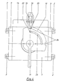
- the exemplary embodiment is the device according to the invention composed of several components.
- it is a basic body 1, two with Mounting screws 2 attached to the base body 1 Connection pieces 3 and one also with mounting screws 2 'base plate 4 fastened to the base body 1.
- Fig. 1 are in the base body 1 Sealing piston 6 acted upon on one side by a spring 5 and a sealing ring 7 and bearing 8 for receiving one Wave 9 used.
- the sealing piston 6 is in the top half of the drawing in an exonerated or in Pressure equalization position and in the lower Half of the drawing in one on a spherical Shutter body 10 shown pressed position, where to illustrate the different states the sealing element 7 in the relieved position from Shutter body 10 is shown lifted.
- the spherical closure body 10 is connected to the shaft 9 effectively connected.
- a hand lever 11 mounted on the top of the Base body 1 emerging shaft 9 .
- a disc 12 in connection with the shaft 9 is under the hand lever 11 a disc 12 as a lever guide. 2 is in the upper half of the drawing open position of the closure body 10 and in the lower half of the drawing the closed position the closure body 10 shown, wherein for Clarification of the different states that Sealing element 7 in the open position from Closure body 10 is shown raised.
- a channel (Bores 13, 13 ', 13' 'and 13' '') Sidewall 14 mounted. Two of the bores 13 and 13 ' lead continuously from the outside of the side wall 14 up to the piston annulus areas 15 and 15 'of Sealing piston 6. perpendicular to the holes 13 and 13 ' and related to them are two more Bores 13 '' and 13 '' 'arranged. The openings of the Bores 13 to 13 '' 'with the outside of the side wall 14 are sealed by screw plugs 16.
- a Shut-off valve 17 is arranged, which in its Basic position the two holes 13 '' and 13 '' ' separates from one another and into a (unspecified) recess provided in the side wall 14 is let in.
- the actuation of the shut-off valve 17 takes place by means of a lever 18 which with a spring 19 in Basic position is maintained.
- the piston annulus area 15 receives the spring 5 and is over a plurality of circumferential bores 20 with the actual line space 21 connected.
- FIG. 3 is in addition to those already described Components shown a disc guide 22. Your Function is clear in Fig. 4. Through them the Switching angle of the hand lever 11 by means of the guide path 23, which is incorporated in the disc 12, at 90 °, the respective end positions, limited.
- the disc 12 additionally has two recesses 24 into which one designed as an extension of the lever 18 and as Shift lock serving locking element 25 can snap into place.
- the Locking element 25 serves as an additional safeguard against unwanted actuation of the hand lever 11 and provides at the same time sure that the spherical Closure body only in a pressure-balanced state can be operated.
- the sealing ring 7 is from Sealing piston 6 through the piston ring area 15 located spring 5 with its spring force to the Closure body 10 pressed.
- the locking element 25 is with the recess 24 of the disc 12 in engagement.
- the lever 18 are actuated, whereby the locking element 25 from the Recess 24 of the disc 12 is released and the Hand lever 11 is switchable.
- the closure body 10 is in its closing position transferred.
- the spring 5 acts on the pressure in the line space 21 located fluid on the piston ring surface 26 of the Sealing piston 6. This makes the sealing ring 7 with a large Force pressed onto the closure body 10, whereby a reliable sealing is created.
- the on the Piston ring surfaces 26 and 27 of the sealing piston 6 acting Forces differ in their amount only by that the spring force of the spring 5 acting on the piston ring surface 26.
- the friction between the sealing ring 7 and the closure body 10 is thus only from the spring force of the spring 5th generated. This is dimensioned so that the Hand lever 11 initiated and by the shaft 9 Torque transmitted is sufficient to ensure friction between the sealing ring 7 and the closure body 10 without a large one To overcome wear in the sealing ring 7.
- the Closure body 10 can be used without great effort and without risk of shearing off the hand lever 11 from the Switch shaft 9 manually.
Landscapes
- Engineering & Computer Science (AREA)
- General Engineering & Computer Science (AREA)
- Mechanical Engineering (AREA)
- Taps Or Cocks (AREA)
- Mechanically-Actuated Valves (AREA)
- Preventing Unauthorised Actuation Of Valves (AREA)
Applications Claiming Priority (2)
| Application Number | Priority Date | Filing Date | Title |
|---|---|---|---|
| DE2001124323 DE10124323C1 (de) | 2001-05-17 | 2001-05-17 | Vorrichtung zum Absperren von Fluid durchströmten Rohrleitungen mittels einem kugelförmigen Verschlusskörper |
| DE10124323 | 2001-05-17 |
Publications (3)
| Publication Number | Publication Date |
|---|---|
| EP1258662A2 true EP1258662A2 (fr) | 2002-11-20 |
| EP1258662A3 EP1258662A3 (fr) | 2003-12-10 |
| EP1258662B1 EP1258662B1 (fr) | 2007-03-07 |
Family
ID=7685324
Family Applications (1)
| Application Number | Title | Priority Date | Filing Date |
|---|---|---|---|
| EP20020010929 Expired - Lifetime EP1258662B1 (fr) | 2001-05-17 | 2002-05-16 | Dispositif d'arrêt de fluide dans un conduit par un corps de fermeture sphérique |
Country Status (3)
| Country | Link |
|---|---|
| EP (1) | EP1258662B1 (fr) |
| DE (2) | DE10124323C1 (fr) |
| ES (1) | ES2282342T3 (fr) |
Cited By (4)
| Publication number | Priority date | Publication date | Assignee | Title |
|---|---|---|---|---|
| WO2006091117A1 (fr) * | 2005-02-28 | 2006-08-31 | Zaklad Urzadzen Gazowniczych 'gazomet' | Clapet a bille avec agencement pour separer des surfaces de joint et procede correspondant |
| CN102889394A (zh) * | 2011-07-21 | 2013-01-23 | 骆薛平 | 内释压高压软密封球阀 |
| CN104482244A (zh) * | 2014-12-24 | 2015-04-01 | 四川精控阀门制造有限公司 | 双向密封阀座结构及超低温上装式固定球阀 |
| WO2016173592A1 (fr) * | 2015-04-27 | 2016-11-03 | Schaeffler Technologies AG & Co. KG | Vanne de régulation de l'écoulement d'un fluide |
Citations (2)
| Publication number | Priority date | Publication date | Assignee | Title |
|---|---|---|---|---|
| DE2938265A1 (de) | 1979-09-21 | 1981-04-16 | M.A.N. Maschinenfabrik Augsburg-Nürnberg AG, 8500 Nürnberg | Regelbares system fuer die anpresskraft von dichtungen bei kugelhaehnen |
| DE29905414U1 (de) | 1998-03-28 | 1999-06-24 | Weinhold, Karl, Dipl.-Ing., 41464 Neuss | Kugelhahn |
Family Cites Families (7)
| Publication number | Priority date | Publication date | Assignee | Title |
|---|---|---|---|---|
| US3648970A (en) * | 1970-02-27 | 1972-03-14 | Stile Craft Mfg Inc | Handle assmebly for a rotatable ball valve |
| EP0161056A3 (fr) * | 1984-04-10 | 1988-03-16 | M & D VALVES LIMITED | Soupape sphérique |
| FR2564558B1 (fr) * | 1984-05-18 | 1986-10-03 | Vanatome | Robinet a boisseau tournant spherique |
| FR2646488B1 (fr) * | 1989-04-28 | 1991-07-26 | Vanatome | Robinet a tournant spherique |
| DE4141287C2 (de) * | 1991-12-14 | 1997-01-02 | Saarberg Hydraulik Gmbh | Kugelhahn |
| DE19544901C2 (de) * | 1995-12-01 | 2000-06-15 | Rheinauer Maschinen & Armature | Absperrvorrichtung für eine Fluidleitung, insbesondere Kugelhahn |
| DE19752591A1 (de) * | 1997-11-27 | 1999-06-02 | Borsig Gmbh | Vorrichtung zum Abdichten von in Leitungen für die Durchleitung von Flüssigkeiten oder Gasen eingebauten Absperrorganen |
-
2001
- 2001-05-17 DE DE2001124323 patent/DE10124323C1/de not_active Expired - Fee Related
-
2002
- 2002-05-16 DE DE50209627T patent/DE50209627D1/de not_active Expired - Lifetime
- 2002-05-16 ES ES02010929T patent/ES2282342T3/es not_active Expired - Lifetime
- 2002-05-16 EP EP20020010929 patent/EP1258662B1/fr not_active Expired - Lifetime
Patent Citations (2)
| Publication number | Priority date | Publication date | Assignee | Title |
|---|---|---|---|---|
| DE2938265A1 (de) | 1979-09-21 | 1981-04-16 | M.A.N. Maschinenfabrik Augsburg-Nürnberg AG, 8500 Nürnberg | Regelbares system fuer die anpresskraft von dichtungen bei kugelhaehnen |
| DE29905414U1 (de) | 1998-03-28 | 1999-06-24 | Weinhold, Karl, Dipl.-Ing., 41464 Neuss | Kugelhahn |
Cited By (6)
| Publication number | Priority date | Publication date | Assignee | Title |
|---|---|---|---|---|
| WO2006091117A1 (fr) * | 2005-02-28 | 2006-08-31 | Zaklad Urzadzen Gazowniczych 'gazomet' | Clapet a bille avec agencement pour separer des surfaces de joint et procede correspondant |
| CN102889394A (zh) * | 2011-07-21 | 2013-01-23 | 骆薛平 | 内释压高压软密封球阀 |
| CN104482244A (zh) * | 2014-12-24 | 2015-04-01 | 四川精控阀门制造有限公司 | 双向密封阀座结构及超低温上装式固定球阀 |
| CN104482244B (zh) * | 2014-12-24 | 2017-11-21 | 四川精控阀门制造有限公司 | 双向密封阀座结构及超低温上装式固定球阀 |
| WO2016173592A1 (fr) * | 2015-04-27 | 2016-11-03 | Schaeffler Technologies AG & Co. KG | Vanne de régulation de l'écoulement d'un fluide |
| US10113664B2 (en) | 2015-04-27 | 2018-10-30 | Schaeffler Technologies AG & Co. KG | Control valve for controlling a fluid flow |
Also Published As
| Publication number | Publication date |
|---|---|
| ES2282342T3 (es) | 2007-10-16 |
| EP1258662B1 (fr) | 2007-03-07 |
| EP1258662A3 (fr) | 2003-12-10 |
| DE10124323C1 (de) | 2002-12-19 |
| DE50209627D1 (de) | 2007-04-19 |
Similar Documents
| Publication | Publication Date | Title |
|---|---|---|
| EP0381069B1 (fr) | Manchon d'accouplement pour lignes d'interconnexion hydraulique | |
| DE112014003555T5 (de) | Schnellauslassventil für Schienenfahrzeuge sowie Verrohrungssystem eines Schienenfahrzeugs | |
| DE19619839C1 (de) | Hydraulikkupplung | |
| DE2631764A1 (de) | Sechsweg-umschaltventil fuer fluessigkeitsdurchstroemte rohrleitungen | |
| DE3821700C2 (fr) | ||
| DE2458236A1 (de) | Dreh-umsteuer-ventil | |
| DE10124323C1 (de) | Vorrichtung zum Absperren von Fluid durchströmten Rohrleitungen mittels einem kugelförmigen Verschlusskörper | |
| EP0843116A2 (fr) | Robinet à tournant sphérique avec un canal auxiliaire. | |
| DE19812049A1 (de) | Flüssigkeitsventil | |
| DE4411050C2 (de) | Kugelhahn | |
| DE19932139B4 (de) | Vorgesteuertes Schieberventil | |
| EP1793150B1 (fr) | Dispositif d'arrêt, notamment pour conduites sous pression | |
| DE3500907C2 (fr) | ||
| DD233402A5 (de) | Keilschieber | |
| EP1035331A2 (fr) | Distributeur piloté | |
| DE3012453C2 (de) | Durchgangsventil | |
| EP1340933B1 (fr) | Soupape haute pression | |
| DE3723673A1 (de) | Extern angesteuertes rueckschlagventil | |
| EP1182386A2 (fr) | Dispositif d'arrêt avec joint d'étanchéité | |
| EP0983442B1 (fr) | Dispositif d'actionnement a commande manuelle d'urgence | |
| DE102005033577B4 (de) | Hydraulische Ventilanordnung | |
| DE4436202A1 (de) | Kellyhahn mit doppelt gelagertem Kugelküken | |
| DD245937A1 (de) | Ventil | |
| DE2715419C2 (de) | Absperrventil, insbesondere Hochdruckabsperrventil, mit Schnellschlußmöglichkeit | |
| DE2210458A1 (de) | Drehschieber |
Legal Events
| Date | Code | Title | Description |
|---|---|---|---|
| PUAI | Public reference made under article 153(3) epc to a published international application that has entered the european phase |
Free format text: ORIGINAL CODE: 0009012 |
|
| AK | Designated contracting states |
Kind code of ref document: A2 Designated state(s): AT BE CH CY DE DK ES FI FR GB GR IE IT LI LU MC NL PT SE TR |
|
| AX | Request for extension of the european patent |
Free format text: AL;LT;LV;MK;RO;SI |
|
| PUAL | Search report despatched |
Free format text: ORIGINAL CODE: 0009013 |
|
| AK | Designated contracting states |
Kind code of ref document: A3 Designated state(s): AT BE CH CY DE DK ES FI FR GB GR IE IT LI LU MC NL PT SE TR |
|
| AX | Request for extension of the european patent |
Extension state: AL LT LV MK RO SI |
|
| 17P | Request for examination filed |
Effective date: 20031202 |
|
| 17Q | First examination report despatched |
Effective date: 20040213 |
|
| AKX | Designation fees paid |
Designated state(s): DE ES FR GB IT |
|
| GRAP | Despatch of communication of intention to grant a patent |
Free format text: ORIGINAL CODE: EPIDOSNIGR1 |
|
| GRAS | Grant fee paid |
Free format text: ORIGINAL CODE: EPIDOSNIGR3 |
|
| GRAA | (expected) grant |
Free format text: ORIGINAL CODE: 0009210 |
|
| AK | Designated contracting states |
Kind code of ref document: B1 Designated state(s): DE ES FR GB IT |
|
| REG | Reference to a national code |
Ref country code: GB Ref legal event code: FG4D Free format text: NOT ENGLISH |
|
| REF | Corresponds to: |
Ref document number: 50209627 Country of ref document: DE Date of ref document: 20070419 Kind code of ref document: P |
|
| GBT | Gb: translation of ep patent filed (gb section 77(6)(a)/1977) |
Effective date: 20070614 |
|
| REG | Reference to a national code |
Ref country code: ES Ref legal event code: FG2A Ref document number: 2282342 Country of ref document: ES Kind code of ref document: T3 |
|
| PLBE | No opposition filed within time limit |
Free format text: ORIGINAL CODE: 0009261 |
|
| STAA | Information on the status of an ep patent application or granted ep patent |
Free format text: STATUS: NO OPPOSITION FILED WITHIN TIME LIMIT |
|
| 26N | No opposition filed |
Effective date: 20071210 |
|
| REG | Reference to a national code |
Ref country code: DE Ref legal event code: R082 Ref document number: 50209627 Country of ref document: DE Representative=s name: PAUL & ALBRECHT PATENTANWALTSSOZIETAET, DE |
|
| PGFP | Annual fee paid to national office [announced via postgrant information from national office to epo] |
Ref country code: FR Payment date: 20120529 Year of fee payment: 11 Ref country code: GB Payment date: 20120522 Year of fee payment: 11 |
|
| PGFP | Annual fee paid to national office [announced via postgrant information from national office to epo] |
Ref country code: IT Payment date: 20120522 Year of fee payment: 11 |
|
| PGFP | Annual fee paid to national office [announced via postgrant information from national office to epo] |
Ref country code: ES Payment date: 20120516 Year of fee payment: 11 |
|
| PGFP | Annual fee paid to national office [announced via postgrant information from national office to epo] |
Ref country code: DE Payment date: 20130410 Year of fee payment: 12 |
|
| GBPC | Gb: european patent ceased through non-payment of renewal fee |
Effective date: 20130516 |
|
| PG25 | Lapsed in a contracting state [announced via postgrant information from national office to epo] |
Ref country code: IT Free format text: LAPSE BECAUSE OF NON-PAYMENT OF DUE FEES Effective date: 20130516 |
|
| REG | Reference to a national code |
Ref country code: FR Ref legal event code: ST Effective date: 20140131 |
|
| PG25 | Lapsed in a contracting state [announced via postgrant information from national office to epo] |
Ref country code: GB Free format text: LAPSE BECAUSE OF NON-PAYMENT OF DUE FEES Effective date: 20130516 |
|
| PG25 | Lapsed in a contracting state [announced via postgrant information from national office to epo] |
Ref country code: FR Free format text: LAPSE BECAUSE OF NON-PAYMENT OF DUE FEES Effective date: 20130531 |
|
| REG | Reference to a national code |
Ref country code: ES Ref legal event code: FD2A Effective date: 20140611 |
|
| PG25 | Lapsed in a contracting state [announced via postgrant information from national office to epo] |
Ref country code: ES Free format text: LAPSE BECAUSE OF NON-PAYMENT OF DUE FEES Effective date: 20130517 |
|
| REG | Reference to a national code |
Ref country code: DE Ref legal event code: R119 Ref document number: 50209627 Country of ref document: DE |
|
| REG | Reference to a national code |
Ref country code: DE Ref legal event code: R119 Ref document number: 50209627 Country of ref document: DE Effective date: 20141202 |
|
| PG25 | Lapsed in a contracting state [announced via postgrant information from national office to epo] |
Ref country code: DE Free format text: LAPSE BECAUSE OF NON-PAYMENT OF DUE FEES Effective date: 20141202 |