EP1258662A2 - Device for shutting off a fluid flow in a pipeline by a a ball-shaped shut-off member - Google Patents
Device for shutting off a fluid flow in a pipeline by a a ball-shaped shut-off member Download PDFInfo
- Publication number
- EP1258662A2 EP1258662A2 EP02010929A EP02010929A EP1258662A2 EP 1258662 A2 EP1258662 A2 EP 1258662A2 EP 02010929 A EP02010929 A EP 02010929A EP 02010929 A EP02010929 A EP 02010929A EP 1258662 A2 EP1258662 A2 EP 1258662A2
- Authority
- EP
- European Patent Office
- Prior art keywords
- closure body
- sealing
- piston
- pipeline
- lever
- Prior art date
- Legal status (The legal status is an assumption and is not a legal conclusion. Google has not performed a legal analysis and makes no representation as to the accuracy of the status listed.)
- Granted
Links
Images


Classifications
-
- F—MECHANICAL ENGINEERING; LIGHTING; HEATING; WEAPONS; BLASTING
- F16—ENGINEERING ELEMENTS AND UNITS; GENERAL MEASURES FOR PRODUCING AND MAINTAINING EFFECTIVE FUNCTIONING OF MACHINES OR INSTALLATIONS; THERMAL INSULATION IN GENERAL
- F16K—VALVES; TAPS; COCKS; ACTUATING-FLOATS; DEVICES FOR VENTING OR AERATING
- F16K5/00—Plug valves; Taps or cocks comprising only cut-off apparatus having at least one of the sealing faces shaped as a more or less complete surface of a solid of revolution, the opening and closing movement being predominantly rotary
- F16K5/08—Details
- F16K5/14—Special arrangements for separating the sealing faces or for pressing them together
- F16K5/20—Special arrangements for separating the sealing faces or for pressing them together for plugs with spherical surfaces
- F16K5/205—Sealing effected by the flowing medium
Definitions
- the invention relates to a device for shutting off pipelines through which fluids flow, in particular High pressure piping, at least one spherical closure body in a housing around a Axis running perpendicular to the pipeline is stored with a sealing element for sealing the spherical closure body against the pipeline.
- shut-off devices are known. So describes the German utility model 299 05 414 one generic ball valve. Such a ball valve is off a certain nominal diameter of the pipeline, for example, larger than 60 mm, and a certain one Operating pressure can no longer be used. Through the in the Pipeline prevailing pressure of the fluid becomes the ball of the ball valve strongly pressed onto the sealing ring. It there is friction between the ball and the sealing ring. Should the ball is turned back to its permeable position this frictional connection must be overcome. The the torque required for this must either be by a Lever or initiated via a transmission. That on torque that can be introduced in this way is sufficient, however Overcoming the frictional engagement is not sufficient. Also one Extending the lever cannot help. Such a ball valve can no longer work under pressure be operated.
- DE 29 38 265 A1 is a generic one Device for shutting off fluids Pipes with the features of the generic term of Claim 1 known. Also is already one Relief of the ball valve reached when turning, however with a relatively large amount of design effort by the Sealing system consists of a three-stage piston, its individual stages with different seals are sealed against the housing.
- the invention is therefore based on the object Device of the aforementioned and previously closer to design and develop the described type in such a way that actuation of the device even under pressure is reliably possible.
- valve If the valve is in the closed position of the spherical closure body is actuated, so a Pressure equalization between the end faces of the Sealing piston.
- the pressure with which the sealing ring passes through the Sealing piston on the spherical closure body is pressed by the back pressure on the opposite end face balanced and the Friction reduces, so the closure body can be rotated manually again.
- Sealing element in the open position of the device from a spring axially against the spherical Closure body is pressed. Pressing the Sealing element can also be used before the pressure is applied respectively.
- a sealing body can be used with a sealing piston connected sealing ring can be used.
- a shift lock for effective with the spherical closure body may have associated actuating lever.
- Shift lock can be, for example Act locking element.
- the shift lock can with a Lock the disc, which with the operating lever of the Closure body can be connected.
- connecting pieces for connecting the Device to be present at the pipe ends with the device can be screwed.
- the device has a modular structure having.
- the sealing piston and the sealing element can before the introduction of the spherical closure body be mounted, and the spherical closure body before installing the connectors from below into the Device can be installed.
- the exemplary embodiment is the device according to the invention composed of several components.
- it is a basic body 1, two with Mounting screws 2 attached to the base body 1 Connection pieces 3 and one also with mounting screws 2 'base plate 4 fastened to the base body 1.
- Fig. 1 are in the base body 1 Sealing piston 6 acted upon on one side by a spring 5 and a sealing ring 7 and bearing 8 for receiving one Wave 9 used.
- the sealing piston 6 is in the top half of the drawing in an exonerated or in Pressure equalization position and in the lower Half of the drawing in one on a spherical Shutter body 10 shown pressed position, where to illustrate the different states the sealing element 7 in the relieved position from Shutter body 10 is shown lifted.
- the spherical closure body 10 is connected to the shaft 9 effectively connected.
- a hand lever 11 mounted on the top of the Base body 1 emerging shaft 9 .
- a disc 12 in connection with the shaft 9 is under the hand lever 11 a disc 12 as a lever guide. 2 is in the upper half of the drawing open position of the closure body 10 and in the lower half of the drawing the closed position the closure body 10 shown, wherein for Clarification of the different states that Sealing element 7 in the open position from Closure body 10 is shown raised.
- a channel (Bores 13, 13 ', 13' 'and 13' '') Sidewall 14 mounted. Two of the bores 13 and 13 ' lead continuously from the outside of the side wall 14 up to the piston annulus areas 15 and 15 'of Sealing piston 6. perpendicular to the holes 13 and 13 ' and related to them are two more Bores 13 '' and 13 '' 'arranged. The openings of the Bores 13 to 13 '' 'with the outside of the side wall 14 are sealed by screw plugs 16.
- a Shut-off valve 17 is arranged, which in its Basic position the two holes 13 '' and 13 '' ' separates from one another and into a (unspecified) recess provided in the side wall 14 is let in.
- the actuation of the shut-off valve 17 takes place by means of a lever 18 which with a spring 19 in Basic position is maintained.
- the piston annulus area 15 receives the spring 5 and is over a plurality of circumferential bores 20 with the actual line space 21 connected.
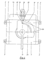
- FIG. 3 is in addition to those already described Components shown a disc guide 22. Your Function is clear in Fig. 4. Through them the Switching angle of the hand lever 11 by means of the guide path 23, which is incorporated in the disc 12, at 90 °, the respective end positions, limited.
- the disc 12 additionally has two recesses 24 into which one designed as an extension of the lever 18 and as Shift lock serving locking element 25 can snap into place.
- the Locking element 25 serves as an additional safeguard against unwanted actuation of the hand lever 11 and provides at the same time sure that the spherical Closure body only in a pressure-balanced state can be operated.
- the sealing ring 7 is from Sealing piston 6 through the piston ring area 15 located spring 5 with its spring force to the Closure body 10 pressed.
- the locking element 25 is with the recess 24 of the disc 12 in engagement.
- the lever 18 are actuated, whereby the locking element 25 from the Recess 24 of the disc 12 is released and the Hand lever 11 is switchable.
- the closure body 10 is in its closing position transferred.
- the spring 5 acts on the pressure in the line space 21 located fluid on the piston ring surface 26 of the Sealing piston 6. This makes the sealing ring 7 with a large Force pressed onto the closure body 10, whereby a reliable sealing is created.
- the on the Piston ring surfaces 26 and 27 of the sealing piston 6 acting Forces differ in their amount only by that the spring force of the spring 5 acting on the piston ring surface 26.
- the friction between the sealing ring 7 and the closure body 10 is thus only from the spring force of the spring 5th generated. This is dimensioned so that the Hand lever 11 initiated and by the shaft 9 Torque transmitted is sufficient to ensure friction between the sealing ring 7 and the closure body 10 without a large one To overcome wear in the sealing ring 7.
- the Closure body 10 can be used without great effort and without risk of shearing off the hand lever 11 from the Switch shaft 9 manually.
Abstract
Description
Die Erfindung betrifft eine Vorrichtung zum Absperren von von Fluiden durchströmten Rohrleitungen, insbesondere Hochdruckrohrleitungen, bei der wenigstens ein kugelförmiger Verschlusskörper in einem Gehäuse um eine senkrecht zur Rohrleitung verlaufende Achse drehbar gelagert ist, mit einem Dichtelement zum Abdichten des kugelförmigen Verschlusskörpers gegen die Rohrleitung.The invention relates to a device for shutting off pipelines through which fluids flow, in particular High pressure piping, at least one spherical closure body in a housing around a Axis running perpendicular to the pipeline is stored with a sealing element for sealing the spherical closure body against the pipeline.
Solche Absperrvorrichtungen sind bekannt. So beschreibt das deutsche Gebrauchsmuster 299 05 414 einen gattungsgemäßen Kugelhahn. Ein solcher Kugelhahn ist ab einer bestimmten Nennweite der Rohrleitung, beispielsweise größer 60 mm, und einem bestimmten Betriebsdruck nicht mehr verwendbar. Durch den in der Rohrleitung herrschenden Druck des Fluids wird die Kugel des Kugelhahns stark auf den Dichtring gepresst. Es entsteht Reibschluss zwischen Kugel und Dichtring. Soll die Kugel wieder in ihre durchlässige Stellung gedreht werden, muss dieser Reibschluss überwunden werden. Das hierfür notwendige Drehmoment muss entweder durch einen Hebel oder über ein Getriebe eingeleitet werden. Das auf diese Weise einleitbare Drehmoment reicht allerdings zur Überwindung des Reibschlusses nicht aus. Auch eine Verlängerung des Hebels kann keine Abhilfe schaffen. Unter Druck kann ein solcher Kugelhahn also nicht mehr betätigt werden. Such shut-off devices are known. So describes the German utility model 299 05 414 one generic ball valve. Such a ball valve is off a certain nominal diameter of the pipeline, for example, larger than 60 mm, and a certain one Operating pressure can no longer be used. Through the in the Pipeline prevailing pressure of the fluid becomes the ball of the ball valve strongly pressed onto the sealing ring. It there is friction between the ball and the sealing ring. Should the ball is turned back to its permeable position this frictional connection must be overcome. The the torque required for this must either be by a Lever or initiated via a transmission. That on torque that can be introduced in this way is sufficient, however Overcoming the frictional engagement is not sufficient. Also one Extending the lever cannot help. Such a ball valve can no longer work under pressure be operated.
Zur Lösung dieser Probleme sind bereits verschiedene konstruktive Maßnahmen unternommen worden. Beispielsweise wurde versucht, die Problematik mit einem Bypass, einem sogenanntem Hilfsdruckausgleich, zu lösen. Alle diese Konstruktionen sind allerdings in ihrer Ausführung kompliziert oder mit Nennweitenreduzierungen in den Rohrleitungen verbunden, die sich nachteilig auf die Funktion dieser bekannten Absperrvorrichtungen auswirken.There are already several to solve these problems constructive measures have been taken. For example an attempt was made to bypass the problem, a so-called auxiliary pressure equalization to solve. All these However, constructions are in their execution complicated or with nominal size reductions in the Connected pipelines that adversely affect the Function of these known shut-off devices affect.
So ist aus der DE 29 38 265 A1 eine gattungsgemäße
Vorrichtung zum Absperren von von Fluiden durchströmten
Rohrleitungen mit den Merkmalen des Oberbegriffes von
Patentanspruch 1 bekannt. Auch wird bereits eine
Entlastung des Kugelhahnes beim Drehen erreicht, jedoch
mit einem relativ großen konstruktiven Aufwand, indem das
Dichtungssystem aus einem dreistufigen Kolben besteht,
dessen einzelne Stufen mit unterschiedlichen Dichtungen
gegen das Gehäuse abgedichtet sind.DE 29 38 265 A1 is a generic one
Device for shutting off fluids
Pipes with the features of the generic term of
Der Erfindung liegt daher die Aufgabe zugrunde, eine Vorrichtung der eingangs genannten und zuvor näher beschriebenen Art so auszugestalten und weiterzubilden, dass eine Betätigung der Vorrichtung auch unter Druck zuverlässig möglich ist.The invention is therefore based on the object Device of the aforementioned and previously closer to design and develop the described type in such a way that actuation of the device even under pressure is reliably possible.
Diese Aufgabe wird bei einer Vorrichtung gemäß dem
Oberbegriff des Anspruchs 1 dadurch gelöst, dass um den
kugelförmigen Verschlusskörper herum ein beidseitig auf
seinen Stirnflächen mit Druck beaufschlagbarer, axial
verschiebbarer Dichtkolben angeordnet ist, dass zur
Abdichtung das Dichtelement mittels dem Dichtkolben auf
den kugelförmigen Verschlusskörper gepresst wird, dass
wenigstens ein Kanal die beiden Ringräume des
Dichtkolbens miteinander verbindet und mit einem
Absperrventil versehen ist. This object is achieved in a device according to the
Preamble of
Wird das Ventil in geschlossener Stellung des kugelförmigen Verschlusskörpers betätigt, so erfolgt ein Druckausgleich zwischen den Stirnflächen des Dichtkolbens. Der Druck, mit dem der Dichtring durch den Dichtkolben auf den kugelförmigen Verschlusskörper gedrückt wird, wird durch den Gegendruck auf der gegenüberliegende Stirnseite ausgeglichen und der Reibschluss reduziert, so dass der Verschlusskörper wieder manuell gedreht werden kann.If the valve is in the closed position of the spherical closure body is actuated, so a Pressure equalization between the end faces of the Sealing piston. The pressure with which the sealing ring passes through the Sealing piston on the spherical closure body is pressed by the back pressure on the opposite end face balanced and the Friction reduces, so the closure body can be rotated manually again.
Eine weitere Lehre der Erfindung sieht vor, dass das Dichtelement in geöffneter Stellung der Vorrichtung von einer Feder axial gegen den kugelförmigen Verschlusskörper gedrückt wird. Das Andrücken des Dichtelements kann auch schon vor der Druckbeaufschlagung erfolgen. Als Dichtelement für den kugelförmigen Verschlusskörper kann ein mit einem Dichtkolben verbundener Dichtring verwendet werden.Another teaching of the invention provides that Sealing element in the open position of the device from a spring axially against the spherical Closure body is pressed. Pressing the Sealing element can also be used before the pressure is applied respectively. As a sealing element for the spherical A sealing body can be used with a sealing piston connected sealing ring can be used.
In weiterer Ausführung der Erfindung kann das Absperrventil von einem Hebel betätigt werden, der gemäß einer weiteren Lehre der Erfindung eine Schaltsperre für den mit dem kugelförmigen Verschlusskörper wirksam verbundenen Betätigungshebel aufweisen kann. Bei der Schaltsperre kann es sich beispielsweise um ein Rastelement handeln. Die Schaltsperre kann mit einer Scheibe verrasten, die mit dem Betätigungshebel des Verschlusskörpers verbunden sein kann.In a further embodiment of the invention Shut-off valve operated by a lever that according to a further teaching of the invention, a shift lock for effective with the spherical closure body may have associated actuating lever. In the Shift lock can be, for example Act locking element. The shift lock can with a Lock the disc, which with the operating lever of the Closure body can be connected.
Des weiteren können Anschlussstücke zum Anschließen der Vorrichtung an Rohrleitungsenden vorhanden sein, die mit der Vorrichtung verschraubt sein können. Weiterhin ist es vorteilhaft, dass die Vorrichtung einen modularen Aufbau aufweist. Der Dichtkolben und das Dichtelement können vor dem Einbringen des kugelförmigen Verschlusskörpers montiert werden, und der kugelförmige Verschlusskörper vor der Montage der Anschlussstücke von unten in die Vorrichtung eingebaut werden.Furthermore, connecting pieces for connecting the Device to be present at the pipe ends with the device can be screwed. Furthermore it is advantageous that the device has a modular structure having. The sealing piston and the sealing element can before the introduction of the spherical closure body be mounted, and the spherical closure body before installing the connectors from below into the Device can be installed.
Die Erfindung wird nachfolgend anhand einer lediglich ein bevorzugtes Ausführungsbeispiel darstellenden Zeichnung näher erläutert. In der Zeichnung zeigen
- Fig. 1
- eine erfindungsgemäße Vorrichtung im Längsschnitt,
- Fig. 2
- die erfindungsgemäße Vorrichtung, aufgeschnitten in Draufsicht,
- Fig. 3
- die erfindungsgemäße Vorrichtung in Seitenansicht, und
- Fig. 4
- die erfindungsgemäße Vorrichtung in Draufsicht.
- Fig. 1
- a device according to the invention in longitudinal section,
- Fig. 2
- the device according to the invention, cut open in plan view,
- Fig. 3
- the device of the invention in side view, and
- Fig. 4
- the device according to the invention in plan view.
Im dargestellten und in soweit bevorzugten
Ausführungsbeispiel ist die erfindungsgemäße Vorrichtung
aus mehreren Bauelementen zusammengesetzt. Hierbei
handelt es sich um einen Grundkörper 1, zwei mit
Montageschrauben 2 am Grundkörper 1 befestigte
Anschlussstücke 3 und eine ebenfalls mit Montageschrauben
2' am Grundkörper 1 befestigte Bodenplatte 4.In the illustrated and in so far preferred
The exemplary embodiment is the device according to the invention
composed of several components. in this connection
it is a
Wie aus Fig. 1 hervorgeht, sind in den Grundkörper 1 ein
einseitig von einer Feder 5 beaufschlagter Dichtkolben 6
und ein Dichtring 7 sowie Lager 8 zur Aufnahme einer
Welle 9 eingesetzt. Der Dichtkolben 6 ist dabei in der
oberen Hälfte der Zeichnung in einer entlasteten oder im
Druckausgleich befindlichen Position und in der unteren
Hälfte der Zeichnung in einer an einen kugelförmigen
Verschlusskörper 10 angedrückten Position dargestellt,
wobei zur Verdeutlichung der unterschiedlichen Zustände
das Dichtelement 7 in der entlasteten Position vom
Verschlusskörper 10 abgehoben dargestellt ist.As is apparent from Fig. 1, are in the
Der kugelförmige Verschlusskörper 10 ist mit der Welle 9
wirksam verbunden. Auf der im oberen Bereich aus dem
Grundkörper 1 heraustretenden Welle 9 ist ein Handhebel
11 montiert. In Verbindung mit der Welle 9 befindet sich
unter dem Handhebel 11 eine Scheibe 12 als Hebelführung.
In Fig. 2 ist in der oberen Hälfte der Zeichnung die
geöffnete Stellung des Verschlusskörpers 10 und in der
unteren Hälfte der Zeichnung die geschlossene Stellung
des Verschlusskörpers 10 dargestellt, wobei zur
Verdeutlichung der unterschiedlichen Zustände das
Dichtelement 7 in der geöffneten Stellung vom
Verschlusskörper 10 abgehoben wiedergegeben ist.The
Zwischen den Anschlussstücken 3 ist eine einen Kanal
(Bohrungen 13, 13', 13'' und 13''') aufweisende
Seitenwand 14 montiert. Zwei der Bohrungen 13 und 13'
führen von der Außenseite der Seitenwand 14 durchgängig
bis zu den Kolbenringraumbereichen 15 und 15' des
Dichtkolbens 6. Rechtwinklig zu den Bohrungen 13 und 13'
und mit ihnen in Verbindung stehend sind zwei weitere
Bohrungen 13'' und 13''' angeordnet. Die Öffnungen der
Bohrungen 13 bis 13''' mit den Außenseiten der Seitenwand
14 sind durch Verschlussschrauben 16 abgedichtet.
Zwischen den Bohrungen 13'' und 13''' ist ein
Absperrventil 17 angeordnet, welches in seiner
Grundstellung die beiden Bohrungen 13'' und 13'''
voneinander trennt und in eine (nicht näher bezeichnete)
dafür vorgesehene Aussparung in der Seitenwand 14
eingelassen ist. Die Betätigung des Absperrventils 17
erfolgt mittels einem Hebel 18, der mit einer Feder 19 in
Grundstellung gehalten wird.Between the
Der Kolbenringraumbereich 15 nimmt die Feder 5 auf und
ist über eine Mehrzahl umlaufender Bohrungen 20 mit dem
eigentlichen Leitungsraum 21 verbunden.The
In Fig. 3 ist zusätzlich zu den schon beschriebenen
Bauteilen eine Scheibenführung 22 dargestellt. Ihre
Funktion wird in Fig. 4 deutlich. Durch sie wird der
Schaltwinkel des Handhebels 11 mittels dem Führungsweg
23, der in der Scheibe 12 eingearbeitet ist, auf 90°, die
jeweiligen Endstellungen, beschränkt. Die Scheibe 12
weist zusätzlich zwei Ausnehmungen 24 auf, in welche ein
als Verlängerung des Hebels 18 ausgestaltetes und als
Schaltsperre dienendes Rastelement 25 einrasten kann. Das
Rastelement 25 dient als zusätzliche Sicherung gegen
ungewolltes Betätigen des Handhebels 11 und stellt
gleichzeitig sicher, dass der kugelförmige
Verschlusskörper nur im druckausgeglichenen Zustand
betätigt werden kann.3 is in addition to those already described
Components shown a
Ist die erfindungsgemäße Vorrichtung in eine mit Druck
beaufschlagte Rohrleitung eingebaut, so fließt in
geöffneter Stellung des Verschlusskörpers 10 das Fluid
durch den Leitungsraum 21. Der Dichtring 7 wird vom
Dichtkolben 6 durch die im Kolbenringraumbereich 15
befindliche Feder 5 mit ihrer Federkraft an den
Verschlusskörper 10 angedrückt. Das Rastelement 25 steht
mit der Ausnehmung 24 der Scheibe 12 im Eingriff. Soll
die erfindungsgemäße Vorrichtung durch Betätigung des
Handhebels 11 verschlossen werden, so muss der Hebel 18
betätigt werden, wodurch das Rastelement 25 aus der
Ausnehmung 24 der Scheibe 12 gelöst wird und der
Handhebel 11 schaltbar wird. Durch Drehen des Handhebels
11 um 90° wird der Verschlusskörper 10 in seine
schließende Position überführt. Zusätzlich zur Federkraft
der Feder 5 wirkt der Druck des im Leitungsraum 21
befindlichen Fluids auf die Kolbenringfläche 26 des
Dichtkolbens 6. Dadurch wird der Dichtring 7 mit großer
Kraft auf den Verschlusskörper 10 gepresst, wodurch eine
zuverlässige Abdichtung entsteht.Is the device according to the invention in one with pressure
pressurized pipeline installed, flows into
open position of the
Nach Beendigung des Schaltvorgangs befindet sich das
Rastelement 25 mit der zweiten Ausnehmung 24 der Scheibe
12 im Eingriff. Der Reibschluss zwischen Dichtring 7 und
Verschlusskörper 10 ist jetzt so groß, dass durch bloßes
Betätigen des Handhebels 11 der Verschlusskörper 10 nicht
wieder in die geöffnete Position überführt werden kann.After the switching process is complete, that is
Locking
Soll die erfindungsgemäße Vorrichtung wieder geöffnet
werden, also der Verschlusskörper 10 wieder in seine
geöffnete Position überführt werden, muss die Intensität
des Reibschlusses zwischen Dichtring 7 und
Verschlusskörper 10 reduziert werden. Dieses geschieht,
indem über die Beaufschlagung der der Kolbenringfläche 26
gegenüberliegenden (gleich großen) Kolbenringfläche 27
ein Druckausgleich hergestellt wird. Die Bohrungen 13 bis
13''' sind ebenso wie der Kolbenringraumbereich 15'
bereits mit Fluid gefüllt. Der Kolbenringraumbereich 15
und die Bohrungen 13 und 13'' stehen bereits unter dem in
der Rohrleitung herrschenden Druck. Durch Betätigen des
Hebels 18 werden die Bohrungen 13' und 13'' und der
Kolbenringraumbereich 15' ebenfalls mit dem im Rohrraum
21 herrschenden Druck beaufschlagt. Die auf die
Kolbenringflächen 26 und 27 des Dichtkolbens 6 wirkenden
Kräfte unterscheiden sich in ihrem Betrag nur um die auf
die Kolbenringfläche 26 wirkende Federkraft der Feder 5.
Die Reibung zwischen Dichtring 7 und dem Verschlusskörper
10 wird somit nur noch von der Federkraft der Feder 5
erzeugt. Diese ist so dimensioniert, dass das durch den
Handhebel 11 eingeleitete und durch die Welle 9
übertragene Drehmoment ausreicht, um den Reibschluss
zwischen Dichtring 7 und Verschlusskörper 10 ohne großen
Verschleiß im Dichtring 7 zu überwinden. Der
Verschlusskörper 10 lässt sich ohne großen Kraftaufwand
und ohne Gefahr des Abscherens des Handhebels 11 von der
Welle 9 manuell schalten.If the device according to the invention is to be opened again
are, so the
Claims (7)
dadurch gekennzeichnet, dass die Flächen des Dichtkolbens (6) Stirnflächen (26, 27)sind, dass wenigstens ein Kanal die beiden Ringräume (15, 15') des Dichtkolbens (6) miteinander verbindet und mit einem Absperrventil (17) versehen ist.Device for shutting off pipelines through which fluids flow, in particular high-pressure pipelines, in which at least one spherical closure body (10) is rotatably mounted in a housing about an axis running perpendicular to the pipeline, with a sealing element for sealing the spherical closure body (10) against the pipeline, wherein an axially displaceable sealing piston (6), which can be pressurized on surfaces on both sides, is arranged around the spherical closure body (10), that the sealing element (7) is pressed onto the spherical closure body (10) by means of the sealing piston (6),
characterized in that the surfaces of the sealing piston (6) are end faces (26, 27), that at least one channel connects the two annular spaces (15, 15 ') of the sealing piston (6) to one another and is provided with a shut-off valve (17).
dadurch gekennzeichnet, dass das Dichtelement (7) in geöffneter Stellung der Vorrichtung von einer Feder (5) axial gegen den kugelförmigen Verschlusskörper (10) gedrückt wird. Device according to claim 1,
characterized in that the sealing element (7) in the open position of the device is pressed axially by a spring (5) against the spherical closure body (10).
dadurch gekennzeichnet, dass das Absperrventil (17) von einem Hebel (18) betätigt wird.Device according to claim 1 or 2,
characterized in that the shut-off valve (17) is actuated by a lever (18).
dadurch gekennzeichnet, dass der Hebel (18) eine Schaltsperre (25) für den mit dem kugelförmigen Verschlusskörper (10) wirksam verbundenen Betätigungshebel (11) aufweist.Device according to claim 3,
characterized in that the lever (18) has a shift lock (25) for the actuating lever (11) which is operatively connected to the spherical closure body (10).
dadurch gekennzeichnet, dass die Schaltsperre (25) in eine mit dem Betätigungshebel (11) des Verschlusskörpers (10) verbundene Scheibe (12) verrastbar ist.Device according to claim 4,
characterized in that the shift lock (25) can be latched into a disc (12) connected to the actuating lever (11) of the closure body (10).
dadurch gekennzeichnet,dass Anschlussstücke (3) zum Anschließen der Vorrichtung an Rohrleitungsenden vorhanden sind und dass die Anschlussstücke (3) mit der Vorrichtung verschraubt sind.Device according to one of claims 1 to 5,
characterized in that there are connecting pieces (3) for connecting the device to pipe ends and that the connecting pieces (3) are screwed to the device.
dadurch gekennzeichnet, dass die Vorrichtung einen modularen Aufbau aufweist.Device according to one of claims 1 to 6,
characterized in that the device has a modular structure.
Applications Claiming Priority (2)
| Application Number | Priority Date | Filing Date | Title |
|---|---|---|---|
| DE10124323 | 2001-05-17 | ||
| DE2001124323 DE10124323C1 (en) | 2001-05-17 | 2001-05-17 | Device for shutting off pipelines through which fluid flows by means of a spherical closure body |
Publications (3)
| Publication Number | Publication Date |
|---|---|
| EP1258662A2 true EP1258662A2 (en) | 2002-11-20 |
| EP1258662A3 EP1258662A3 (en) | 2003-12-10 |
| EP1258662B1 EP1258662B1 (en) | 2007-03-07 |
Family
ID=7685324
Family Applications (1)
| Application Number | Title | Priority Date | Filing Date |
|---|---|---|---|
| EP20020010929 Expired - Lifetime EP1258662B1 (en) | 2001-05-17 | 2002-05-16 | Device for shutting off a fluid flow in a pipeline by a a ball-shaped shut-off member |
Country Status (3)
| Country | Link |
|---|---|
| EP (1) | EP1258662B1 (en) |
| DE (2) | DE10124323C1 (en) |
| ES (1) | ES2282342T3 (en) |
Cited By (4)
| Publication number | Priority date | Publication date | Assignee | Title |
|---|---|---|---|---|
| WO2006091117A1 (en) * | 2005-02-28 | 2006-08-31 | Zaklad Urzadzen Gazowniczych 'gazomet' | Ball valve with arrangement for separating sealing surfaces and corresponding method |
| CN102889394A (en) * | 2011-07-21 | 2013-01-23 | 骆薛平 | Inward depressurizing high pressure soft sealing ball valve |
| CN104482244A (en) * | 2014-12-24 | 2015-04-01 | 四川精控阀门制造有限公司 | Bidirectional sealing valve seat structure and ultralow temperature top-assembled fixed ball valve |
| WO2016173592A1 (en) * | 2015-04-27 | 2016-11-03 | Schaeffler Technologies AG & Co. KG | Control valve for controlling a fluid flow |
Citations (2)
| Publication number | Priority date | Publication date | Assignee | Title |
|---|---|---|---|---|
| DE2938265A1 (en) | 1979-09-21 | 1981-04-16 | M.A.N. Maschinenfabrik Augsburg-Nürnberg AG, 8500 Nürnberg | Pipe line coupling with controlled seal pressure - has triple piston with floating seal |
| DE29905414U1 (en) | 1998-03-28 | 1999-06-24 | Weinhold Karl | Ball valve |
Family Cites Families (7)
| Publication number | Priority date | Publication date | Assignee | Title |
|---|---|---|---|---|
| US3648970A (en) * | 1970-02-27 | 1972-03-14 | Stile Craft Mfg Inc | Handle assmebly for a rotatable ball valve |
| EP0161056A3 (en) * | 1984-04-10 | 1988-03-16 | M & D VALVES LIMITED | Ball valve |
| FR2564558B1 (en) * | 1984-05-18 | 1986-10-03 | Vanatome | SPHERICAL ROTATING BALL VALVE |
| FR2646488B1 (en) * | 1989-04-28 | 1991-07-26 | Vanatome | SPHERICAL ROTARY TAP |
| DE4141287C2 (en) * | 1991-12-14 | 1997-01-02 | Saarberg Hydraulik Gmbh | Ball valve |
| DE19544901C2 (en) * | 1995-12-01 | 2000-06-15 | Rheinauer Maschinen & Armature | Shut-off device for a fluid line, in particular a ball valve |
| DE19752591A1 (en) * | 1997-11-27 | 1999-06-02 | Borsig Gmbh | Device for sealing shut-off devices installed in lines for the passage of liquids or gases |
-
2001
- 2001-05-17 DE DE2001124323 patent/DE10124323C1/en not_active Expired - Fee Related
-
2002
- 2002-05-16 DE DE50209627T patent/DE50209627D1/en not_active Expired - Lifetime
- 2002-05-16 EP EP20020010929 patent/EP1258662B1/en not_active Expired - Lifetime
- 2002-05-16 ES ES02010929T patent/ES2282342T3/en not_active Expired - Lifetime
Patent Citations (2)
| Publication number | Priority date | Publication date | Assignee | Title |
|---|---|---|---|---|
| DE2938265A1 (en) | 1979-09-21 | 1981-04-16 | M.A.N. Maschinenfabrik Augsburg-Nürnberg AG, 8500 Nürnberg | Pipe line coupling with controlled seal pressure - has triple piston with floating seal |
| DE29905414U1 (en) | 1998-03-28 | 1999-06-24 | Weinhold Karl | Ball valve |
Cited By (6)
| Publication number | Priority date | Publication date | Assignee | Title |
|---|---|---|---|---|
| WO2006091117A1 (en) * | 2005-02-28 | 2006-08-31 | Zaklad Urzadzen Gazowniczych 'gazomet' | Ball valve with arrangement for separating sealing surfaces and corresponding method |
| CN102889394A (en) * | 2011-07-21 | 2013-01-23 | 骆薛平 | Inward depressurizing high pressure soft sealing ball valve |
| CN104482244A (en) * | 2014-12-24 | 2015-04-01 | 四川精控阀门制造有限公司 | Bidirectional sealing valve seat structure and ultralow temperature top-assembled fixed ball valve |
| CN104482244B (en) * | 2014-12-24 | 2017-11-21 | 四川精控阀门制造有限公司 | Formula fixing ball valve is filled on two way seal valve seat construction and ultralow temperature |
| WO2016173592A1 (en) * | 2015-04-27 | 2016-11-03 | Schaeffler Technologies AG & Co. KG | Control valve for controlling a fluid flow |
| US10113664B2 (en) | 2015-04-27 | 2018-10-30 | Schaeffler Technologies AG & Co. KG | Control valve for controlling a fluid flow |
Also Published As
| Publication number | Publication date |
|---|---|
| EP1258662A3 (en) | 2003-12-10 |
| EP1258662B1 (en) | 2007-03-07 |
| DE50209627D1 (en) | 2007-04-19 |
| ES2282342T3 (en) | 2007-10-16 |
| DE10124323C1 (en) | 2002-12-19 |
Similar Documents
| Publication | Publication Date | Title |
|---|---|---|
| EP0381069B1 (en) | Coupling sleeve for hydraulic connection lines | |
| DE3000619A1 (en) | LEVER-OPERATED COUPLING FOR PRESSURE MEDIUM PIPES | |
| DE112014003555T5 (en) | Quick-release valve for rail vehicles and piping system of a rail vehicle | |
| DE19619839C1 (en) | Coupling for connecting hydraulic conduits | |
| DE2631764A1 (en) | SIX-WAY SWITCHING VALVE FOR LIQUID THROUGH PIPES | |
| DE3821700C2 (en) | ||
| DE2458236A1 (en) | ROTARY CHANGEOVER VALVE | |
| DE10124323C1 (en) | Device for shutting off pipelines through which fluid flows by means of a spherical closure body | |
| EP0843116A2 (en) | Ball valve with additional flow line | |
| DE19812049A1 (en) | Liquid valve | |
| DE4411050C2 (en) | ball valve | |
| DE2237239C3 (en) | Drill string valve | |
| DE19932139B4 (en) | Pilot operated slide valve | |
| EP1793150B1 (en) | Shut-off device, in particular for pressure conduits | |
| DE3500907C2 (en) | ||
| EP1035331A2 (en) | Pilot-operated multiway valve | |
| DE3012453C2 (en) | Straight-way valve | |
| EP1340933B1 (en) | High pressure valve | |
| DE3723673A1 (en) | Externally controlled non-return valve | |
| DD233402A5 (en) | WEDGE SLIDE | |
| EP1182386A2 (en) | Shut-off device with sealing | |
| EP0983442B1 (en) | Manually operated emergency control actuation device | |
| DE102005033577B4 (en) | Hydraulic valve arrangement | |
| DE4436202A1 (en) | Ball valve mounted within the drill string, can be turned under high pressure by hand | |
| DD245937A1 (en) | VALVE |
Legal Events
| Date | Code | Title | Description |
|---|---|---|---|
| PUAI | Public reference made under article 153(3) epc to a published international application that has entered the european phase |
Free format text: ORIGINAL CODE: 0009012 |
|
| AK | Designated contracting states |
Kind code of ref document: A2 Designated state(s): AT BE CH CY DE DK ES FI FR GB GR IE IT LI LU MC NL PT SE TR |
|
| AX | Request for extension of the european patent |
Free format text: AL;LT;LV;MK;RO;SI |
|
| PUAL | Search report despatched |
Free format text: ORIGINAL CODE: 0009013 |
|
| AK | Designated contracting states |
Kind code of ref document: A3 Designated state(s): AT BE CH CY DE DK ES FI FR GB GR IE IT LI LU MC NL PT SE TR |
|
| AX | Request for extension of the european patent |
Extension state: AL LT LV MK RO SI |
|
| 17P | Request for examination filed |
Effective date: 20031202 |
|
| 17Q | First examination report despatched |
Effective date: 20040213 |
|
| AKX | Designation fees paid |
Designated state(s): DE ES FR GB IT |
|
| GRAP | Despatch of communication of intention to grant a patent |
Free format text: ORIGINAL CODE: EPIDOSNIGR1 |
|
| GRAS | Grant fee paid |
Free format text: ORIGINAL CODE: EPIDOSNIGR3 |
|
| GRAA | (expected) grant |
Free format text: ORIGINAL CODE: 0009210 |
|
| AK | Designated contracting states |
Kind code of ref document: B1 Designated state(s): DE ES FR GB IT |
|
| REG | Reference to a national code |
Ref country code: GB Ref legal event code: FG4D Free format text: NOT ENGLISH |
|
| REF | Corresponds to: |
Ref document number: 50209627 Country of ref document: DE Date of ref document: 20070419 Kind code of ref document: P |
|
| GBT | Gb: translation of ep patent filed (gb section 77(6)(a)/1977) |
Effective date: 20070614 |
|
| REG | Reference to a national code |
Ref country code: ES Ref legal event code: FG2A Ref document number: 2282342 Country of ref document: ES Kind code of ref document: T3 |
|
| PLBE | No opposition filed within time limit |
Free format text: ORIGINAL CODE: 0009261 |
|
| STAA | Information on the status of an ep patent application or granted ep patent |
Free format text: STATUS: NO OPPOSITION FILED WITHIN TIME LIMIT |
|
| 26N | No opposition filed |
Effective date: 20071210 |
|
| REG | Reference to a national code |
Ref country code: DE Ref legal event code: R082 Ref document number: 50209627 Country of ref document: DE Representative=s name: PAUL & ALBRECHT PATENTANWALTSSOZIETAET, DE |
|
| PGFP | Annual fee paid to national office [announced via postgrant information from national office to epo] |
Ref country code: FR Payment date: 20120529 Year of fee payment: 11 Ref country code: GB Payment date: 20120522 Year of fee payment: 11 |
|
| PGFP | Annual fee paid to national office [announced via postgrant information from national office to epo] |
Ref country code: IT Payment date: 20120522 Year of fee payment: 11 |
|
| PGFP | Annual fee paid to national office [announced via postgrant information from national office to epo] |
Ref country code: ES Payment date: 20120516 Year of fee payment: 11 |
|
| PGFP | Annual fee paid to national office [announced via postgrant information from national office to epo] |
Ref country code: DE Payment date: 20130410 Year of fee payment: 12 |
|
| GBPC | Gb: european patent ceased through non-payment of renewal fee |
Effective date: 20130516 |
|
| PG25 | Lapsed in a contracting state [announced via postgrant information from national office to epo] |
Ref country code: IT Free format text: LAPSE BECAUSE OF NON-PAYMENT OF DUE FEES Effective date: 20130516 |
|
| REG | Reference to a national code |
Ref country code: FR Ref legal event code: ST Effective date: 20140131 |
|
| PG25 | Lapsed in a contracting state [announced via postgrant information from national office to epo] |
Ref country code: GB Free format text: LAPSE BECAUSE OF NON-PAYMENT OF DUE FEES Effective date: 20130516 |
|
| PG25 | Lapsed in a contracting state [announced via postgrant information from national office to epo] |
Ref country code: FR Free format text: LAPSE BECAUSE OF NON-PAYMENT OF DUE FEES Effective date: 20130531 |
|
| REG | Reference to a national code |
Ref country code: ES Ref legal event code: FD2A Effective date: 20140611 |
|
| PG25 | Lapsed in a contracting state [announced via postgrant information from national office to epo] |
Ref country code: ES Free format text: LAPSE BECAUSE OF NON-PAYMENT OF DUE FEES Effective date: 20130517 |
|
| REG | Reference to a national code |
Ref country code: DE Ref legal event code: R119 Ref document number: 50209627 Country of ref document: DE |
|
| REG | Reference to a national code |
Ref country code: DE Ref legal event code: R119 Ref document number: 50209627 Country of ref document: DE Effective date: 20141202 |
|
| PG25 | Lapsed in a contracting state [announced via postgrant information from national office to epo] |
Ref country code: DE Free format text: LAPSE BECAUSE OF NON-PAYMENT OF DUE FEES Effective date: 20141202 |