EP1257445B1 - Wischblatt zum reinigen von scheiben von kraftfahrzeugen - Google Patents
Wischblatt zum reinigen von scheiben von kraftfahrzeugen Download PDFInfo
- Publication number
- EP1257445B1 EP1257445B1 EP01905804A EP01905804A EP1257445B1 EP 1257445 B1 EP1257445 B1 EP 1257445B1 EP 01905804 A EP01905804 A EP 01905804A EP 01905804 A EP01905804 A EP 01905804A EP 1257445 B1 EP1257445 B1 EP 1257445B1
- Authority
- EP
- European Patent Office
- Prior art keywords
- wiper
- wiper blade
- strip
- cover
- lip
- Prior art date
- Legal status (The legal status is an assumption and is not a legal conclusion. Google has not performed a legal analysis and makes no representation as to the accuracy of the status listed.)
- Expired - Lifetime
Links
- 238000004140 cleaning Methods 0.000 title claims description 4
- 229920003023 plastic Polymers 0.000 claims description 13
- 239000004033 plastic Substances 0.000 claims description 13
- 239000012528 membrane Substances 0.000 claims description 12
- 239000000463 material Substances 0.000 claims description 7
- 239000011521 glass Substances 0.000 claims 5
- 230000000717 retained effect Effects 0.000 claims 4
- 229920002457 flexible plastic Polymers 0.000 claims 1
- 238000011161 development Methods 0.000 description 10
- 230000018109 developmental process Effects 0.000 description 10
- 230000002349 favourable effect Effects 0.000 description 8
- 238000003780 insertion Methods 0.000 description 8
- 230000037431 insertion Effects 0.000 description 8
- 229910000831 Steel Inorganic materials 0.000 description 4
- 208000027418 Wounds and injury Diseases 0.000 description 4
- 230000006378 damage Effects 0.000 description 4
- 230000000694 effects Effects 0.000 description 4
- 239000013013 elastic material Substances 0.000 description 4
- 238000001746 injection moulding Methods 0.000 description 4
- 208000014674 injury Diseases 0.000 description 4
- 239000002184 metal Substances 0.000 description 4
- 238000003825 pressing Methods 0.000 description 4
- 230000000087 stabilizing effect Effects 0.000 description 4
- 239000010959 steel Substances 0.000 description 4
- 239000000725 suspension Substances 0.000 description 4
- 238000010276 construction Methods 0.000 description 3
- 241001295925 Gegenes Species 0.000 description 2
- 229910000639 Spring steel Inorganic materials 0.000 description 2
- 239000011248 coating agent Substances 0.000 description 2
- 238000000576 coating method Methods 0.000 description 2
- 238000013461 design Methods 0.000 description 2
- 230000006866 deterioration Effects 0.000 description 2
- 238000009826 distribution Methods 0.000 description 2
- 230000007613 environmental effect Effects 0.000 description 2
- 230000003287 optical effect Effects 0.000 description 2
- 230000008092 positive effect Effects 0.000 description 2
- 238000004080 punching Methods 0.000 description 2
- 230000002787 reinforcement Effects 0.000 description 2
- 238000003860 storage Methods 0.000 description 2
- 238000012549 training Methods 0.000 description 2
- XLYOFNOQVPJJNP-UHFFFAOYSA-N water Substances O XLYOFNOQVPJJNP-UHFFFAOYSA-N 0.000 description 2
- 230000007812 deficiency Effects 0.000 description 1
- 238000012360 testing method Methods 0.000 description 1
Images

Classifications
-
- B—PERFORMING OPERATIONS; TRANSPORTING
- B60—VEHICLES IN GENERAL
- B60S—SERVICING, CLEANING, REPAIRING, SUPPORTING, LIFTING, OR MANOEUVRING OF VEHICLES, NOT OTHERWISE PROVIDED FOR
- B60S1/00—Cleaning of vehicles
- B60S1/02—Cleaning windscreens, windows or optical devices
- B60S1/04—Wipers or the like, e.g. scrapers
- B60S1/32—Wipers or the like, e.g. scrapers characterised by constructional features of wiper blade arms or blades
- B60S1/38—Wiper blades
- B60S1/3848—Flat-type wiper blade, i.e. without harness
- B60S1/3874—Flat-type wiper blade, i.e. without harness with a reinforcing vertebra
- B60S1/3875—Flat-type wiper blade, i.e. without harness with a reinforcing vertebra rectangular section
-
- B—PERFORMING OPERATIONS; TRANSPORTING
- B60—VEHICLES IN GENERAL
- B60S—SERVICING, CLEANING, REPAIRING, SUPPORTING, LIFTING, OR MANOEUVRING OF VEHICLES, NOT OTHERWISE PROVIDED FOR
- B60S1/00—Cleaning of vehicles
- B60S1/02—Cleaning windscreens, windows or optical devices
- B60S1/04—Wipers or the like, e.g. scrapers
- B60S1/32—Wipers or the like, e.g. scrapers characterised by constructional features of wiper blade arms or blades
- B60S1/38—Wiper blades
- B60S1/3806—Means, or measures taken, for influencing the aerodynamic quality of the wiper blades
- B60S1/381—Spoilers mounted on the squeegee or on the vertebra
-
- B—PERFORMING OPERATIONS; TRANSPORTING
- B60—VEHICLES IN GENERAL
- B60S—SERVICING, CLEANING, REPAIRING, SUPPORTING, LIFTING, OR MANOEUVRING OF VEHICLES, NOT OTHERWISE PROVIDED FOR
- B60S1/00—Cleaning of vehicles
- B60S1/02—Cleaning windscreens, windows or optical devices
- B60S1/04—Wipers or the like, e.g. scrapers
- B60S1/32—Wipers or the like, e.g. scrapers characterised by constructional features of wiper blade arms or blades
- B60S1/38—Wiper blades
- B60S1/3848—Flat-type wiper blade, i.e. without harness
- B60S1/3874—Flat-type wiper blade, i.e. without harness with a reinforcing vertebra
- B60S1/3875—Flat-type wiper blade, i.e. without harness with a reinforcing vertebra rectangular section
- B60S1/3879—Flat-type wiper blade, i.e. without harness with a reinforcing vertebra rectangular section placed in side grooves in the squeegee
-
- B—PERFORMING OPERATIONS; TRANSPORTING
- B60—VEHICLES IN GENERAL
- B60S—SERVICING, CLEANING, REPAIRING, SUPPORTING, LIFTING, OR MANOEUVRING OF VEHICLES, NOT OTHERWISE PROVIDED FOR
- B60S1/00—Cleaning of vehicles
- B60S1/02—Cleaning windscreens, windows or optical devices
- B60S1/04—Wipers or the like, e.g. scrapers
- B60S1/32—Wipers or the like, e.g. scrapers characterised by constructional features of wiper blade arms or blades
- B60S1/38—Wiper blades
- B60S1/3806—Means, or measures taken, for influencing the aerodynamic quality of the wiper blades
-
- B—PERFORMING OPERATIONS; TRANSPORTING
- B60—VEHICLES IN GENERAL
- B60S—SERVICING, CLEANING, REPAIRING, SUPPORTING, LIFTING, OR MANOEUVRING OF VEHICLES, NOT OTHERWISE PROVIDED FOR
- B60S1/00—Cleaning of vehicles
- B60S1/02—Cleaning windscreens, windows or optical devices
- B60S1/04—Wipers or the like, e.g. scrapers
- B60S1/32—Wipers or the like, e.g. scrapers characterised by constructional features of wiper blade arms or blades
- B60S1/38—Wiper blades
- B60S2001/3812—Means of supporting or holding the squeegee or blade rubber
- B60S2001/3817—Means of supporting or holding the squeegee or blade rubber chacterised by a backing strip to aid mounting of squeegee in support
- B60S2001/3818—Means of supporting or holding the squeegee or blade rubber chacterised by a backing strip to aid mounting of squeegee in support the backing strip being a channel-like element, e.g. not continuous
-
- B—PERFORMING OPERATIONS; TRANSPORTING
- B60—VEHICLES IN GENERAL
- B60S—SERVICING, CLEANING, REPAIRING, SUPPORTING, LIFTING, OR MANOEUVRING OF VEHICLES, NOT OTHERWISE PROVIDED FOR
- B60S1/00—Cleaning of vehicles
- B60S1/02—Cleaning windscreens, windows or optical devices
- B60S1/04—Wipers or the like, e.g. scrapers
- B60S1/32—Wipers or the like, e.g. scrapers characterised by constructional features of wiper blade arms or blades
- B60S1/38—Wiper blades
- B60S2001/3812—Means of supporting or holding the squeegee or blade rubber
- B60S2001/3817—Means of supporting or holding the squeegee or blade rubber chacterised by a backing strip to aid mounting of squeegee in support
- B60S2001/382—Means of supporting or holding the squeegee or blade rubber chacterised by a backing strip to aid mounting of squeegee in support the backing strip being an essentially planar reinforcing strip, e.g. vertebra
Definitions
- the invention relates to a wiper blade for a Wiper device for wiping windows of vehicles with a squeegee, which is a wiper lip facing the disc one of the disc facing away back and one Has wiper lip with the rear part connecting tilting web
- the wiper blade further includes a squeegee stabilizing, band-like, elastic carrying element on, which with a transverse to the longitudinal extent of Wischblattes drivable, to the wheel loadable wiper arm is connectable.
- the support element and the Back part partially surrounding element provided, which in parallel to the disk, on the longitudinal extent of the Wiper blade directed view, the flow direction corresponds, covers the tilting bridge.
- Wiper blades have become known from DE 299 03 123 U1.
- the one resilient insert with a tube-like have elastomeric enclosure, in which a squeegee is used.
- wiper blades to the Carrying element over the entire swept by the wiper blade Wiping field of the disc as evenly as possible distribution of the wiper blade outgoing wiper blade contact pressure at the Ensure disc.
- the support element points to it advantageously a suitable pre-bend on to a required, uniform wiper blade contact pressure against to reach the disc.
- the elaborate mounting bracket construction with two in the Wiper strip arranged spring rails replaced as they are conventional wiper blades is practiced and For example, from DE 15 053 97 A1 is known.
- the generic, known wiper blades have the disadvantage that they have a complex structure exhibit.
- Such a wiper blade looks next to the Carrying element arranged transversely to the support element Querologicaln, arranged in the support element recesses and in the squeegee existing grooves for receiving the surrounding the support member at least in sections Sheath on.
- Such a structure of the wiper blade leads to a not insignificant height, which in Driving brings great disadvantages. For example provides the side of the wiper blade facing the airstream a fairly large attack surface for the wiper blade impending wind. It also builds on the one of the Windward side facing away from the wiper blade considerable negative pressure.
- wiper blades consisting essentially of a wiper strip and at least one connected to this wiper strip Consist of spring rail.
- wiper blades have the disadvantage that the protruding spring rails to a high degree disturbing Noise, especially through the wind, generate and also pose a source of injury.
- a wiper blade is known in which the wiper is provided with two lateral grooves.
- These grooves are used spring rails, which in turn of a wraparound enclosing the wiper strip held become.
- the grooves do not form in this embodiment Tilting bridge around which the wiper lip can tilt. Therefore, the Cover also no Kippsteg cover.
- GB-A-2 346 318 also has the wiper strip no Kippsteg.
- the Wischleise molded grooves are spring rails and bent longitudinal edges of the wiper strip encompassing Cover inserted. A tilting of the wiper lip is not possible. Therefore, the grooves produce no Kippsteg.
- the object of the invention is to show a wiper blade, which while maintaining the basic advantages of a known wiper blade has improved properties.
- the casing is streamlined, and in the longitudinal extent of the wiper blade it encloses completely the carrying element and the back part and covers the the wiper strip facing away from the top of the back part.
- the flow direction corresponds, covers the shroud off the tipping.
- Such a wiper blade has in particular the advantage that it can be designed very flat and only a very low attack surface for the airstream forms.
- the carrying element, the back part as well as in particular also the tilting edge is covered by the sheathing, offers itself for the impact on the wiper blade, approximately to Disc parallel flow of the wind a very small Attack.
- Wiper blade has a very low overall weight and good can be mounted.
- the covers Sheath also facing away from the disc part of the Wiper lip off. This makes the wiper blade even flatter and a even more favorable flow behavior of the wiper blade be achieved.
- the sheathing a largely having elliptical cross-section.
- a elliptical cross section has a relatively small Flow resistance on.
- a elliptical cross section of the wiper strip according to the invention be made very flat.
- the sheath at least partially a surface structuring to reduce the Air resistance on. This will make it even better Wiping behavior of the wiper blade according to the invention achieved.
- the Sheath on the windward side of a turbulator is intended, also a create turbulent boundary layer, which positive Effects on the wiping behavior of the invention Wiper blade has.
- the Wiper strip with tilting bar in orthogonal to the pane extending direction resiliently arranged is the Wiper strip with tilting bar in orthogonal to the pane extending direction resiliently arranged.
- the Back part for the resilient arrangement of the wiper lip a Membrane area on.
- a membrane region arranged offers itself because the back part is immediate is arranged above the wiper lip and the Kippsteges.
- the wall thickness between the cavity and the wiper lip facing side of the Back part corresponds approximately to the wall thickness of the tilting ridge.
- This can be a particularly favorable springy elastic Tilting movement of the rubber lip can be achieved.
- the sheath has inherent stability, which stabilizes the wiper blade in its entirety and a plastic deformation of the support element counteracts.
- the casing thus takes over together with the carrying element, the Hältefunktion the wiper blade.
- the sheath also the free ends of the Carrying element and the back part. This can be the Intrinsic stability of the sheath can be additionally increased whereby the wiping behavior of the wiper strip also can be improved.
- a variant of the invention provides that the Back part facing side of the support member with the Carrier element facing side of the back part is glued. Due to such bonding, an improved Torsional stiffness of the wiper blade can be achieved.
- the Carrying element coated in particular plastic coated, is.
- the support element is particularly against environmental influences, such as e.g. Rainwater, protected.
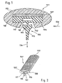
- Fig. 1 shows an inventive wiper blade 101 for a wiper device for wiping slices of Vehicles with a squeegee 102, which is one of the disc facing wiper lip 103, facing away from the disc Back part 104 and a wiper lip 103 with the back part 104 connecting tilting web 105 has.
- a cross section shown is a squeegee 102 stabilizing, band-like elastic carrying element 107 shown, which preferably with the Carrying member 107 facing side of the back portion 104th is glued.
- the support member 107 and the back part 104 of the squeegee 102 is of a sheath 108 completely enclosed.
- the sheath 108 is included streamlined and has a largely elliptical cross-section on. In parallel to the disk, directed to the longitudinal extent of the wiper blade 101 View corresponding to a view corresponding to the arrow 109 corresponds, is the tilting ridge 105 and one of the disc remote part 112 of the wiper lip 103 of the sheath 108 covered.
- the sheath 108 has on its the wiper lip 103rd side facing a surface structuring, namely spherical segment-shaped depressions 113, on, to the Reduction of air resistance of the wiper blade due to of the so-called golf ball effect are provided.
- a surface structuring namely spherical segment-shaped depressions 113, on
- the spherical segment-shaped Wells clearly visible.
- the wiper lip 103 is at the in Fig. 1 and Fig. 2 illustrated wiper blade 101 according to the invention with the Tilting web 105 extending in orthogonal to the disc Direction, which is indicated by the arrow 114, resilient stored.
- the back part 104 a membrane area, namely one in the back part itself in the longitudinal direction of the wiper blade 103 extending Cavity 117, on.
- the wall thickness 118 between the cavity 117 and the wiper lip 103 facing side of the Back portion 104 about the wall thickness of the tilting ridge 105th equivalent.
- the Carrying member 107 advantageously a metal spring element.
- the use of such a support member 107 has the Advantage that an increased torsional stiffness of Wiper blade can be achieved.
- the sheath 108 extends over the entire length of the wiper blade 101. Due to the in Fig. 1 clearly to recognizing wall thickness of the casing 108 has the Sheath 108 has a favorable intrinsic stability, which is the Wiper blade 101 stabilized in its entirety and especially a possible, by external influences caused plastic deformation of the support member 107th counteracts.
- the wiper blade 101 shown in Figs. 1 and 2 is very flat and has a very small Air resistance, especially through the elliptical Cross section of the largely of the casing 108 in Flow direction 109 of the wind covered wiper lip 103 as well as on the surface of the shell 108th arranged spherical segment-shaped recesses 113, on.
- This effect especially at higher Vehicle speeds lower incident forces on the Wiper blade 101 according to the invention Wiper blade 101 of the vehicle window is largely locked out.
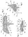
- the wiper blade generally designated 1 in FIG consists in a conventional manner of a wiper strip 2, which is made of a rubber-elastic material, and For example, by injection molding, pressing or Extrude, as well as two ribbon-like support and Spring rails 3 and 4, each of a resilient Flat strip material, for example made of spring steel or Spring band steel are made and the same as the Wiper strip 2 over the entire length of the wiper blade. 1 extend.
- the cross-sectional profile of the wiper strip 2 is made up an upper profile section or wiper strip body 5 as well from one over the bottom 6 of this wiper strip body wegmony wiper lip 7 together, which has a Kippsteg 8 is made in one piece with the wiper strip body 5 and in the case of use of the wiper blade 1 against the zu cleansing vehicle window is applied.
- M in Figure 3 denotes a median plane which the longitudinal axis of the wiper strip 2 includes and perpendicular lies to the drawing level of Figure 3.
- To this middle plane M are the wiper strip 2, the body 5, the wiper lip 7 and the tilting ridge 8 formed symmetrically.
- each groove 9 is a Spring rail 3 and 4 partially received, and indeed along an inner longitudinal edge 3 'and 4' of the respective spring rail 3 and 4.
- Each spring rail 3 and 4 stands out with the greater part of its width associated groove 9 laterally before.
- the spring rails 3 and 4 lie with their surface sides, i. with her upper and Bottom each in a common, perpendicular to Median plane M extending plane.
- the spring rails 3 and 4 respectively about two-thirds of its width from the respective groove 9 in front.
- the spring rails 3 and 4 At least at the two ends of the wiper blade 1 are the spring rails 3 and 4 in a conventional manner, e.g. connected by a connecting element and thereby also held on the wiper strip 2.
- the cross section of the cover 11 is of a strip-like section or body 12 formed on his the wiper lip 7 facing away from the top in substantially symmetric to the median plane M convex is, and about axes of curvature parallel to Longitudinal extension of the wiper blade 1.
- the body 12 with a Recess 13 provided in the illustrated Embodiment substantially symmetrical to the median plane M is formed and in which the two spring rails 3 and 4 with their out of the grooves 9 above areas as well also at least one upper section 5 'of the Wiper strip body 5 is added.
- Section 5 ' has the recess 13 in the middle of a extending over the entire length of the recess 13 Recess 13 ', whose cross section is the trapezoidal Cross-section of the top of the wiper strip 2 forming Section 5 'is adapted.
- the spring rails 3 and 4 engage with their outer longitudinal edges 3 '' and 4 '' in grooves 14 and 15, respectively, on the longitudinal sides of the Recess 13 are formed so that the cover 11 via the spring rails 3 is held on the wiper blade 1.
- the two Spring rails 3 and 4 are in turn only a part of their Width of the grooves 3 '' and 4 '' added, so that they in each case over a part of their width freely between the Grooves 9 and 14 and 15 extend.
- the body 12 goes in one over the Bottom of the cover 11 projecting strip-like and extending over the entire length of the cover 11 Section 16 on, with mounted cover 11 with its lower free edge 17 relative to a plane perpendicular to the median plane M at a common level 18 with the upper, the tilting ridge 8 facing the region of Wiper lip 7 is located.
- the wiper blade is 1 so mounted on the respective vehicle, that with the Section 16 provided longitudinal side of the wiper blade 1 in Driving direction of the vehicle front wiper blade longitudinal side forms.
- the section 16 forms a superior spoiler, and with an outer, the wiper strip.
- the cover 11 is made of a suitable, for example elastic material, e.g. made of a rubber elastic Made of plastic, e.g. by extruding a corresponding profile.
- a suitable, for example elastic material e.g. made of a rubber elastic Made of plastic, e.g. by extruding a corresponding profile.
- wiper blade 1 Another advantage of the wiper blade 1 is that by the shape of the cover 11, in particular by that of the section 16 formed superior spoiler, a especially low air resistance achieved and a Underflows of the wiper blade and a hereby connected Deterioration of wiping quality is prevented.
- FIG. 4 shows a further possible embodiment Wiper blade 1a, which from the wiper strip. 2 corresponding wiper strip 2a with the wiper strip body 5a and the wiper lip 7, formed over the tilting web 8, off the two spring rails 3 and 4 and from the cover 11a consists.
- the wiper blade 1a differs from the wiper blade 1 first in that the wiper strip body 5a at each Long side only has the groove 9 and the grooves 9 and the the grooves 14 and 15 on the sides of the recess 13th corresponding recess 13a chosen in depth so are that the spring rails 3 and 4 over its entire width each of a groove 9 and the adjacent groove 14 and 15 respectively are included.
- the recess 13a is so on the cross section of the wiper strip body 5a adapted that the latter completely fills the recess 13a or in the essentially completely absorbed by the recess 13a is.
- the cover 11a is at its Top flat and to the adjacent Longitudinal sides rounded off, the cover 11a on the when used in the direction of travel front long side of the Wiper blade 1a turn the over the bottom of the Cover projecting strip-like projection 16 with the free edge 17 forms.
- FIG. 5 shows a wiper blade as a further embodiment 1b, which is very similar to the wiper blade 1a and from the Wiper strip 2b with the wiper strip body 5b and the over the tilting web 8 molded wiper lip 7, from the two Spring rails 3 and 4 and the cover 11b exists.
- this embodiment is in cross section rectangular wiper strip body 5b completely in the on this cross-section adapted recess 13b of the cover 11b added.
- the cover 11b or its body 12b have a drop-shaped cross-sectional profile, i. one Cross-sectional profile on which the profile of a half Water drop is similar.
- the outer surface or outer contour the cover 11b is asymmetrical to the median plane M.
- the training continues to be such that the ratio H / B approximately in the range between 1/8 and 1/4 where B is the maximum width of the cover 11b in the axial direction perpendicular to the midplane M, and H the maximum height or the maximum distance between the level of the undersides of the spring rails 3 and 4 and the Top of the cover 11b is.
- the spring rails 3 and 4 lie with their surface sides turn in common Planes perpendicular to the median plane M.
- the cover 11b closes in FIG Area of the right in this figure long side, i. in the Area of the spring rail 4 flush with the bottom 6 b of Wiper strip 2b off, while on the opposite Long side, i. in the region of the spring rail 3, the cover 11b a projecting over the bottom 6b, over the entire length of the cover 11b extending portion 16b forms.
- This lies with its lower free edge again with respect to a plane perpendicular to the median plane M level with the upper area of the wiper lip 7 and complements the teardrop shape of the cover 11b at this Long side.
- the section is located 16b on the front in the direction of travel wiper blade longitudinal side.
- the wiper blade 1b has by the described shape of the Cover 1b the advantage of a particularly low Flow resistance, whereby wind noise is strong be reduced.
- the surface around it can also be filled with small extra Surveys, for example of the order of 0.1 - 2 be provided mm.
- FIG. 6 shows a further possible embodiment Wiper blade 1c, which differs from the wiper blade 1b in essential only differs in that instead of the Cover 11b with the drop shape contour a cover 11c is provided, the body 12c as a spoiler with a Spoiler constitution 20 is executed.
- the cover 11c As in the figure 6 with shown broken lines, there is the Possibility of the cover 11c on that long side, on the Spoiler composition 20 the smallest distance from the having cleaning vehicle window and based on the Direction of travel forms the front wiper blade longitudinal side, again with the downwardly projecting portion 16 Mistake.
- FIG. 7 shows in a simplified representation and in FIG Top view of a spring rail 21, which of a length a resilient sheet, namely for example one Spring band steel formed and suitably, provided for example by punching with a slot 22 is closed at the two ends of the spring rail 21 is.
- the slot 22 At one end of the spring rail, the slot 22 an extension to form an insertion opening 23.
- the width of the slot 22 corresponds to the distance that in the figures 3 - 6 the inside longitudinal edges 3 'and 4' of the spring rails 3 and 4 have.
- a width that is approximately equal to the width of each Wiper strip 2 - 2c is, so that the respective wiper strip by threading over the opening 23 on the spring rail 21st can be fixed so that the two sides of the slot 22 provided portions 21 'of the spring rail 21 in the Intervene grooves 9 and 14 and 15, as above for the spring rails 3 and 4 has been described.
- the spring rail 21 is for the wiper blades 1 - 1c instead of individual spring rails 3 and 4 used.
- the spring rail 21 but also in others Wiper blades can be used, consisting of a wiper strip and two engaging in lateral grooves of the wiper strip Spring rails exist.
- the invention relates to a wiper blade according to the preamble of claim 1 or 17, which is that according to DE 299 03 123 U1 generically formed.
- Wiper blades have become known from DE 299 03 123 U1.
- the one resilient insert with a tube-like have elastomeric enclosure, in which a squeegee is used.
- wiper blades to the Carrying element over the entire swept by the wiper blade Wiping field of the disc as evenly as possible distribution of the wiper blade outgoing wiper blade contact pressure at the Ensure disc.
- the support element points to it advantageously a suitable pre-bend on to a required, uniform wiper blade contact pressure against to reach the disc.
- the elaborate mounting bracket construction with two in the Wiper strip arranged spring rails replaced as they are conventional wiper blades is practiced and For example, from DE 15 053 97 A1 is known.
- the generic, known wiper blades have However, the disadvantage that they are a complex Have structure. Such a wiper blade looks next to the Carrying element arranged transversely to the support element Cross bars, arranged in the support element recesses and in the squeegee existing grooves for recording the surrounding the support member at least partially Sheath on. Such a construction of the wiper blade leads to a not insignificant height, which in the Driving brings great disadvantages. For example provides the side of the wiper blade facing the airstream a fairly large attack surface for the wiper blade impending wind. It also builds on the one of the Windward side facing away from the wiper blade considerable negative pressure.
- wiper blades consisting essentially of a wiper strip and at least one connected to this wiper strip Consist of spring rail.
- wiper blades have the disadvantage that the protruding spring rails to a high degree disturbing Noise, especially by the wind, generate and also pose a source of injury.
- a wiper blade is known in which the wiper is provided with two lateral grooves.
- These grooves are used spring rails, which in turn of a wraparound enclosing the wiper strip held become.
- the grooves do not form in this embodiment Tilting bridge around which the wiper lip can tilt. Therefore, the Cover also no Kippsteg cover.
- GB-A-2 346 318 also has the wiper strip no Kippsteg.
- the Wischleise molded grooves are spring rails and bent longitudinal edges of the wiper strip encompassing Cover inserted. A tilting of the wiper lip is not possible. Therefore, the grooves produce no Kippsteg.
- the object of the invention is to show a wiper blade, which while maintaining the basic advantages of a known wiper blade has improved properties.
- Such a wiper blade has in particular the advantage that it can be designed very flat and only a very low attack surface for the airstream forms.
- the carrying element, the back part as well as in particular also the tilting edge is covered by the sheathing, offers itself for the impact on the wiper blade, approximately to Disc parallel flow of the wind a very small Attack.
- Wiper blade has a very low overall weight and good can be mounted.
- the covers Sheath also facing away from the disc part of the Wiper lip off. This makes the wiper blade even flatter and a even more favorable flow behavior of the wiper blade be achieved.
- the sheathing a largely having elliptical cross-section.
- a elliptical cross section has a relatively small Flow resistance on.
- a elliptical cross section of the wiper strip according to the invention be made very flat.
- the sheath at least partially a surface structuring to reduce the Air resistance on. This will make it even better Wiping behavior of the wiper blade according to the invention achieved.
- the Sheath on the windward side of a turbulator is intended, also a create turbulent boundary layer, which positive Effects on the wiping behavior of the invention Wiper blade has.
- the Wiper strip with tilting bar in orthogonal to the pane extending direction resiliently arranged is the Wiper strip with tilting bar in orthogonal to the pane extending direction resiliently arranged.
- the Back part for the resilient arrangement of the wiper lip a Membrane area on.
- a membrane region arranged offers itself because the back part is immediate is arranged above the wiper lip and the Kippsteges.
- the wall thickness between the cavity and the wiper lip facing side of the Back part corresponds approximately to the wall thickness of the tilting ridge.
- This can be a particularly favorable springy elastic Tilting movement of the rubber lip can be achieved.
- the sheath has inherent stability, which stabilizes the wiper blade in its entirety and a plastic deformation of the support element counteracts.
- the casing thus takes over together with the carrying element, the Hältefunktion the wiper blade.
- the sheath also the free ends of the Carrying element and the back part. This can be the Intrinsic stability of the sheath can be additionally increased whereby the wiping behavior of the wiper strip also can be improved.
- a variant of the invention provides that the Back part facing side of the support member with the Carrier element facing side of the back part is glued. Due to such bonding, an improved Torsional stiffness of the wiper blade can be achieved.
- the Carrying element coated in particular plastic coated, is.
- the support element is particularly against environmental influences, such as e.g. Rainwater, protected.
- Fig. 1 shows an inventive wiper blade 101 for a wiper device for wiping slices of Vehicles with a squeegee 102, which is one of the disc facing wiper lip 103, facing away from the disc Back part 104 and a wiper lip 103 with the back part 104 connecting tilting web 105 has.
- a cross section shown is a squeegee 102 stabilizing, band-like elastic carrying element 107 shown, which preferably with the Carrying member 107 facing side of the back portion 104th is glued.
- the support member 107 and the back part 104 of the squeegee 102 is of a sheath 108 completely enclosed.
- the sheath 108 is included streamlined and has a largely elliptical cross-section on. In parallel to the disk, directed to the longitudinal extent of the wiper blade 101 View corresponding to a view corresponding to the arrow 109 corresponds, is the tilting ridge 105 and one of the disc remote part 112 of the wiper lip 103 of the sheath 108 covered.
- the sheath 108 has on its the wiper lip 103rd side facing a surface structuring, namely spherical segment-shaped depressions 113, on, to the Reduction of air resistance of the wiper blade due to of the so-called golf ball effect are provided.
- a surface structuring namely spherical segment-shaped depressions 113, on
- the spherical segment-shaped Wells clearly visible.
- the wiper lip 103 is at the in Fig. 1 and Fig. 2 illustrated wiper blade 101 according to the invention with the Tilting web 105 extending in orthogonal to the disc Direction, which is indicated by the arrow 114, resilient stored.
- the back part 104 a membrane area, namely one in the back part itself in the longitudinal direction of the wiper blade 103 extending Cavity 117, on.
- the wall thickness 118 between the cavity 117 and the wiper lip 103 facing side of the Back portion 104 about the wall thickness of the tilting ridge 105th equivalent.
- the Carrying member 107 advantageously a metal spring element.
- the use of such a support member 107 has the Advantage that an increased torsional stiffness of Wiper blade can be achieved.
- the sheath 108 extends over the entire length of the wiper blade 101. Due to the in Fig. 1 clearly to recognizing wall thickness of the casing 108 has the Sheath 108 has a favorable intrinsic stability, which is the Wiper blade 101 stabilized in its entirety and especially a possible, by external influences caused plastic deformation of the support member 107th counteracts.
- the wiper blade 101 shown in Figs. 1 and 2 is very flat and has a very small Air resistance, especially through the elliptical Cross section of the largely of the casing 108 in Flow direction 109 of the wind covered wiper lip 103 as well as on the surface of the shell 108th arranged spherical segment-shaped recesses 113, on.
- This effect especially at higher Vehicle speeds lower incident forces on the Wiper blade 101 according to the invention Wiper blade 101 of the vehicle window is largely locked out.
- the wiper blade generally designated 1 in FIG consists in a conventional manner of a wiper strip 2, which is made of a rubber-elastic material, and For example, by injection molding, pressing or Extrude, as well as two ribbon-like support and Spring rails 3 and 4, each of a resilient Flat strip material, for example made of spring steel or Spring band steel are made and the same as the Wiper strip 2 over the entire length of the wiper blade. 1 extend.
- the cross-sectional profile of the wiper strip 2 is made up an upper profile section or wiper strip body 5 as well from one over the bottom 6 of this wiper strip body wegmony wiper lip 7 together, which has a Kippsteg 8 is made in one piece with the wiper strip body 5 and in the case of use of the wiper blade 1 against the zu cleansing vehicle window is applied.
- M in Figure 3 denotes a median plane which the longitudinal axis of the wiper strip 2 includes and perpendicular lies to the drawing level of Figure 3.
- To this middle plane M are the wiper strip 2, the body 5, the wiper lip 7 and the tilting ridge 8 formed symmetrically.
- each groove 9 is a Spring rail 3 and 4 partially received, and indeed along an inner longitudinal edge 3 'and 4' of the respective spring rail 3 and 4.
- Each spring rail 3 and 4 stands out with the greater part of its width associated groove 9 laterally before.
- the spring rails 3 and 4 lie with their surface sides, i. with her upper and Bottom each in a common, perpendicular to Median plane M extending plane.
- the spring rails 3 and 4 respectively about two-thirds of its width from the respective groove 9 in front.
- the spring rails 3 and 4 At least at the two ends of the wiper blade 1 are the spring rails 3 and 4 in a conventional manner, e.g. connected by a connecting element and thereby also held on the wiper strip 2.
- the cross section of the cover 11 is of a strip-like section or body 12 formed on his the wiper lip 7 facing away from the top in substantially symmetric to the median plane M convex is, and about axes of curvature parallel to Longitudinal extension of the wiper blade 1.
- the body 12 with a Recess 13 provided in the illustrated Embodiment substantially symmetrical to the median plane M is formed and in which the two spring rails 3 and 4 with their out of the grooves 9 above areas as well also at least one upper section 5 'of the Wiper strip body 5 is added.
- Section 5 ' has the recess 13 in the middle of a extending over the entire length of the recess 13 Recess 13 ', whose cross section is the trapezoidal Cross-section of the top of the wiper strip 2 forming Section 5 'is adapted.
- the spring rails 3 and 4 engage with their outer longitudinal edges 3 '' and 4 '' in grooves 14 and 15, respectively, on the longitudinal sides of the Recess 13 are formed so that the cover 11 via the spring rails 3 is held on the wiper blade 1.
- the two Spring rails 3 and 4 are in turn only a part of their Width of the grooves 3 "and 4 '' added so that they in each case over a part of their width freely between the Grooves 9 and 14 and 15 extend.
- the body 12 goes in one over the Bottom of the cover 11 projecting strip-like and extending over the entire length of the cover 11 Section 16 on, with mounted cover 11 with its lower free edge 17 relative to a plane perpendicular to the median plane M at a common level 18 with the upper, the tilting ridge 8 facing the region of Wiper lip 7 is located.
- the wiper blade is 1 so mounted on the respective vehicle, that with the Section 16 provided longitudinal side of the wiper blade 1 in Driving direction of the vehicle front wiper blade longitudinal side forms.
- the section 16 forms a superior spoiler, and with an outer, the wiper strip.
- the cover 11 is made of a suitable, for example elastic material, e.g. made of a rubber elastic Made of plastic, e.g. by extruding a corresponding profile.
- a suitable, for example elastic material e.g. made of a rubber elastic Made of plastic, e.g. by extruding a corresponding profile.
- wiper blade 1 Another advantage of the wiper blade 1 is that by the shape of the cover 11, in particular by that of in the section 16 formed superior Spozler, a especially low air resistance achieved and a Underflows of the wiper blade and a hereby connected Deterioration of wiping quality is prevented.
- FIG. 4 shows a further possible embodiment Wiper blade 1a, which from the wiper strip. 2 corresponding wiper strip 2a with the wiper strip body 5a and the wiper lip 7, formed over the tilting web 8, off the two spring rails 3 and 4 and from the cover 11a consists.
- the wiper blade 1a differs from the wiper blade 1 first in that the wiper strip body 5a at each Long side only has the groove 9 and the grooves 9 and the the grooves 14 and 15 on the sides of the recess 13th corresponding recess 13a chosen in depth so are that the spring rails 3 and 4 over its entire width each of a groove 9 and the adjacent groove 14 and 15 respectively are included.
- the recess 13a is so on the cross section of the wiper strip body 5a adapted that the latter completely fills the recess 13a or in the essentially completely absorbed by the recess 13a is.
- the cover 11a is at its Top flat and to the adjacent Longitudinal sides rounded off, the cover 11a on the when used in the direction of travel front long side of the Wiper blade 1a turn the over the bottom of the Cover projecting strip-like projection 16 with the free edge 17 forms.
- FIG. 5 shows a wiper blade as a further embodiment 1b, which is very similar to the wiper blade 1a and from the Wiper strip 2b with the wiper strip body 5b and the over the tilting web 8 molded wiper lip 7, from the two Spring rails 3 and 4 and the cover 11b exists.
- this embodiment is in cross section rectangular wiper strip body 5b completely in the on this cross-section adapted recess 13b of the cover 11b added.
- the cover 11b or its body 12b have a drop-shaped cross-sectional profile, i. one Cross-sectional profile on which the profile of a half Water drop is similar.
- the outer surface or outer contour the cover 11b is asymmetrical to the median plane M.
- the training continues to be such that the ratio H / B approximately in the range between 1/8 and 1/4 where B is the maximum width of the cover 11b in the axial direction perpendicular to the midplane M, and H the maximum height or the maximum distance between the level of the undersides of the spring rails 3 and 4 and the Top of the cover 11b is.
- the spring rails 3 and 4 lie with their surface sides turn in common Planes perpendicular to the median plane M.
- the cover 11b closes in FIG Area of the right in this figure long side, i. in the Area of the spring rail 4 flush with the bottom 6 b of Wiper strip 2b off, while on the opposite Long side, i. in the region of the spring rail 3, the cover 11b a projecting over the bottom 6b, over the entire length of the cover 11b extending portion 16b forms.
- This lies with its lower free edge again with respect to a plane perpendicular to the median plane M level with the upper area of the wiper lip 7 and complements the teardrop shape of the cover 11b at this Long side.
- the section is located 16b on the front in the direction of travel wiper blade longitudinal side.
- the wiper blade 1b has by the described shape of the Cover 1b the advantage of a particularly low Flow resistance, whereby wind noise is strong be reduced.
- the surface around it can also be filled with small extra Surveys, for example of the order of 0.1 - 2 be provided mm.
- FIG. 6 shows a further possible embodiment Wiper blade 1c, which differs from the wiper blade 1b in essential only differs in that instead of the Cover 11b with the drop shape contour a cover 11c is provided, the body 12c as a spoiler with a Spoiler constitution 20 is executed.
- the cover 11c As in the figure 6 with shown broken lines, there is the Possibility of the cover 11c on that long side, on the Spoiler composition 20 the smallest distance from the having cleaning vehicle window and based on the Direction of travel forms the front wiper blade longitudinal side, again with the downwardly projecting portion 16 Mistake.
- FIG. 7 shows in a simplified representation and in FIG Top view of a spring rail 21, which of a length a resilient sheet, namely for example one Spring band steel formed and suitably, provided for example by punching with a slot 22 is closed at the two ends of the spring rail 21 is.
- the slot 22 At one end of the spring rail, the slot 22 an extension to form an insertion opening 23.
- the width of the slot 22 corresponds to the distance that in the figures 3 - 6 the inside longitudinal edges 3 'and 4' of the spring rails 3 and 4 have.
- a width that is approximately equal to the width of each Wiper strip 2 - 2c is, so that the respective wiper strip by threading over the opening 23 on the spring rail 21st can be fixed so that the two sides of the slot 22 provided portions 21 'of the spring rail 21 in the Intervene grooves 9 and 14 and 15, as above for the spring rails 3 and 4 has been described.
- the spring rail 21 is for the wiper blades 1 - 1c instead of individual spring rails 3 and 4 used.
- the spring rail 21 but also in others Wiper blades can be used, consisting of a wiper strip and two engaging in lateral grooves of the wiper strip Spring rails exist.
Landscapes
- Engineering & Computer Science (AREA)
- Mechanical Engineering (AREA)
- Physics & Mathematics (AREA)
- Fluid Mechanics (AREA)
- Quality & Reliability (AREA)
- Body Structure For Vehicles (AREA)
- Ink Jet (AREA)
- Cleaning Implements For Floors, Carpets, Furniture, Walls, And The Like (AREA)
- Springs (AREA)
- Seal Device For Vehicle (AREA)
Description
- Fig. 1:
- einen Querschnitt durch ein erstes Ausführungsbeispiel eines erfindungsgemäßen Wischblattes;
- Fig. 2:
- eine perspektivische Ansicht eines Ausschnitts des Wischblattes nach Fig. 1;
- Fig. 3 - 6
- jeweils in vereinfachter Darstellung und im Schnitt verschiedene mögliche Ausführungsformen des Wischblattes gemäß der Erfindung;
- Fig. 7
- in vereinfachter Darstellung und in Draufsicht eine Federschiene zur Verwendung bei einem der Wischblätter der Figuren 3 - 6.
- Durch die Abdeckung 11 wird eine Verletzungsgefahr an den seitlich über die Wischleiste 2 wegstehenden Federschienen 3 und 4 vermieden;
- durch die Abdeckung 11 wird für das Wischblatt eine strömungstechnisch optimale äußere Kontur erreicht, so daß bei guter Wischqualität des Wischblattes auch störende, bei hohen Fahrgeschwindigkeiten durch den Luftstrom erzeugte Geräusche vermieden sind.;
- durch die Verwendung der Abdeckung 11 ist es weiterhin möglich, die Federschienen 3 und 4 mit einer im Vergleich zur Wischleiste 2 großen Breite auszubilden oder umgekehrt, die Wischleiste 2 sehr schmal und kompakt zu halten, wobei der Querschnitt der Federschienen 3 und 4 in jedem Fall so gewählt werden kann, daß ein optimales Anliegen des Wischblattes 1 gegen die Fahrzeugscheibe und damit eine optimale Wischqualität gewährleistet sind.
- 1, 1a, 1b, 1c
- Wischblatt
- 2, 2a, 2b, 2c
- Wischleiste
- 3, 4
- Federschiene
- 3', 4'; 3'', 4''
- Federschienenlängsseite
- 5, 5a, 5b, 5c
- Wischleistenkörper
- 5'
- Abschnitt
- 6, 6b
- Wischleistenunterseite
- 7
- Wischlippe
- 8
- Kippsteg
- 9, 10
- Nut
- 11, 11a, 11b, 11c
- Abdeckung
- 12, 12a, 12b, 12c
- Abdeckungskörper
- 13, 13a, 13b, 13c
- Ausnehmung
- 13'
- Vertiefung
- 14, 15
- Nut
- 16, 16b
- leistenartiger Vorsprung
- 16'
- Spoilerfläche
- 17
- Rand
- 18
- Niveau
- 19
- Rand
- 20
- Spoilerfläche
- 21
- Federschiene
- 21'
- Abschnitt
- 22
- Schlitz
- 23
- Einführöffnung
- 101
- Wischblatt
- 102
- Wischgummi
- 103
- Wischlippe
- 104
- Rückenteil
- 105
- Kippsteg
- 107
- Trageelement
- 108
- Ummantelung
- 109
- Ansicht
- 112
- Teil Wischlippe
- 113
- kugelsegmentförmige Vertiefungen
- 114
- Richtung Federung (103)
- 117
- Hohlraum
- 118
- Wandstärke
- Fig. 1:
- einen Querschnitt durch ein erstes Ausführungsbeispiel eines erfindungsgemäßen Wischblattes;
- Fig. 2:
- eine perspektivische Ansicht eines Ausschnitts des Wischblattes nach Fig. 1;
- Fig. 3 - 6
- jeweils in vereinfachter Darstellung und im Schnitt verschiedene mögliche Ausführungsformen des Wischblattes gemäß der Erfindung;
- Fig. 7
- in vereinfachter Darstellung und in Draufsicht eine Federschiene zur Verwendung bei einem der Wischblätter der Figuren 3 - 6.
- Durch die Abdeckung 11 wird eine Verletzungsgefahr an den seitlich über die Wischleiste 2 wegstehenden Federschienen 3 und 4 vermieden;
- durch die Abdeckung 11 wird für das Wischblatt eine strömungstechnisch optimale äußere Kontur erreicht, so daß bei guter Wischqualität des Wischblattes auch störende, bei hohen Fahrgeschwindigkeiten durch den Luftstrom erzeugte Geräusche vermieden sind.;
- durch die Verwendung der Abdeckung 11 ist es weiterhin möglich, die Federschienen 3 und 4 mit einer im Vergleich zur Wischleiste 2 großen Breite auszubilden oder umgekehrt, die Wischleiste 2 sehr schmal und kompakt zu halten, wobei der Querschnitt der Federschienen 3 und 4 in jedem Fall so gewählt werden kann, daß ein optimales Anliegen des Wischblattes 1 gegen die Fahrzeugscheibe und damit eine optimale Wischqualität gewährleistet sind.
- 1, 1a, 1b, 1c
- Wischblatt
- 2, 2a, 2b, 2c
- Wischleiste
- 3, 4
- Federschiene
- 3', 4'; 3'', 4''
- Federschienenlängsseite
- 5, 5a, 5b, 5c
- Wischleistenkörper
- 5'
- Abschnitt
- 6, 6b
- Wischleistenunterseite
- 7
- Wischlippe
- 8
- Kippsteg
- 9, 10
- Nut
- 11, 11a, 11b, 11c
- Abdeckung
- 12, 12a, 12b, 12c
- Abdeckungskörper
- 13, 13a, 13b, 13c
- Ausnehmung
- 13'
- Vertiefung
- 14, 15
- Nut
- 16, 16b
- leistenartiger Vorsprung
- 16'
- Spoilerfläche
- 17
- Rand
- 18
- Niveau
- 19
- Rand
- 20
- Spoilerfläche
- 21
- Federschiene
- 21'
- Abschnitt
- 22
- Schlitz
- 23
- Einführöffnung
- 101
- Wischblatt
- 102
- Wischgummi
- 103
- Wischlippe
- 104
- Rückenteil
- 105
- Kippsteg
- 107
- Trageelement
- 108
- Ummantelung
- 109
- Ansicht
- 112
- Teil Wischlippe
- 113
- kugelsegmentförmige Vertiefungen
- 114
- Richtung Federung (103)
- 117
- Hohlraum
- 118
- Wandstärke
Claims (31)
- Wischblatt (101) für eine Wischeinrichtung zum Wischen von Scheiben von Fahrzeugen mit einem Wischgummi (102), das eine der Scheibe zugewandte Wischlippe (103), ein der Scheibe abgewandtes Rückenteil (104) und einen die Wischlippe (103) mit dem Rückenteil (104) verbindenden Kippsteg (105) aufweist, mit einem das Wischgummi (102) stabilisierenden, bandartigen, federelastischen Trageelement (107), welches mit einem quer zu der Längserstreckung des Wischblattes antreibbaren, zur Scheibe belastbaren Wischarm verbindbar ist und mit einer das Rückenteil (104) und das Trageelement (107) wenigstens abschnittsweise umgebenden Ummantelung (108), welche strömungsgünstig ausgebildet ist, in Längserstreckung des Wischblattes (101) das Trageelement (107) und das Rückenteil (104) umschließt und die der Wischlippe (103) abgewandte Oberseite des Rückenteiles (104) abdeckt und weiterhin in zu der Scheibe paralleler, auf die Längserstreckung des Wischblattes (101) gerichteter Ansicht, die der Strömungsrichtung (109) entspricht, den Kippsteg (105) abdeckt.
- Wischblatt (101) nach Anspruch 1, wobei die Ummantelung (108) auch den der Scheibe abgewandten Teil (112) der Wischlippe (103) abdeckt.
- Wischblatt (101) nach Anspruch 1 und 2, wobei die Ummantelung (108) einen weitgehend elliptischen Querschnitt aufweist.
- Wischblatt (101) nach einem der vorhergehenden Ansprüche, wobei die Ummantelung (108) wenigstens abschnittsweise eine Oberflächenstrukturierung zur Reduzierung des Luftwiderstandes aufweist.
- Wischblatt (101) nach Anspruch 4, wobei die Oberflächenstrukturierung kugelsegmentförmige Vertiefungen (113) aufweist.
- Wischblatt (101) nach einem der vorhergehenden Ansprüche, wobei die Ummantelung (108) an der Luvseite einen Turbulator aufweist.
- Wischblatt (101) nach einem der vorhergehenden Ansprüche, wobei die Wischlippe (103) mit Kippsteg (105) in orthogonal zur Scheibe verlaufender Richtung federnd angeordnet ist.
- Wischblatt (101) nach Anspruch 7, wobei zur federnden Anordnung der Wischlippe (103) das Rückenteil (104) einen Membranbereich aufweist.
- Wischblatt (101) nach Anspruch 8, wobei der Membranbereich durch wenigstens einen in dem Rückenteil (104) vorhandenen Hohlraum (117) gebildet wird.
- Wischblatt (101) nach Anspruch 9, wobei die Wandstärke (18) zwischen dem Hohlraum (117) und der der Wischlippe (103) zugewandten Seite des Rückenteils (104) etwa der Wandstärke des Kippsteges (105) entspricht.
- Wischblatt (101) nach einem der vorhergehenden Ansprüche, wobei die Ummantelung (108) eine Eigenstabilität aufweist, die das Wischblatt (1) in seiner Gesamtheit stabilisiert und einer plastischen Verformung des Trageelements (107) entgegenwirkt.
- Wischblatt (101) nach einem der vorhergehenden Ansprüche, wobei die Ummantelung (108) auch die freien Enden des Trageelements (107) und des Rückenteils (104) umschließt.
- Wischblatt (101) nach den Ansprüchen 1-11, wobei die Ummantelung (108) an ihren freien Enden Abdeckkappen aufweist.
- Wischblatt (101) nach einem der vorhergehenden Ansprüche, wobei die dem Rückenteil (104) zugewandte Seite des Trageelements (107) mit der dem Trageelement (107) zugewandten Seite des Rückenteils (104) verklebt ist.
- Wischblatt (101) nach einem der vorhergehenden Ansprüche, wobei das Trageelement (104) ein Metallfederelement und dass die Ummantelung (108) ein Kunststoffelement ist.
- Wischblatt (101) nach einem der vorhergehenden Ansprüche, wobei das Trageelement (104) beschichtet, insbesondere kunststoffbeschichtet, ist.
- Wischblatt (1) zum Reinigen von Scheiben an Fahrzeugen, insbesondere Kraftfahrzeugen, mit einer aus einem gummielastischen Material hergestellten langgestreckten Wischleiste (2), die im Bereich ihrer Unterseite einstückig mit wenigstens einer an der jeweiligen Fahrzeugscheibe anlegbaren Wischlippe (7) hergestellt ist, sowie mit wenigstens einer sich in Längsrichtung der Wischleiste (2, 2a, 2b, 2c) erstreckenden und an dieser gehaltenen Federschiene (3, 4, 21), die mit wenigstens einer außen liegenden Längskante (3'', 4'') über eine Längsseite der Wischleiste vorsteht, wobei an der wenigstens einen Federschiene (3, 4) eine die Wischleiste (2, 2a, 2b, 2c) an ihrer der Wischlippe (7) abgewandten Oberseite abdeckende Abdeckung (11, 11a, 11b, 11c) gehalten ist, welche strömungsgünstig ausgebildet ist und in zu der Scheibe paralleler, auf die Längserstreckung des Wischblattes (1) gerichteter Ansicht, die der Strömungsrichtung (109) entspricht, einen die Wischlippe (7) mit einem Wischleistenkörper (5) verbindenden Kippsteg (8) abdeckt.
- Wischblatt nach Anspruch 17, wobei die Abdeckung (11, 11a, 11b, 11c) auch die wenigstens eine Federschiene abdeckt.
- Wischblatt nach einem der vorhergehenden Ansprüche, wobei die Abdeckung (11, 11a, 11b, 11c) durch Einrasten an der wenigstens einen Federschiene (3,4 ; 21) gehalten ist.
- Wischblatt nach einem der vorhergehenden Ansprüche, wobei die Abdeckung (11, 11a, 11b, 11c) Ausnehmungen (14,15) aufweist, in die die wenigstens eine Federschiene (3,4 ; 21) mit ihren außen liegenden Längskanten (3'', 4'') eingreift.
- Wischblatt nach einem der vorhergehenden Ansprüche, wobei die Abdeckung an ihrer der Unterseite der Wischleiste (2,2a, 2b, 2c) zugewandten Unterseite mit einer Ausnehmung (13,13a, 13b, 13c) versehen ist, in der die Wischleiste (2,2a, 2b, 2c) zumindest teilweise aufgenommen ist.
- Wischblatt nach einem der vorhergehenden Ansprüche, wobei zwei getrennte Federschienen (3,4) vorgesehen sind, von denen jede in eine längsseitige Nut (9) der Wischleiste (2,2a, 2b, 2c) eingreift und aus dieser Nut über die betreffende Seite der Wischleiste vorsteht.
- Wischblatt nach einem der vorhergehenden Ansprüche 17 21, wobei eine einzige Federschiene (21) vorgesehen ist, die mit zwei Längskanten jeweils über eine Längsseite der Wischleiste (2,2a, 2b, 2c) vorsteht, und dass die Abdeckung (11, 11a, 11b, 11c) an beiden Längskanten der Federschiene (21) gehalten ist.
- Wischblatt nach Anspruch 23, wobei die Federschiene (21) beidseitig von wenigstens einem Schlitz (22) Federschienenabschnitte (21') bildet.
- Wischblatt nach Anspruch 24, wobei die Federschienenabschnitte (21') jeweils in einer längsseitigen Nut (9) der Wischleiste (2,2a, 2b, 2c) aufgenommen sind, und dass der Schlitz (22) der Federschiene (21) vom Material der Wischleiste (2,2a, 2b, 2c) zumindest teilweise eingenommen ist.
- Wischblatt nach einem der vorhergehenden Ansprüche, wobei die Abdeckung (11) haubenartig, vorzugsweise mit einer konvex gekrümmten Oberseite ausgebildet ist.
- Wischblatt nach einem der vorhergehenden Ansprüche, wobei die Abdeckung (11b) im Querschnitt eine einer Tropfenform oder einem Teil einer Tropfenform entsprechende Außenkontur aufweist.
- Wischblatt nach einem der vorhergehenden Ansprüche 17 - 26, wobei die Abdeckung (11c) an ihrer Oberseite als Spoiler mit wenigstens einer Spoilerfläche (20) ausgebildet ist.
- Wischblatt nach einem der vorhergehenden Ansprüche, wobei die Abdeckung (11, 11b, 11c) an wenigstens einer Längsseite des Wischblattes (1, 1b, 1c) einen über die Unterseite der Abdeckung wegstehenden leistenartigen Abschnitt (16,16a, 16b) aufweist.
- Wischblatt nach Anspruch 29, wobei der leistenartige Abschnitt (16) an einer der Wischleiste abgewandten Außenfläche als Spoiler ausgebildet bzw. mit einer Spoilerfläche (16') versehen ist.
- Wischblatt nach einem der vorhergehenden Ansprüche, wobei die Abdeckung (11, 11a, 11b, 11c) aus einem elastischen Material, beispielsweise aus elastischen Kunststoff hergestellt ist.
Applications Claiming Priority (5)
| Application Number | Priority Date | Filing Date | Title |
|---|---|---|---|
| DE10007800 | 2000-02-21 | ||
| DE2000107809 DE10007809A1 (de) | 2000-02-21 | 2000-02-21 | Wischblatt für eine Wischeinrichtung |
| DE2000107800 DE10007800A1 (de) | 2000-02-21 | 2000-02-21 | Wischblatt |
| DE10007809 | 2000-02-21 | ||
| PCT/EP2001/001888 WO2001062561A1 (de) | 2000-02-21 | 2001-02-20 | Wischblatt zum reinigen von scheiben von kraftfahrzeugen |
Publications (2)
| Publication Number | Publication Date |
|---|---|
| EP1257445A1 EP1257445A1 (de) | 2002-11-20 |
| EP1257445B1 true EP1257445B1 (de) | 2005-04-13 |
Family
ID=26004441
Family Applications (1)
| Application Number | Title | Priority Date | Filing Date |
|---|---|---|---|
| EP01905804A Expired - Lifetime EP1257445B1 (de) | 2000-02-21 | 2001-02-20 | Wischblatt zum reinigen von scheiben von kraftfahrzeugen |
Country Status (8)
| Country | Link |
|---|---|
| US (1) | US7523519B2 (de) |
| EP (1) | EP1257445B1 (de) |
| JP (1) | JP2003530257A (de) |
| CN (1) | CN100417556C (de) |
| BR (1) | BR0108531A (de) |
| DE (1) | DE50105902D1 (de) |
| ES (1) | ES2241786T3 (de) |
| WO (1) | WO2001062561A1 (de) |
Cited By (10)
| Publication number | Priority date | Publication date | Assignee | Title |
|---|---|---|---|---|
| WO2007137891A1 (de) * | 2006-05-26 | 2007-12-06 | Robert Bosch Gmbh | Wischblatt mit mindestens einem tragelement und einem spoiler |
| DE102009037683A1 (de) * | 2009-07-13 | 2011-01-27 | You, Haiyong, Ningbo | Bügelloser Universalscheibenwischer |
| US8806700B2 (en) | 2011-07-29 | 2014-08-19 | Pylon Manufacturing Corporation | Wiper blade connector |
| US8935825B2 (en) | 2012-06-25 | 2015-01-20 | Cap Corporation | Wiper blade assembly |
| US9108595B2 (en) | 2011-07-29 | 2015-08-18 | Pylon Manufacturing Corporation | Windshield wiper connector |
| US9108594B2 (en) | 2009-08-26 | 2015-08-18 | Cap Corporation | Multi-adapter for a vehicle wiper |
| US9457768B2 (en) | 2011-04-21 | 2016-10-04 | Pylon Manufacturing Corp. | Vortex damping wiper blade |
| US9505380B2 (en) | 2014-03-07 | 2016-11-29 | Pylon Manufacturing Corp. | Windshield wiper connector and assembly |
| USD777079S1 (en) | 2014-10-03 | 2017-01-24 | Pylon Manufacturing Corp. | Wiper blade frame |
| WO2026013297A1 (fr) * | 2024-07-11 | 2026-01-15 | Valeo Systèmes d'Essuyage | Elément et dispositif d'essuyage de véhicule automobile |
Families Citing this family (41)
| Publication number | Priority date | Publication date | Assignee | Title |
|---|---|---|---|---|
| ATE299818T1 (de) * | 2000-05-29 | 2005-08-15 | Bosch Gmbh Robert | Wischblatt zum reinigen von scheiben insbesondere von kraftfahrzeugen |
| DE10120467A1 (de) * | 2001-04-26 | 2002-10-31 | Bosch Gmbh Robert | Wischblatt zum Reinigen von Scheiben, insbesondere von Kraftfahrzeugen |
| DE10207706A1 (de) * | 2002-02-22 | 2003-09-04 | Bosch Gmbh Robert | Wischblatt zum Reinigen von Scheiben insbesondere von Kraftfahrzeugen |
| JP3898186B2 (ja) * | 2003-02-14 | 2007-03-28 | ケーシーダブリュー コーポレーション | 車両用ワイパーブレード組立体 |
| FR2868747B1 (fr) | 2004-04-07 | 2008-06-20 | Valeo Systemes Dessuyage | Balai d'essuie-glace de type flat-blade comportant un deflecteur aerodynamique |
| CA2514372A1 (en) * | 2004-07-30 | 2006-01-30 | M Management-Tex, Ltd. | Windshield wiper structure |
| US20060026786A1 (en) * | 2004-08-04 | 2006-02-09 | Shu-Lan Ku | Windshield wiper |
| BRMU8402004U (pt) † | 2004-08-17 | 2004-12-28 | Dyna Electromecanica | Disposição introduzida em palheta |
| US20070022556A1 (en) * | 2005-07-28 | 2007-02-01 | Walworth Van T | Wind deflector with symmetrical geometry |
| USD597017S1 (en) | 2006-01-27 | 2009-07-28 | Fukoku Co., Ltd. | Wiper blade rubber |
| JP4924085B2 (ja) * | 2007-02-21 | 2012-04-25 | 市光工業株式会社 | ワイパーブレードの防水カバー及びその製造方法 |
| USD633426S1 (en) | 2007-11-27 | 2011-03-01 | Fukoku Co., Ltd. | Wiper blade rubber |
| EP2106978B1 (de) * | 2008-03-31 | 2017-03-08 | Federal-Mogul S.A. | Scheibenwischervorrichtung mit einem elastischen, länglichen Trägerelement, sowie längliches Wischblatt aus einem flexiblen Material, das in einer Stütze mit der Scheibe, die gewischt werden soll, angebracht werden kann |
| DE102008041077A1 (de) * | 2008-08-07 | 2010-02-11 | Robert Bosch Gmbh | Wischleiste |
| EP2319739A2 (de) * | 2008-08-25 | 2011-05-11 | Cap Corporation | Flacher fahrzeugscheibenwischer mit hydraulischer stossdämpfungseinheit |
| CA2753533C (en) * | 2009-02-27 | 2016-12-20 | Trico Products Corporation | Windshield wiper assembly having an optimized airfoil |
| US8495787B2 (en) | 2010-08-03 | 2013-07-30 | Rally Manufacturing, Inc. | Windshield wiper |
| USD706200S1 (en) | 2010-09-22 | 2014-06-03 | Pylon Manufacturing Corporation | Windshield wiper cover |
| DE102010062632A1 (de) * | 2010-12-08 | 2012-06-14 | Robert Bosch Gmbh | Wischarm und Wischblatt für eine Scheibenwischvorrichtung eines Kraftfahrzeugs |
| JP5666684B2 (ja) * | 2011-02-23 | 2015-02-12 | 株式会社ミツバ | ワイパブレード |
| US9174609B2 (en) | 2011-04-21 | 2015-11-03 | Pylon Manufacturing Corp. | Wiper blade with cover |
| MX345011B (es) | 2011-07-28 | 2017-01-11 | Pylon Mfg Corp | Adaptador, conector y conjunto de limpiaparabrisas. |
| WO2013019645A1 (en) | 2011-07-29 | 2013-02-07 | Pylon Manufacturing Corp. | Windshield wiper connector |
| US20130219649A1 (en) | 2012-02-24 | 2013-08-29 | Pylon Manufacturing Corp. | Wiper blade |
| RU2577981C1 (ru) | 2012-02-24 | 2016-03-20 | Пилон Мануфэкчуринг Корп. | Щетка стеклоочистителя |
| US10723322B2 (en) | 2012-02-24 | 2020-07-28 | Pylon Manufacturing Corp. | Wiper blade with cover |
| DE102012210203A1 (de) * | 2012-06-18 | 2013-12-19 | Robert Bosch Gmbh | Wischblattvorrichtung |
| US10829092B2 (en) | 2012-09-24 | 2020-11-10 | Pylon Manufacturing Corp. | Wiper blade with modular mounting base |
| US10166951B2 (en) | 2013-03-15 | 2019-01-01 | Pylon Manufacturing Corp. | Windshield wiper connector |
| KR101474838B1 (ko) | 2013-07-01 | 2014-12-22 | 주식회사 캐프 | 와이퍼 블레이드 조립체 |
| FR3023775B1 (fr) * | 2014-07-17 | 2016-08-05 | Valeo Systemes Dessuyage | Balai plat carene d'essuie-glace |
| USD787308S1 (en) | 2014-10-03 | 2017-05-23 | Pylon Manufacturing Corp. | Wiper blade package |
| USD785539S1 (en) * | 2015-08-31 | 2017-05-02 | Edwin PHILLIP | Aftermarket side window wiper design for a motor vehicle |
| EP3368383B1 (de) | 2015-10-26 | 2021-08-04 | Pylon Manufacturing Corp. | Wischerblatt |
| KR101795447B1 (ko) * | 2015-12-28 | 2017-11-09 | 고수연 | 부상방지기능이 향상된 스포일러와 이를 포함하는 자동차용 와이퍼장치 |
| US10717414B2 (en) | 2016-05-19 | 2020-07-21 | Pylon Manufacturing Corporation | Windshield wiper blade |
| CN109715449A (zh) | 2016-05-19 | 2019-05-03 | 电缆塔制造有限公司 | 挡风玻璃雨刮器连接器 |
| AU2017268019A1 (en) | 2016-05-19 | 2018-11-22 | Pylon Manufacturing Corp. | Windshield wiper connector |
| US11040705B2 (en) | 2016-05-19 | 2021-06-22 | Pylon Manufacturing Corp. | Windshield wiper connector |
| CN109311452A (zh) | 2016-05-19 | 2019-02-05 | 电缆塔制造有限公司 | 挡风玻璃雨刮器连接器 |
| CN112826359B (zh) * | 2019-11-25 | 2024-05-28 | 苏州市春菊电器有限公司 | 一种具有新型集水条的擦窗机刷头 |
Family Cites Families (17)
| Publication number | Priority date | Publication date | Assignee | Title |
|---|---|---|---|---|
| US3088155A (en) * | 1960-02-23 | 1963-05-07 | Trico Products Corp | Windscreen wipers |
| US3114926A (en) * | 1961-09-25 | 1963-12-24 | Trico Products Corp | Windshield wiper |
| DE1505397A1 (de) * | 1965-05-07 | 1969-10-30 | Bosch Gmbh Robert | Scheibenwischer fuer Fahrzeuge |
| US3317945A (en) * | 1965-09-17 | 1967-05-09 | Hastings Mfg Co | Molded windshield wiper blade |
| GB1438568A (en) * | 1972-09-09 | 1976-06-09 | Fister Snc Di Bosso Giacomo C | Windshield wiper blade |
| JPS5755649U (de) * | 1980-09-19 | 1982-04-01 | ||
| DE3139445A1 (de) * | 1981-10-03 | 1983-04-21 | SWF-Spezialfabrik für Autozubehör Gustav Rau GmbH, 7120 Bietigheim-Bissingen | Wischblatt fuer scheibenreinigungsanlagen an fahrzeugen, insbesondere an kraftfahrzeugen |
| JPS6115662U (ja) * | 1984-07-03 | 1986-01-29 | 日本ワイパブレ−ド株式会社 | ブレ−ドラバ− |
| JPH0633948Y2 (ja) * | 1989-03-30 | 1994-09-07 | 株式会社アシックス | 跳び縄運動具 |
| FR2679185A1 (fr) * | 1991-07-16 | 1993-01-22 | Journee Paul Sa | Deflecteur aerodynamique pour balai d'essuie-glace equipe d'une garniture souple. |
| JPH0525902U (ja) * | 1991-09-09 | 1993-04-02 | 財団法人鉄道総合技術研究所 | 低空力音型集電装置 |
| DE19736368B4 (de) * | 1997-08-21 | 2007-10-04 | Robert Bosch Gmbh | Wischblatt für Scheiben von Kraftfahrzeugen |
| DE19801058A1 (de) * | 1998-01-14 | 1999-07-15 | Bosch Gmbh Robert | Wischblatt zum Reinigen von Scheiben von Kraftfahrzeugen |
| DE19856300A1 (de) | 1998-12-07 | 2000-06-08 | Bosch Gmbh Robert | Wischblatt für Scheiben von Kraftfahrzeugen |
| GB2346318A (en) | 1999-02-02 | 2000-08-09 | Rover Group | Extruded plastics wiper blade carrier |
| DE29903123U1 (de) * | 1999-02-20 | 1999-07-15 | Bähr, Marcus, 89186 Illerrieden | Scheibenwischer für Fahrzeuge aller Art |
| US6266843B1 (en) * | 1999-05-03 | 2001-07-31 | Ford Global Technologies,Inc. | Vehicle window wiper assembly having one-piece carrier with flexible tips |
-
2001
- 2001-02-20 WO PCT/EP2001/001888 patent/WO2001062561A1/de not_active Ceased
- 2001-02-20 EP EP01905804A patent/EP1257445B1/de not_active Expired - Lifetime
- 2001-02-20 CN CNB018052886A patent/CN100417556C/zh not_active Expired - Fee Related
- 2001-02-20 US US10/203,997 patent/US7523519B2/en not_active Expired - Fee Related
- 2001-02-20 BR BR0108531-0A patent/BR0108531A/pt not_active Application Discontinuation
- 2001-02-20 ES ES01905804T patent/ES2241786T3/es not_active Expired - Lifetime
- 2001-02-20 JP JP2001561588A patent/JP2003530257A/ja active Pending
- 2001-02-20 DE DE50105902T patent/DE50105902D1/de not_active Expired - Fee Related
Cited By (11)
| Publication number | Priority date | Publication date | Assignee | Title |
|---|---|---|---|---|
| WO2007137891A1 (de) * | 2006-05-26 | 2007-12-06 | Robert Bosch Gmbh | Wischblatt mit mindestens einem tragelement und einem spoiler |
| DE102009037683A1 (de) * | 2009-07-13 | 2011-01-27 | You, Haiyong, Ningbo | Bügelloser Universalscheibenwischer |
| US9108594B2 (en) | 2009-08-26 | 2015-08-18 | Cap Corporation | Multi-adapter for a vehicle wiper |
| US9457768B2 (en) | 2011-04-21 | 2016-10-04 | Pylon Manufacturing Corp. | Vortex damping wiper blade |
| US8806700B2 (en) | 2011-07-29 | 2014-08-19 | Pylon Manufacturing Corporation | Wiper blade connector |
| US9108595B2 (en) | 2011-07-29 | 2015-08-18 | Pylon Manufacturing Corporation | Windshield wiper connector |
| US8935825B2 (en) | 2012-06-25 | 2015-01-20 | Cap Corporation | Wiper blade assembly |
| US9505380B2 (en) | 2014-03-07 | 2016-11-29 | Pylon Manufacturing Corp. | Windshield wiper connector and assembly |
| USD777079S1 (en) | 2014-10-03 | 2017-01-24 | Pylon Manufacturing Corp. | Wiper blade frame |
| WO2026013297A1 (fr) * | 2024-07-11 | 2026-01-15 | Valeo Systèmes d'Essuyage | Elément et dispositif d'essuyage de véhicule automobile |
| FR3164429A1 (fr) * | 2024-07-11 | 2026-01-16 | Valeo Systèmes D’Essuyage | Elément et dispositif d’essuyage de véhicule automobile |
Also Published As
| Publication number | Publication date |
|---|---|
| CN100417556C (zh) | 2008-09-10 |
| ES2241786T3 (es) | 2005-11-01 |
| US20030014828A1 (en) | 2003-01-23 |
| EP1257445A1 (de) | 2002-11-20 |
| US7523519B2 (en) | 2009-04-28 |
| CN1606514A (zh) | 2005-04-13 |
| BR0108531A (pt) | 2003-04-22 |
| JP2003530257A (ja) | 2003-10-14 |
| DE50105902D1 (de) | 2005-05-19 |
| WO2001062561A1 (de) | 2001-08-30 |
Similar Documents
| Publication | Publication Date | Title |
|---|---|---|
| EP1257445A1 (de) | Wischblatt zum reinigen von scheiben von kraftfahrzeugen | |
| EP1244581B1 (de) | Wischvorrichtung zum reinigen von scheiben an fahrzeugen, insbesondere kraftfahrzeugen | |
| EP1178907B1 (de) | Wischblatt zum reinigen von scheiben an fahrzeugen, insbesondere kraftfahrzeugen | |
| EP0929423B1 (de) | Wischblatt für scheiben von kraftfahrzeugen | |
| DE3139445C2 (de) | ||
| DE102004064199B3 (de) | Wischerblatt mit einem mit dem Wischerarm verbundenen Hebel | |
| EP0930990B1 (de) | Wischblatt für scheiben von kraftfahrzeugen | |
| EP1289804B1 (de) | Wischblatt zum reinigen von fahrzeugscheiben | |
| EP1289805B1 (de) | Wischblatt zum reinigen von fahrzeugscheiben | |
| EP1802497B1 (de) | Wischblatt | |
| DE112006001980T5 (de) | Windabweiser mit symmetrischer Geometrie | |
| DE10120467A1 (de) | Wischblatt zum Reinigen von Scheiben, insbesondere von Kraftfahrzeugen | |
| DE102011053350B4 (de) | Luftströmungs-Ablenkeinrichtung für Fahrzeuge | |
| DE10044913B4 (de) | Wischblatt zum Reinigen von Scheiben, insbesondere von Kraftfahrzeugen | |
| DE102008041077A1 (de) | Wischleiste | |
| EP3717311B1 (de) | Wischleiste für ein wischblatt | |
| DE4311342C2 (de) | Karosserie für Personenkraftwagen | |
| WO2003013918A1 (de) | Wischblatt, insbesondere flachwischblatt | |
| DE2838451C3 (de) | Vorrichtung zum Verhindern des Abhebens von Scheibenwischerblättern infolge Fahrtwind bei Kraftfahrzeugen | |
| EP0958162B1 (de) | Wischblatt | |
| DE10340140B4 (de) | Gelenkfreies Wischblatt | |
| DE69104506T2 (de) | Scheibenwischerleiste und Scheibenwischerblatt ausgestattet mit solch einer Leiste. | |
| DE10007800A1 (de) | Wischblatt | |
| DE10014803A1 (de) | Wischerblatt | |
| WO2016096453A1 (de) | Scheibenwischvorrichtung |
Legal Events
| Date | Code | Title | Description |
|---|---|---|---|
| PUAI | Public reference made under article 153(3) epc to a published international application that has entered the european phase |
Free format text: ORIGINAL CODE: 0009012 |
|
| 17P | Request for examination filed |
Effective date: 20020723 |
|
| AK | Designated contracting states |
Kind code of ref document: A1 Designated state(s): AT BE CH CY DE DK ES FI FR GB GR IE IT LI LU MC NL PT SE TR |
|
| RIN1 | Information on inventor provided before grant (corrected) |
Inventor name: EGNER-WALTER, BRUNO Inventor name: GRANDEL, MICHAEL Inventor name: BLUMENSTOCK, OLIVER Inventor name: LENZEN, OLIVER |
|
| RAP1 | Party data changed (applicant data changed or rights of an application transferred) |
Owner name: VALEO WISCHERSYSTEME GMBH |
|
| RBV | Designated contracting states (corrected) |
Designated state(s): DE ES FR GB IT |
|
| 17Q | First examination report despatched |
Effective date: 20040428 |
|
| GRAP | Despatch of communication of intention to grant a patent |
Free format text: ORIGINAL CODE: EPIDOSNIGR1 |
|
| RIN1 | Information on inventor provided before grant (corrected) |
Inventor name: GRANDEL, MICHAEL Inventor name: LENZEN, OLIVER Inventor name: EGNER-WALTER, BRUNO Inventor name: BLUMENSTOCK, OLIVER |
|
| GRAS | Grant fee paid |
Free format text: ORIGINAL CODE: EPIDOSNIGR3 |
|
| GRAA | (expected) grant |
Free format text: ORIGINAL CODE: 0009210 |
|
| AK | Designated contracting states |
Kind code of ref document: B1 Designated state(s): DE ES FR GB IT |
|
| REG | Reference to a national code |
Ref country code: GB Ref legal event code: FG4D Free format text: NOT ENGLISH |
|
| REG | Reference to a national code |
Ref country code: IE Ref legal event code: FG4D Free format text: LANGUAGE OF EP DOCUMENT: GERMAN |
|
| REF | Corresponds to: |
Ref document number: 50105902 Country of ref document: DE Date of ref document: 20050519 Kind code of ref document: P |
|
| GBT | Gb: translation of ep patent filed (gb section 77(6)(a)/1977) |
Effective date: 20050801 |
|
| REG | Reference to a national code |
Ref country code: ES Ref legal event code: FG2A Ref document number: 2241786 Country of ref document: ES Kind code of ref document: T3 |
|
| PLBE | No opposition filed within time limit |
Free format text: ORIGINAL CODE: 0009261 |
|
| STAA | Information on the status of an ep patent application or granted ep patent |
Free format text: STATUS: NO OPPOSITION FILED WITHIN TIME LIMIT |
|
| ET | Fr: translation filed | ||
| 26N | No opposition filed |
Effective date: 20060116 |
|
| PGFP | Annual fee paid to national office [announced via postgrant information from national office to epo] |
Ref country code: ES Payment date: 20080220 Year of fee payment: 8 |
|
| PGFP | Annual fee paid to national office [announced via postgrant information from national office to epo] |
Ref country code: DE Payment date: 20080213 Year of fee payment: 8 Ref country code: GB Payment date: 20080206 Year of fee payment: 8 Ref country code: IT Payment date: 20080218 Year of fee payment: 8 |
|
| PGFP | Annual fee paid to national office [announced via postgrant information from national office to epo] |
Ref country code: FR Payment date: 20080229 Year of fee payment: 8 |
|
| GBPC | Gb: european patent ceased through non-payment of renewal fee |
Effective date: 20090220 |
|
| PG25 | Lapsed in a contracting state [announced via postgrant information from national office to epo] |
Ref country code: DE Free format text: LAPSE BECAUSE OF NON-PAYMENT OF DUE FEES Effective date: 20090901 |
|
| REG | Reference to a national code |
Ref country code: ES Ref legal event code: FD2A Effective date: 20090221 |
|
| PG25 | Lapsed in a contracting state [announced via postgrant information from national office to epo] |
Ref country code: GB Free format text: LAPSE BECAUSE OF NON-PAYMENT OF DUE FEES Effective date: 20090220 |
|
| PG25 | Lapsed in a contracting state [announced via postgrant information from national office to epo] |
Ref country code: ES Free format text: LAPSE BECAUSE OF NON-PAYMENT OF DUE FEES Effective date: 20090221 |
|
| PG25 | Lapsed in a contracting state [announced via postgrant information from national office to epo] |
Ref country code: IT Free format text: LAPSE BECAUSE OF NON-PAYMENT OF DUE FEES Effective date: 20090220 |
|
| REG | Reference to a national code |
Ref country code: FR Ref legal event code: ST Effective date: 20110916 |
|
| PG25 | Lapsed in a contracting state [announced via postgrant information from national office to epo] |
Ref country code: FR Free format text: LAPSE BECAUSE OF NON-PAYMENT OF DUE FEES Effective date: 20090302 |