EP1257203B1 - Clinical screening ct systems - Google Patents
Clinical screening ct systems Download PDFInfo
- Publication number
- EP1257203B1 EP1257203B1 EP00903949A EP00903949A EP1257203B1 EP 1257203 B1 EP1257203 B1 EP 1257203B1 EP 00903949 A EP00903949 A EP 00903949A EP 00903949 A EP00903949 A EP 00903949A EP 1257203 B1 EP1257203 B1 EP 1257203B1
- Authority
- EP
- European Patent Office
- Prior art keywords
- imaging system
- gantry
- ray
- detectors
- ray source
- Prior art date
- Legal status (The legal status is an assumption and is not a legal conclusion. Google has not performed a legal analysis and makes no representation as to the accuracy of the status listed.)
- Expired - Lifetime
Links
- 238000012216 screening Methods 0.000 title description 18
- 230000033001 locomotion Effects 0.000 claims abstract description 26
- 238000003384 imaging method Methods 0.000 claims abstract description 13
- 238000013170 computed tomography imaging Methods 0.000 claims description 19
- 230000008878 coupling Effects 0.000 claims description 13
- 238000010168 coupling process Methods 0.000 claims description 13
- 238000005859 coupling reaction Methods 0.000 claims description 13
- 239000003990 capacitor Substances 0.000 claims description 6
- 238000003491 array Methods 0.000 claims description 2
- 230000005484 gravity Effects 0.000 description 8
- 238000002591 computed tomography Methods 0.000 description 4
- 230000005802 health problem Effects 0.000 description 3
- 230000001174 ascending effect Effects 0.000 description 2
- 238000010586 diagram Methods 0.000 description 2
- 238000012986 modification Methods 0.000 description 2
- 230000004048 modification Effects 0.000 description 2
- 208000001132 Osteoporosis Diseases 0.000 description 1
- 230000005540 biological transmission Effects 0.000 description 1
- 238000001514 detection method Methods 0.000 description 1
- 238000002059 diagnostic imaging Methods 0.000 description 1
- 238000006073 displacement reaction Methods 0.000 description 1
- 230000009977 dual effect Effects 0.000 description 1
- 238000000034 method Methods 0.000 description 1
- 210000000056 organ Anatomy 0.000 description 1
- 230000008520 organization Effects 0.000 description 1
- 230000002265 prevention Effects 0.000 description 1
- 230000005180 public health Effects 0.000 description 1
- 238000000275 quality assurance Methods 0.000 description 1
- 230000005855 radiation Effects 0.000 description 1
Images


Classifications
-
- A—HUMAN NECESSITIES
- A61—MEDICAL OR VETERINARY SCIENCE; HYGIENE
- A61B—DIAGNOSIS; SURGERY; IDENTIFICATION
- A61B6/00—Apparatus or devices for radiation diagnosis; Apparatus or devices for radiation diagnosis combined with radiation therapy equipment
- A61B6/02—Arrangements for diagnosis sequentially in different planes; Stereoscopic radiation diagnosis
- A61B6/03—Computed tomography [CT]
- A61B6/032—Transmission computed tomography [CT]
-
- A—HUMAN NECESSITIES
- A61—MEDICAL OR VETERINARY SCIENCE; HYGIENE
- A61B—DIAGNOSIS; SURGERY; IDENTIFICATION
- A61B6/00—Apparatus or devices for radiation diagnosis; Apparatus or devices for radiation diagnosis combined with radiation therapy equipment
- A61B6/02—Arrangements for diagnosis sequentially in different planes; Stereoscopic radiation diagnosis
- A61B6/027—Arrangements for diagnosis sequentially in different planes; Stereoscopic radiation diagnosis characterised by the use of a particular data acquisition trajectory, e.g. helical or spiral
-
- A—HUMAN NECESSITIES
- A61—MEDICAL OR VETERINARY SCIENCE; HYGIENE
- A61B—DIAGNOSIS; SURGERY; IDENTIFICATION
- A61B6/00—Apparatus or devices for radiation diagnosis; Apparatus or devices for radiation diagnosis combined with radiation therapy equipment
- A61B6/40—Arrangements for generating radiation specially adapted for radiation diagnosis
- A61B6/4021—Arrangements for generating radiation specially adapted for radiation diagnosis involving movement of the focal spot
- A61B6/4028—Arrangements for generating radiation specially adapted for radiation diagnosis involving movement of the focal spot resulting in acquisition of views from substantially different positions, e.g. EBCT
Definitions
- This invention is concerned with medical diagnostic imaging systems, and more particularly with computerized tomographic (CT) systems, particularly such systems used for clinical screening of patients and potential patients.
- CT computerized tomographic
- the present invention pertains to CT scanning systems utilizing X-ray radiation for generating images of the interior regions of human patients. It will be appreciated by those skilled in the art that the present invention will also find application in conjunction with industrial CT systems used for quality assurance and the like.
- CT systems comprise an X-ray source and X-ray detectors for detecting the X-rays after they have passed through a subject or object.
- the X-ray source and associated detectors in what are known as third generation CT systems, rotate together around the subject.
- the X-ray source rotates about the subject being examined while the detectors are stationary and surround the subject being imaged.
- screening examinations are made for asymptomatic and healthy patients on the theory that an ounce of prevention is worth a pound of cure.
- an ounce of prevention is worth a pound of cure.
- the images have to be sufficiently detailed to indicate health problems. Accordingly, screening examinations ideally should provide for acquiring 2-dimensional and 3-dimensional images using helical scans.
- X-ray sources that traverse the patient horizontally. That is, the patient is disposed horizontally on a patient support such as a bed, and the X-ray source rotates about the patient and the bed while the bed moves horizontally. The necessity of rotating around the patient plus the bed increases the size of the system.
- the source and associated paraphernalia are operating against gravity for a large portion of each rotation and thus the system requires more power and sturdier components, all of which increase the size and cost of the CT systems.
- CT screening apparatus should be capable of conducting helical scans.
- CT system that is reduced in size and capable of conducting scanning, including helical scanning, whether or not it is sufficiently inexpensive for screening, would be useful.
- the system described herein provides helical scans in a vertical direction.
- Scanning systems wherein the scanning apparatus is positioned by vertical movement, have been known in the past.
- Such scanning systems did not teach or make obvious the use of vertical scanning, and certainly not for providing helical scans in a simple and elegant manner.
- Vertical positioning for CT scans are shown, for example, in PCT application US90/05821, published under publication no. WO91/07131, and the contents of that application are hereby incorporated herein by reference.
- This prior art device uses the vertical movement capabilities of the scanner to position the scanner to obtain a CT image of a desired location in the patient, not for continuous scanning during vertical movement. No movement takes place during the scanning.
- An aspect of some preferred embodiments of the present invention is to provide a smaller, but extremely efficient CT system that can be used, among other things, for screening.
- the patient support or bed normally associated with the CT scanner is eliminated, and vertical scanning is used.
- Such a CT system is described in US-A-5 574 763.
- the CT scanning system includes a gantry or CT ring that contains an X-ray source and oppositely disposed detector apparatus.
- the subject either sits or stands in the center of the ring, and the ring moves vertically while rotating about the patient to provide the helical scans.
- the helical scanning movements are done by the source and associated detectors.
- a small, inexpensive X-ray tube power supply is used. It is trickle-charged between patients and discharged during the scan.
- the high-voltage cable on systems using such a power supply, does not have to be flexible, since the charged power supply is mounted directly upon rotating, vertically moving CT ring. Thus, the high-voltage cable that trickle-charges the high-voltage power supply is disconnected during the actual scan and only connected between scans.
- view data are recorded in a memory on the moving gantry during the scan, thereby eliminating the need for expensive data transmission apparatus.
- the memory such as a hard disc, is replaced between patients or can be read out between patients, and reconstruction is carried-out on a separate console.
- the separate console can be used for a multiplicity of scanners, or the separate console can be used for the regular patients in the hospital during the day, and used for the screening of patients in the evening.
- the system is installed in a mobile screening vehicle, and the image is reconstructed and evaluated at a central public health clinic, where a single sophisticated processing work station may be installed to serve a multiplicity of such mobile units.
- preferred embodiments provide a CT system that is inexpensive, occupies a small space and is light in weight, but is capable of effective helical scanning. These advantages make it ideal for screening using multiple stations or for use as a mobile unit.
- a computerized tomographic imaging system which includes a gantry or CT ring defining a central bore surrounding the subject being imaged.
- At least one X-ray source is mounted on said gantry for emitting X-rays.
- X-ray detectors are also mounted on the gantry, oppositely disposed from said at least one X-ray source, to detect X-rays that have traversed said subject.
- the gantry moves on vertically-extending, helically-arranged rails, causing the X-ray source to describe a helix to provide a helical scan of the subject, as the gantry travels over the vertically-extended, helically-arranged rails.
- the gantry moves vertically while the at least one X-ray source rotates about the patients to provide helical scans.
- detectors are mounted opposite the at least one X-ray source and arranged to rotate with the at least one X-ray source about the subject.
- detectors are mounted on the gantry surrounding the subject.
- the detectors which within the scope of the invention may be single slice, multi-slice or large area detectors, acquire imaging data during said helical scan.
- An image reconstructor is provided for reconstructing images from said imaging data, and display means display the reconstructed images.
- a computerized tomographic (CT) imaging system comprising: a gantry defining a central bore surrounding an object being imaged; at least one X-ray source mounted on the gantry for emitting X-rays; X-ray detectors mounted on said gantry to detect X-rays from said source that traverse said object; and a helical movement arrangement for moving the gantry vertically while rotating the at least one X-ray source about the object being imaged to provide a helical scan.
- CT computerized tomographic
- the at least one X-ray source is affixed to said gantry; and the helical movement arrangement includes vertically extending helically-arranged rails to provide a helical scan of the subject as the gantry travels over the rails.
- the arrangement further includes coupling units attached to said gantry for coupling said gantry to said rails.
- the arrangement includes a rack on said rails and wherein said coupling units include gears meshing with said rack.
- the gears are motorized.
- the detectors are arranged to acquire imaging data during said helical scan.
- the arrangement includes: a vertical movement arrangement for moving said gantry with said at least one X-ray source vertically; and a rotating movement arrangement wherein the at least one X-ray source rotates within said gantry about said object while said gantry is moving vertically.
- the X-ray detectors are fixedly mounted opposite said at least one X-ray source to receive X-rays that have traversed the object and to move with said at least one X-ray source.
- an image constructor that reconstructs images from said imaging data; and a monitor is also provided that displays said reconstructed images.
- the CT imaging system includes a memory that receives said acquired image data to enable the provision of images at a central imaging data processing and display center.
- the said memory is located on the gantry.
- a power pack is mounted on said gantry for powering the components on said gantry during the helical scan.
- the power pack includes high voltage capacitors.
- a trickle charger for charging said power pack when not in use is provided.
- the capacitors are in parallel during the charging and in series during use.
- the at least one X-ray source includes more than one X-ray source mounted on said gantry.
- the at least one X-ray source comprises a single focal spot X-ray source.
- the at least one X-ray source includes multiple focal spots.
- the X-ray detectors comprise a single row of X-ray detectors.
- the X-ray detectors comprise multiple rows of detectors.
- the X-ray detectors comprise area detector arrays.
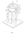
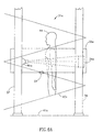
- the pictorial showing of CT system 31 of Fig. 1 is comprised of a CT gantry or ring 32, mounted with its axis vertically disposed. Mounted on the CT ring.are at least one X-ray source 33 and detector apparatus indicated at 34.
- the CT ring 32 is designed to rotate about its axis as it travels vertically downwardly or upwardly.
- both the at least one X-ray source and the oppositely-disposed detectors are connected to the gantry to rotate together about the subject.
- the at least one X-ray source is coupled to the gantry so as to rotate with gantry about the subject; permanently-disposed detectors surround the subject.
- the subject or patient is located within the ring and preferably coextensive with the axis of the ring.
- a plurality of supports or posts slown at 36, 37 and 38 in Fig. 1 support the ring as it rotates about the patient while it moves vertically. More particularly, according to a preferred embodiment, the at least one X-ray source rotates about the patient within the ring which does not rotate.
- the ring with the rotating X-ray source moves vertically.
- both the at least one X-ray source and the oppositely-disposed detectors move within the ring while the ring is moving vertically.
- only the at least one X-ray source rotates within the non-rotating but vertically moving ring.
- the posts have racks that mesh with the gears of gear boxes such as gear boxes indicated at 35a, 35b and 35c, in Figs 1, 4 and 4A.
- the gear boxes are arranged to support the ring 32 on the rack and to cause the ring to move vertically.
- the gear boxes are also arranged to have gears that mesh with a circular rack to cause that rack to rotate.
- the circular rack is attached to the at least one X-ray source 33 to cause the X-ray source to rotate with the ring.
- the at least one X-ray source is attached to the rotating ring 32.
- the detectors 34 are also coupled to the circular rack or to the CT ring, to cause the detectors to rotate with the at least one X-ray source.
- a chamber 43 surrounds and protects the patient as the CT ring 32 moves vertically.
- the diameter of the chamber is smaller than the diameter of the CT ring.
- the system is mounted on and includes a base 41.
- a door to the chamber is provided at 42, enabling access to the chamber 43.
- an outer chamber may be provided which houses the entire system 31, including the support posts, 36, 37 and 38.
- a plurality of posts shown at 36a, 37a and 38a (a fourth post is not seen), support helically-extending rail 40a.
- the ring 32a is mounted on the rail 40a to move in a general vertical direction while rotating about the patient so as to provide a helical motion relative to the subject or patient.
- the helical rotation of the CT ring is provided either by gravity or the movement is motorized.
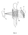
- Fig. 2 is a pictorial showing of the at least one X-ray source 33 and the detector arrangement 34, moving vertically while rotating and providing a helical scan of the subject 44, as described in relation to Fig. 1 or 1A.
- the helical scan trajectory is shown at 46 and is typically generated by an X-ray beam from a single source having a single focal point.
- the detector array 11 of Fig. 2 is shown as having only a single row of detector elements.
- Fig. 3 also illustrates a helical scan, as described in relation to Figs. 1 and 1A.
- a unit is provided wherein the X-ray source 33a contains an X-ray tube having more than one focal point with a multiplicity of X-ray beams emitted by the tube.
- the X-ray source 33a contains an X-ray tube having more than one focal point with a multiplicity of X-ray beams emitted by the tube.
- U.S. Patent 4,689,809 For teachings of CT systems using X-ray sources with multiple focal points, see for example U.S. Patent 4,637,040. While a single source is shown in the figures, it is within the scope of the invention to use multiple X-ray sources such as taught in U.S. Patent 5,966,422.
- an improved detector 34a which includes a multiplicity of rows of detectors, increasing the resolution of the system. While this seems to be a more expensive version, actually, it may reduce the size of the X-ray tube and power supply, and thus the overall cost.
- US Patent 5,228,069. The helical scan trajectory about the subject 44 generated by beams from dual focal points is shown at 46a in Fig. 3.
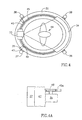
- FIG. 4 The plan view of Fig. 4 shows the CT ring 32 surrounding the patient 44. In this view, the chamber 43 is omitted.
- the X-ray source 33 is oppositely-disposed from detector apparatus 34 to detect the X-rays that have traversed the patient 44.
- the detectors surround the patient and do not rotate, only the X-ray source rotates.
- the ring 32 is affixed to a circular rail 45.
- the at least one X-ray source 33 is affixed to ring 32 either directly or through circular rail 45.
- the detectors 34 are also affixed to the ring 32 either directly or through rail 45.
- the circular rail 45 includes a circular rack 45a attached to the circular rail. Attached to posts 36-39 are vertical racks such as vertical rack 47 shown with post 37, for example.
- the gears of a gear box 35 mesh with rack 47. Either gravity or a motor causes a drive gear 48 that meshes with the gears of the rack to rotate the circular rack 45.
- the circular rack 45 and consequently the ring 32 are caused to rotate during the vertical motion of ring 32 along vertical rack 47 to provide the helical scan.
- the helically-extending rail 40a is affixed to support posts 36a, 37a, 38a and 39a.
- the CT ring 32a is attached to the rail through coupling units 49, 51, 52 and 53.
- the rail includes a helical rack and the coupling units include motorized gears that mesh with the rack and propel the gantry along the helical rails.
- the coupling units include braking arrangements for controlling the descent of the gantry when gravity is used as the motivational force propelling the gantry.
- the gantry is raised by hand or a hoist is used when gravity is the motivating force propelling the gantry along the rails to provide the helical trajectory.
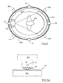
- Fig. 5A is a side schematic view of a rack and gear arrangement for use in controlling the motion of the CT ring 32a on the rail 40a.
- the coupling units such as unit 51 includes a motorized gear 56. It rotates about its axis 57 and meshes with the rack 54 on rail 40a.
- the motorized gear is either powered by a power pack or through the use of brushes as is well known to those skilled in the art.
- Fig. 6 is a side view showing of the screening CT system 31 of Figs 1, 4 and 4A.
- the CT ring 32 does not ride on a helically-arranged rails. Instead, the at least one X-ray source rotates within the ring while the ring moves vertically as indicated by the arrow.
- detectors 34 rotate with the at least one X-ray source within the ring. In fourth generation systems the detectors substantially surround the subject or patient 44 and do not rotate.
- the circular rail 45 with a circular rack 45a attached thereto is shown affixed to the CT ring 32.
- the gears of gear boxes such as gear box 35 mesh with the vertical racks such as rack 47 attached to post.
- gravity causes the rack to drive the gears of the gear boxes such as gear box 35.
- the gears of the gear box then rotate drive gear 48 which meshes with circular rack 45a and causes the at least one X-ray source to rotate while the ring is descending.
- the detectors are also affixed to the circular rack 45 which is attached to the rotating circular rack 45a.
- the rail 45 and rack 45a are shown mounted on ball bearings such as bearing 61 in race 62.
- the gear box is motorized to drive the gears enabling controlled vertical motion in ascending as well as descending directions.
- helical scanning can be accomplished while the CT ring 32 is ascending, as well as while it is descending.
- Fig. 6A is a side view showing of the screening CT system of Figs 1A, 5 and 5A.
- the ring 32a rides on helically-arranged rails 40a.
- the at least one X-ray source 33a and the detectors 34a are fixed to the CT ring which surrounds the patient 44.
- the ring and attached at least one X-ray source are caused to rotate.
- the combined vertical movement along the rails and rotation of the at least one X-ray source around the patient 44a provides a helical scan.
- the detector 34a rotate with the at least one X-ray source.
- the gear coupling between the helically-arranged rail 40a and the CT ring 32a explained in relation to Figs 5 and 5a is represented coupling unit 51.
- Fig. 7 is a block diagram showing of the systems 31 and 31 a.
- a CT ring, or gantry 32 having an X-ray source 33 and a detector arrangement 34 shown disposed oppositely to the X-ray source.
- the ring rotates about the subject while moving vertically to thereby generate the helical scan.
- a system controller is shown at 61 to provide control and timing pulses for the system.
- a high-voltage power supply is indicated at 62.
- the high voltage power supply in accordance with one preferred aspect of the invention comprises a charged battery pack or high-voltage capacitors, located on the ring and indicated at 63.
- the high-voltage capacitors are connected in parallel for charging and in series for use as is known to those skilled in the art.
- the high-voltage power is permanently connected to the ring 32 through a very flexible cable.
- brushes are used in a manner well-known to those skilled in the art.
- the gantry movement system is illustrated at 64. It provides braking when the ring is moved by gravity in the vertical direction, while the at least one X-ray source rotates to provide the helical scan.
- an elevational apparatus is provided for moving the gantry to the top of the posts, to be ready for the next scan.
- This elevational apparatus can be a motorized block and tackle or a hand-operated block, chain and ratchet arrangement.
- view data can be obtained during the vertical motion of the ring, regardless of whether traveling from the bottom of the post to the top of the posts or vice-versa.
- Data acquisition is represented in block 67.
- the acquired data are provided to a memory 50 so that the image processing can be a accomplished at a central locationc n.
- the detectors 34 detect X-ray intensity after the X-rays have traversed the patient. This data are assembled and pre-processed in block 67.
- the pre-processed data are provided to the image reconstruction section indicated at block 68 which operates in conjunction with memory 69 to provide an image in display 71.
- the patient steps into the chamber 43, where he is held still and supported in a standing or sitting position within the ring 32.
- the ring is then directed in a vertical movement downwards either along helically-displaced rails or in a straight vertical displacement while the at least either one X-ray source and detector rotate to provide a helical scan.
- Data are collected during the scan.
- the data are used for reconstructing the image in a well-known manner.
- the screening image is either displayed immediately or the data are recorded in a memory, and the memory is operated on later, for example, in a central location to provide the display.
Landscapes
- Health & Medical Sciences (AREA)
- Life Sciences & Earth Sciences (AREA)
- Engineering & Computer Science (AREA)
- Medical Informatics (AREA)
- Optics & Photonics (AREA)
- Biomedical Technology (AREA)
- Biophysics (AREA)
- High Energy & Nuclear Physics (AREA)
- Veterinary Medicine (AREA)
- Nuclear Medicine, Radiotherapy & Molecular Imaging (AREA)
- Public Health (AREA)
- Pathology (AREA)
- Radiology & Medical Imaging (AREA)
- Physics & Mathematics (AREA)
- Heart & Thoracic Surgery (AREA)
- Molecular Biology (AREA)
- Surgery (AREA)
- Animal Behavior & Ethology (AREA)
- General Health & Medical Sciences (AREA)
- Pulmonology (AREA)
- Theoretical Computer Science (AREA)
- Apparatus For Radiation Diagnosis (AREA)
Applications Claiming Priority (1)
| Application Number | Priority Date | Filing Date | Title |
|---|---|---|---|
| PCT/IL2000/000092 WO2001060258A1 (en) | 2000-02-15 | 2000-02-15 | Clinical screening ct systems |
Publications (2)
| Publication Number | Publication Date |
|---|---|
| EP1257203A1 EP1257203A1 (en) | 2002-11-20 |
| EP1257203B1 true EP1257203B1 (en) | 2004-12-01 |
Family
ID=11042948
Family Applications (1)
| Application Number | Title | Priority Date | Filing Date |
|---|---|---|---|
| EP00903949A Expired - Lifetime EP1257203B1 (en) | 2000-02-15 | 2000-02-15 | Clinical screening ct systems |
Country Status (5)
| Country | Link |
|---|---|
| US (1) | US6735274B1 (enExample) |
| EP (1) | EP1257203B1 (enExample) |
| JP (1) | JP2003522583A (enExample) |
| DE (1) | DE60016467T2 (enExample) |
| WO (1) | WO2001060258A1 (enExample) |
Cited By (1)
| Publication number | Priority date | Publication date | Assignee | Title |
|---|---|---|---|---|
| WO2019140317A1 (en) * | 2018-01-11 | 2019-07-18 | Tek84 Engineering Group, Llc | Compact body scanner |
Families Citing this family (48)
| Publication number | Priority date | Publication date | Assignee | Title |
|---|---|---|---|---|
| US7664543B2 (en) * | 2001-04-26 | 2010-02-16 | Analogic Corporation | CT scanner for and method of imaging a preselected portion of the lower abdomen region of a patient |
| US7099428B2 (en) * | 2002-06-25 | 2006-08-29 | The Regents Of The University Of Michigan | High spatial resolution X-ray computed tomography (CT) system |
| US7356115B2 (en) * | 2002-12-04 | 2008-04-08 | Varian Medical Systems Technology, Inc. | Radiation scanning units including a movable platform |
| US7672426B2 (en) * | 2002-12-04 | 2010-03-02 | Varian Medical Systems, Inc. | Radiation scanning units with reduced detector requirements |
| US7224764B2 (en) * | 2003-08-07 | 2007-05-29 | Xoran Technologies, Inc. | Stand-up CT scanner |
| US7388941B2 (en) * | 2003-08-07 | 2008-06-17 | Xoran Technologies, Inc. | CT extremity scanner |
| US7003070B1 (en) * | 2004-08-03 | 2006-02-21 | William Barry Chen | Upright CT scanner |
| DE102004050172B4 (de) * | 2004-08-20 | 2010-09-02 | "Stiftung Caesar" (Center Of Advanced European Studies And Research) | 3D-Rekonstruktion mit schräger Geometrie |
| US7991242B2 (en) | 2005-05-11 | 2011-08-02 | Optosecurity Inc. | Apparatus, method and system for screening receptacles and persons, having image distortion correction functionality |
| EP1886257A1 (en) | 2005-05-11 | 2008-02-13 | Optosecurity Inc. | Method and system for screening luggage items, cargo containers or persons |
| US7899232B2 (en) | 2006-05-11 | 2011-03-01 | Optosecurity Inc. | Method and apparatus for providing threat image projection (TIP) in a luggage screening system, and luggage screening system implementing same |
| US8494210B2 (en) | 2007-03-30 | 2013-07-23 | Optosecurity Inc. | User interface for use in security screening providing image enhancement capabilities and apparatus for implementing same |
| US7869559B2 (en) * | 2006-10-19 | 2011-01-11 | General Electric Company | X-ray detector methods and apparatus |
| CN101382507A (zh) * | 2007-09-05 | 2009-03-11 | 同方威视技术股份有限公司 | 一种检查航空货运集装箱中违禁物品的装置 |
| US8806914B2 (en) | 2007-09-24 | 2014-08-19 | Freddie R. Brasfield | Target odor detection and security apparatus |
| WO2010044844A1 (en) * | 2008-10-13 | 2010-04-22 | George Papaioannou | Dynamic biplane roentgen stereophotogrammetric analysis |
| US8014490B2 (en) * | 2009-10-20 | 2011-09-06 | Linda Mitchell | Mammogram tender machine |
| US9271689B2 (en) | 2010-01-20 | 2016-03-01 | General Electric Company | Apparatus for wide coverage computed tomography and method of constructing same |
| US9347894B2 (en) * | 2010-09-01 | 2016-05-24 | Spectral Instruments Imaging, LLC | Methods and systems for producing visible light and x-ray image data |
| JP6025849B2 (ja) | 2011-09-07 | 2016-11-16 | ラピスカン システムズ、インコーポレイテッド | マニフェストデータをイメージング/検知処理に統合するx線検査システム |
| DE102012201527B4 (de) * | 2011-10-28 | 2015-10-01 | Siemens Aktiengesellschaft | Vorrichtung zum linearen Verstellen einer Gantry eines Computertomographiegerätes und Computertomographieeinrichtung |
| EP2861148B1 (en) * | 2012-06-14 | 2020-08-19 | Mobius Imaging, LLC | Vertical scan imaging system |
| US10987068B2 (en) | 2012-06-14 | 2021-04-27 | Mobius Imaging Llc | Multi-directional x-ray imaging system |
| US9962132B2 (en) | 2012-06-14 | 2018-05-08 | Mobius Imaging, Llc | Multi-directional X-ray imaging system with single support column |
| DE102012216858A1 (de) * | 2012-09-20 | 2014-03-20 | Siemens Aktiengesellschaft | Verfahrbare Gantry |
| WO2015054466A1 (en) * | 2013-10-10 | 2015-04-16 | Carestream Health, Inc. | Extremity imaging for animals |
| CN103549970B (zh) * | 2013-10-30 | 2015-08-26 | 沈阳东软医疗系统有限公司 | 一种医用ct机 |
| DE102014207568A1 (de) * | 2014-04-22 | 2015-10-22 | Siemens Aktiengesellschaft | Röntgenvorrichtung |
| CN104198506B (zh) * | 2014-08-27 | 2017-11-07 | 清华大学 | 小角度自摆式大型多层螺旋ct设备和检查方法 |
| WO2017106113A1 (en) | 2015-12-15 | 2017-06-22 | Carestream Health, Inc. | Volumetric imaging system for health screening |
| JP6779303B2 (ja) * | 2016-02-10 | 2020-11-04 | イオス・イメージング | 患者の器官のx線撮影の方法 |
| CN109074889B (zh) | 2016-02-22 | 2022-10-18 | 拉皮斯坎系统股份有限公司 | 用于检测货物中的危险品和违禁品的系统和方法 |
| US10524740B2 (en) * | 2016-04-11 | 2020-01-07 | Dedicated2Imaging, Llc. | Self-contained low cost CT systems with integrated drive system |
| US10307120B1 (en) * | 2016-09-07 | 2019-06-04 | Prescient Imaging, LLC | Vertical moving horizontal aperture ring positron emission tomography scanner and chair with stationary cycle for stressing the patient's heart |
| US10624596B2 (en) * | 2016-11-23 | 2020-04-21 | Mobius Imaging, Llc | Cantilevered x-ray CT system for multi-axis imaging |
| JP6958851B2 (ja) * | 2017-02-01 | 2021-11-02 | キヤノンメディカルシステムズ株式会社 | X線コンピュータ断層撮影装置 |
| JP6912769B2 (ja) * | 2017-02-16 | 2021-08-04 | キヤノンメディカルシステムズ株式会社 | X線コンピュータ断層撮影装置 |
| US11808912B2 (en) | 2018-01-11 | 2023-11-07 | Tek84 Inc. | Compact body scanner |
| CN109528223B (zh) * | 2018-12-12 | 2022-05-20 | 中国科学院苏州生物医学工程技术研究所 | 一种立式ct扫描仪 |
| CN109620169B (zh) * | 2019-01-31 | 2021-12-14 | 温州大学 | 一种智能制造技术的综合实践教学系统 |
| WO2021006166A1 (ja) * | 2019-07-09 | 2021-01-14 | 雫石 誠 | コンピュータトモグラフィー装置及び検診車両 |
| US11786196B2 (en) * | 2020-06-08 | 2023-10-17 | GE Precision Healthcare LLC | Systems and methods for a stationary CT imaging system |
| JP7580219B2 (ja) * | 2020-07-31 | 2024-11-11 | キヤノンメディカルシステムズ株式会社 | 医用画像診断装置 |
| GB202016906D0 (en) * | 2020-10-24 | 2020-12-09 | Scintacor Ltd | An irradiation apparatus |
| JP7612505B2 (ja) * | 2021-04-28 | 2025-01-14 | 富士フイルム株式会社 | 医用画像撮影装置 |
| JP7589104B2 (ja) * | 2021-04-28 | 2024-11-25 | 富士フイルム株式会社 | 医用画像撮影装置、医用画像撮影装置の作動方法、医用画像撮影装置の作動プログラム |
| CN113476069B (zh) * | 2021-07-27 | 2023-05-12 | 赛诺威盛科技(北京)股份有限公司 | Ct扫描装置和ct扫描系统 |
| CN113456102A (zh) * | 2021-07-27 | 2021-10-01 | 赛诺威盛科技(北京)股份有限公司 | 扫描升降机构、ct扫描装置和ct扫描系统 |
Family Cites Families (17)
| Publication number | Priority date | Publication date | Assignee | Title |
|---|---|---|---|---|
| US4298800A (en) | 1978-02-27 | 1981-11-03 | Computome Corporation | Tomographic apparatus and method for obtaining three-dimensional information by radiation scanning |
| US4689809A (en) | 1982-11-23 | 1987-08-25 | Elscint, Inc. | X-ray tube having an adjustable focal spot |
| US4637040A (en) | 1983-07-28 | 1987-01-13 | Elscint, Ltd. | Plural source computerized tomography device with improved resolution |
| US4829549A (en) | 1985-06-19 | 1989-05-09 | Vogel John M | Densitometer for scanning os calcis for predicting osteoporosis |
| JPH084586B2 (ja) * | 1989-02-07 | 1996-01-24 | 浜松ホトニクス株式会社 | Ct装置 |
| IL90521A0 (en) | 1989-06-04 | 1990-01-18 | Elscint Ltd | Dual slice scanner |
| US5042487A (en) | 1989-11-13 | 1991-08-27 | Marquardt Mark R | Examination unit including positionable patient chair, examination device and support system |
| EP0495137A1 (de) * | 1991-01-15 | 1992-07-22 | Siemens Aktiengesellschaft | Computertomograph |
| DE4103588C1 (enExample) * | 1991-02-06 | 1992-05-27 | Siemens Ag, 8000 Muenchen, De | |
| US5170439A (en) | 1991-06-11 | 1992-12-08 | Picker International, Inc. | Cone beam reconstruction using combined circle and line orbits |
| US5305363A (en) | 1992-01-06 | 1994-04-19 | Picker International, Inc. | Computerized tomographic scanner having a toroidal x-ray tube with a stationary annular anode and a rotating cathode assembly |
| US5966422A (en) | 1992-07-20 | 1999-10-12 | Picker Medical Systems, Ltd. | Multiple source CT scanner |
| DE4405505A1 (de) * | 1994-02-21 | 1995-08-31 | Siemens Ag | Computertomograph |
| US5708691A (en) * | 1996-07-05 | 1998-01-13 | Kabushiki Kaisha Toshiba | X-ray computed tomographic imaging device and x-ray computed tomographic method |
| US5862198A (en) | 1997-09-30 | 1999-01-19 | Siemens Corporate Research, Inc. | Pre-calculated hitlist for reducing run-time processing of an exact cone beam reconstruction algorithm |
| US6463122B1 (en) * | 2000-08-21 | 2002-10-08 | Bio-Imaging Resource, Inc. | Mammography of computer tomography for imaging and therapy |
| US6459756B1 (en) * | 2001-10-30 | 2002-10-01 | Siemens Corporate Research, Inc. | System and method for providing normalization correction for image reconstruction in a reduced pitch spiral scan cone beam computed tomography imaging system |
-
2000
- 2000-02-15 US US10/182,786 patent/US6735274B1/en not_active Expired - Fee Related
- 2000-02-15 DE DE60016467T patent/DE60016467T2/de not_active Expired - Lifetime
- 2000-02-15 JP JP2001559359A patent/JP2003522583A/ja active Pending
- 2000-02-15 EP EP00903949A patent/EP1257203B1/en not_active Expired - Lifetime
- 2000-02-15 WO PCT/IL2000/000092 patent/WO2001060258A1/en not_active Ceased
Cited By (1)
| Publication number | Priority date | Publication date | Assignee | Title |
|---|---|---|---|---|
| WO2019140317A1 (en) * | 2018-01-11 | 2019-07-18 | Tek84 Engineering Group, Llc | Compact body scanner |
Also Published As
| Publication number | Publication date |
|---|---|
| JP2003522583A (ja) | 2003-07-29 |
| DE60016467T2 (de) | 2005-11-03 |
| EP1257203A1 (en) | 2002-11-20 |
| WO2001060258A1 (en) | 2001-08-23 |
| US6735274B1 (en) | 2004-05-11 |
| DE60016467D1 (de) | 2005-01-05 |
Similar Documents
| Publication | Publication Date | Title |
|---|---|---|
| EP1257203B1 (en) | Clinical screening ct systems | |
| US7003070B1 (en) | Upright CT scanner | |
| EP2863803B1 (en) | Multi-plane x-ray imaging system and method | |
| US8891726B2 (en) | Multiple-source imaging system with flat-panel detector | |
| EP2642924B1 (en) | Computed tomography and tomosynthesis system | |
| CN105188542B (zh) | 用于锥形束计算机断层摄影的肢体成像装置 | |
| EP0948930B1 (en) | Acquiring volumetric image data | |
| US6904119B2 (en) | Radiographic apparatus | |
| US11617557B2 (en) | Fast 3D radiography using multiple pulsed X-ray sources in motion with C-arm | |
| EP1605826B1 (en) | Computerized tomographic imaging system | |
| US20050135560A1 (en) | Portable computed tomography scanner and methods thereof | |
| US7596205B2 (en) | X-ray hybrid diagnosis system | |
| US9480440B2 (en) | System and method for cone beam computed tomography | |
| JP5905694B2 (ja) | 広いカバー範囲及び低線量での心ct撮像のための動的コリメータを備えた計算機式断層写真法スキャナ | |
| CN109770934A (zh) | 一种立式ct成像系统 | |
| JP2004065982A (ja) | 周期的に運動する検査対象物の画像を撮影する画像式医用検査装置および周期的に運動する検査対象物の3次元測定データの取得方法 | |
| US11253211B2 (en) | System and method for utilizing an X-ray imaging system having a hybrid detector | |
| JP2004141656A (ja) | 断層撮影装置 |
Legal Events
| Date | Code | Title | Description |
|---|---|---|---|
| PUAI | Public reference made under article 153(3) epc to a published international application that has entered the european phase |
Free format text: ORIGINAL CODE: 0009012 |
|
| 17P | Request for examination filed |
Effective date: 20020913 |
|
| AK | Designated contracting states |
Kind code of ref document: A1 Designated state(s): AT BE CH CY DE DK ES FI FR GB GR IE IT LI LU MC NL PT SE |
|
| GRAP | Despatch of communication of intention to grant a patent |
Free format text: ORIGINAL CODE: EPIDOSNIGR1 |
|
| RAP1 | Party data changed (applicant data changed or rights of an application transferred) |
Owner name: KONINKLIJKE PHILIPS ELECTRONICS N.V. |
|
| GRAS | Grant fee paid |
Free format text: ORIGINAL CODE: EPIDOSNIGR3 |
|
| GRAA | (expected) grant |
Free format text: ORIGINAL CODE: 0009210 |
|
| RIN1 | Information on inventor provided before grant (corrected) |
Inventor name: ZAHAVI, OPHER Inventor name: LEVENE, SIMHA |
|
| AK | Designated contracting states |
Kind code of ref document: B1 Designated state(s): DE FR IT NL |
|
| PG25 | Lapsed in a contracting state [announced via postgrant information from national office to epo] |
Ref country code: IT Free format text: LAPSE BECAUSE OF FAILURE TO SUBMIT A TRANSLATION OF THE DESCRIPTION OR TO PAY THE FEE WITHIN THE PRESCRIBED TIME-LIMIT;WARNING: LAPSES OF ITALIAN PATENTS WITH EFFECTIVE DATE BEFORE 2007 MAY HAVE OCCURRED AT ANY TIME BEFORE 2007. THE CORRECT EFFECTIVE DATE MAY BE DIFFERENT FROM THE ONE RECORDED. Effective date: 20041201 Ref country code: NL Free format text: LAPSE BECAUSE OF FAILURE TO SUBMIT A TRANSLATION OF THE DESCRIPTION OR TO PAY THE FEE WITHIN THE PRESCRIBED TIME-LIMIT Effective date: 20041201 |
|
| REG | Reference to a national code |
Ref country code: IE Ref legal event code: FG4D |
|
| REF | Corresponds to: |
Ref document number: 60016467 Country of ref document: DE Date of ref document: 20050105 Kind code of ref document: P |
|
| NLV1 | Nl: lapsed or annulled due to failure to fulfill the requirements of art. 29p and 29m of the patents act | ||
| PLBE | No opposition filed within time limit |
Free format text: ORIGINAL CODE: 0009261 |
|
| STAA | Information on the status of an ep patent application or granted ep patent |
Free format text: STATUS: NO OPPOSITION FILED WITHIN TIME LIMIT |
|
| ET | Fr: translation filed | ||
| 26N | No opposition filed |
Effective date: 20050902 |
|
| REG | Reference to a national code |
Ref country code: FR Ref legal event code: D6 |
|
| PGFP | Annual fee paid to national office [announced via postgrant information from national office to epo] |
Ref country code: FR Payment date: 20090227 Year of fee payment: 10 |
|
| PGFP | Annual fee paid to national office [announced via postgrant information from national office to epo] |
Ref country code: DE Payment date: 20100430 Year of fee payment: 11 |
|
| REG | Reference to a national code |
Ref country code: FR Ref legal event code: ST Effective date: 20101029 |
|
| PG25 | Lapsed in a contracting state [announced via postgrant information from national office to epo] |
Ref country code: FR Free format text: LAPSE BECAUSE OF NON-PAYMENT OF DUE FEES Effective date: 20100301 |
|
| REG | Reference to a national code |
Ref country code: DE Ref legal event code: R119 Ref document number: 60016467 Country of ref document: DE Effective date: 20110901 |
|
| PG25 | Lapsed in a contracting state [announced via postgrant information from national office to epo] |
Ref country code: DE Free format text: LAPSE BECAUSE OF NON-PAYMENT OF DUE FEES Effective date: 20110901 |