EP1256730A2 - Biegeeinstellwalzewälzlager - Google Patents
Biegeeinstellwalzewälzlager Download PDFInfo
- Publication number
- EP1256730A2 EP1256730A2 EP02008891A EP02008891A EP1256730A2 EP 1256730 A2 EP1256730 A2 EP 1256730A2 EP 02008891 A EP02008891 A EP 02008891A EP 02008891 A EP02008891 A EP 02008891A EP 1256730 A2 EP1256730 A2 EP 1256730A2
- Authority
- EP
- European Patent Office
- Prior art keywords
- roller
- yoke
- bearing
- sealing
- roller according
- Prior art date
- Legal status (The legal status is an assumption and is not a legal conclusion. Google has not performed a legal analysis and makes no representation as to the accuracy of the status listed.)
- Granted
Links
- 238000007789 sealing Methods 0.000 claims abstract description 45
- 239000000314 lubricant Substances 0.000 claims abstract description 18
- 238000005096 rolling process Methods 0.000 claims description 29
- 239000002826 coolant Substances 0.000 claims description 21
- 238000005452 bending Methods 0.000 claims description 6
- 239000012530 fluid Substances 0.000 abstract description 2
- 239000012809 cooling fluid Substances 0.000 abstract 1
- 239000003921 oil Substances 0.000 description 27
- 239000010687 lubricating oil Substances 0.000 description 19
- 238000001816 cooling Methods 0.000 description 13
- 241000283216 Phocidae Species 0.000 description 9
- 230000002706 hydrostatic effect Effects 0.000 description 4
- 230000000694 effects Effects 0.000 description 3
- 239000007788 liquid Substances 0.000 description 3
- 230000036316 preload Effects 0.000 description 2
- 230000000712 assembly Effects 0.000 description 1
- 238000000429 assembly Methods 0.000 description 1
- 230000001419 dependent effect Effects 0.000 description 1
- 230000002349 favourable effect Effects 0.000 description 1
- 239000000463 material Substances 0.000 description 1
- 238000012986 modification Methods 0.000 description 1
- 230000004048 modification Effects 0.000 description 1
- 230000002093 peripheral effect Effects 0.000 description 1
- 238000000926 separation method Methods 0.000 description 1
Images

Classifications
-
- F—MECHANICAL ENGINEERING; LIGHTING; HEATING; WEAPONS; BLASTING
- F16—ENGINEERING ELEMENTS AND UNITS; GENERAL MEASURES FOR PRODUCING AND MAINTAINING EFFECTIVE FUNCTIONING OF MACHINES OR INSTALLATIONS; THERMAL INSULATION IN GENERAL
- F16C—SHAFTS; FLEXIBLE SHAFTS; ELEMENTS OR CRANKSHAFT MECHANISMS; ROTARY BODIES OTHER THAN GEARING ELEMENTS; BEARINGS
- F16C13/00—Rolls, drums, discs, or the like; Bearings or mountings therefor
- F16C13/02—Bearings
- F16C13/022—Bearings supporting a hollow roll mantle rotating with respect to a yoke or axle
- F16C13/024—Bearings supporting a hollow roll mantle rotating with respect to a yoke or axle adjustable for positioning, e.g. radial movable bearings for controlling the deflection along the length of the roll mantle
- F16C13/026—Bearings supporting a hollow roll mantle rotating with respect to a yoke or axle adjustable for positioning, e.g. radial movable bearings for controlling the deflection along the length of the roll mantle by fluid pressure
- F16C13/028—Bearings supporting a hollow roll mantle rotating with respect to a yoke or axle adjustable for positioning, e.g. radial movable bearings for controlling the deflection along the length of the roll mantle by fluid pressure with a plurality of supports along the length of the roll mantle, e.g. hydraulic jacks
-
- F—MECHANICAL ENGINEERING; LIGHTING; HEATING; WEAPONS; BLASTING
- F16—ENGINEERING ELEMENTS AND UNITS; GENERAL MEASURES FOR PRODUCING AND MAINTAINING EFFECTIVE FUNCTIONING OF MACHINES OR INSTALLATIONS; THERMAL INSULATION IN GENERAL
- F16C—SHAFTS; FLEXIBLE SHAFTS; ELEMENTS OR CRANKSHAFT MECHANISMS; ROTARY BODIES OTHER THAN GEARING ELEMENTS; BEARINGS
- F16C13/00—Rolls, drums, discs, or the like; Bearings or mountings therefor
- F16C13/02—Bearings
Definitions
- the invention relates to a bending roller with a Roller jacket, which is lubricated with the help of liquid Rolling bearings rotatably supported on a yoke is, in addition to at least one rolling bearing, a sealing arrangement arranged with a coolant supply is.
- Such bending adjustment rollers which are also used as deflection compensation rollers are referred to in the Usually as a top and / or bottom roller in a roller stack of a calender with which a paper web is used or a comparable material web with increased Pressure is applied.
- the roller shell is thereby in the press direction of the roll stack of hydrostatic Support elements supported.
- the rotary bearing of the roller shell in relation to the yoke takes place via the roller bearings mentioned.
- the roller bearings are continuously lubricated during operation, i.e. a lubricating oil is supplied to them.
- a lubricating oil is supplied to them.
- sealing arrangements are provided that the from Roller shell enclosed cavity axially outwards caulk. Because the seal assemblies are moving parts sealing against each other may arise considerable frictional heat, which can be Coolant, usually also an oil, removed must become.
- the invention is based, wear to prevent the rolling bearings.
- This task is the initially mentioned type in that for a Lubricant flow from the roller bearings is a first disposal path is provided by a second disposal path for one. Coolant flow from the Sealing arrangement is separated.
- this arrangement has the advantage that the lubricant flow, i.e. the circulation of the Lubricating oil, and the coolant flow, i.e. the circulation of the coolant can be handled separately. you can, for example, ensure that the coolant flow is cooled differently than the lubricant flow. This can create favorable conditions and, for example, the viscosity of the lubricating oil better to adjust.
- a removal device is preferably in the first disposal path intended.
- the discharge device is preferably a scoop educated.
- a creator is known per se.
- Creators are used to create an oil layer, which are on the inside of the circumferential roller shell forms to skim.
- the oil adhering to the roller jacket is in the Creator pushed in with a pressure that is sufficient to deliver the lubricating oil radially inwards.
- the creator two has mutually opposite openings which in Direction of rotation of the roll shell are directed and the are connected to a drain line, between a pivotable flap is arranged in both openings is that at pressure in one opening the other Closes the opening.
- Lubricating oil can basically be obtained through any of the flow into the creator through both openings. Which Opening ultimately used depends on the Direction of rotation of the roll shell. The lubricating oil flows into the opening of the creator, that of the direction of rotation is directed against. The inflowing oil creates now press the flap, the flap pivoted and thus closes the other opening.
- the discharge device preferably conveys lubricant at least down to a level that is radially outside the rolling element of the rolling bearing lies. It is it is not necessary to completely discharge the lubricating oil. In many cases, this would only be relative with one great technical effort possible. You care but for making the creator the lubricant so far promotes that it is not the rolling elements of the rolling bearing can apply more, but only on the outer ring of the rolling bearing presses.
- the sealing arrangement has one with the Yoke connected sealing ring with a radially outward protruding sealing lip.
- the sealing lip works with you Flange together, which is attached to the roll shell and extends substantially parallel to the roll shell. If you look at the seal assembly this way trains, then the seal assembly only needs a comparatively small space. So it stands enough space available to the two disposal paths to run separately.
- the radially outward protruding sealing lip has the advantage that the sealing effect with increasing speed of the roller jacket in Basically does not change.
- the seal assembly one with the roll shell connected sealing ring with a radially inward protruding sealing lip, wherein clamping means are provided, the sealing lip against a flange preload on the yoke. If the sealing ring with the roller jacket rotates, then the sealing lip tilts with increasing Speeds to lift off the flange on the yoke. This leaves the sealing effect of the sealing ring with increasing Speeds after. You can now either do one Accept conditional leakage or you can Provide clamping devices that seal the sealing lip against the Preload flange on yoke. These clamping devices can Be spring elements, the sealing lip on the flange pull or push. But you can also get hydraulic Imagine clamping devices with a pressure on the radial outside of the sealing lip is built up, around the sealing lip radially inwards against the flange to press.
- At least one of the two disposal paths preferably has a channel in a pipe that a gap between the yoke and a bearing bracket bridged.
- the camp and the Sealing arrangement not directly mounted on the yoke, but on a bearing bracket. You can now get one Form the disposal path in that the corresponding Oil in the gap between the bearing bracket and the The yoke drains away and can be carried away from there can. So that there is mutual interference with the oil does not take place from the other disposal path this oil through the pipe from the bearing bracket into the yoke guided.
- the tube in the yoke and / or is mounted telescopically in the bearing bracket.
- This configuration is particularly the case with rollers Jacking stroke preferred, where the bearing bracket opposite the yoke is movable. In this case, by the tube the changing distance between the bearing bracket and bridged the yoke.
- a lubricant chamber is one Forms part of the first supply path, and one Coolant chamber, which is part of the second disposal path forms by a labyrinth seal from each other Cut.
- Both the lubricant chamber the is adjacent to the rolling bearing, as well as the coolant chamber, which is adjacent to the sealing arrangement limited on the one hand by parts that are stationary to the Yoke are arranged, and on the other hand by parts that rotate with the roller shell. So you have to have one appropriate seal between moving against each other Provide parts that separate the lubricant chamber from the Coolant chamber separates.
- Such a seal leaves through a labyrinth seal realize.
- a labyrinth seal is not tight in the hermetic sense, i.e. it leaves fluid from a higher pressure room to a lower room Pressure exceeded. The amount of liquid is so small that the pressure ratios in the respective Chambers not significantly negatively affected.
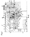
- Fig. 1 shows schematically a bearing arrangement on a axial end of a bend adjustment roller 1.
- the bend adjustment roller 1 has a yoke 2, which has a roll shell 3 penetrates, which is designed as a tube.
- On the The peripheral surface of the roll shell 3 is an elastic one Covering 4 arranged.
- hydrostatic support elements 5 which support the roll shell 3 with respect to the yoke 2.
- these support elements 5 are only able to To absorb forces that act in one press direction.
- the roll shell 3 is rotatable relative to the yoke 2 stored. This is between the yoke 2 and the Rolling jacket 3, a roller bearing 6 is provided, the one Has inner ring 7, rolling elements 8 and an outer ring 9.
- the rolling elements 8 are not yet closer by one shown cage with each other in the circumferential direction connected. In the present case it is a Spherical roller bearings.
- the rolling bearing 6 is lubricated with lubricating oil, which is about a lubricating oil channel 11 is supplied, which consists of a Groove 12 fed on the radial inside of the inner ring 7 becomes.
- the lubricating oil flows axially to both Pages from.
- the roller bearing 6 is arranged on a bearing bracket 13, opposite in the effective direction of the support elements 5 the yoke 2 is movable.
- the bending adjustment roller is accordingly 1 as a roller with a jacket stroke educated.
- Lubricant chamber 10 On the axial outside of the rolling bearing 6 is one Lubricant chamber 10 arranged by the rolling bearing 6, the bearing bracket 13 and a flange bracket 15 is limited, which is attached to the roll shell 3 and rotates with this. Another limitation is given by a creator carrier 16 formed with a radial wall 17 of the flange carrier 15, the radially inward protrudes, forms a labyrinth seal 18.
- a creator 19 is attached to the creator support 16, the upper part in Fig. 2 in an enlarged view is shown.
- a drain pipe 20 provided in a channel in the bearing bracket 13 continues, which opens into the intermediate space 14.
- the Gap 14 is in a manner not shown connected to a return line for the lubricating oil.
- the creator 19 shown in Fig. 2 has a head 22 in which two openings 23, 24 are provided, each directed in the direction of rotation of the roll shell are and connected to the drain line 20 are. Between the two openings 23, 24 is one Flap 25 arranged, the on an axis of rotation 26 on Head is pivotally mounted, from the with solid lines shown in a position First position shown in dashed lines, in which the Opening 24 closes when pressure at opening 23 arises, and shown in a dash-dotted line second position, in which it closes the opening 23, if lubricating oil is present under pressure at the opening 24. Switching the scoop 19 becomes dependent reached by the direction of rotation of the roll shell 3 without any external intervention.
- a flange 27 is arranged on the radial wall 17 extends essentially parallel to the roll shell 3.
- a sealing ring 28 interacts with the flange 27, which has a radially outward sealing lip 29 has that on the radial inner side of the flange 27 is present.
- the flange 27, the sealing ring 28, the bearing bracket 13 and the creator carrier 16 limit together a coolant chamber 30 which has a supply connection 31, by the cooling oil under pressure against the sealing lip 29 can be promoted by this an arrow 32 is symbolized.
- the cooling oil fills the Coolant chamber 30 completely out, so that the supplied Cooling oil that is present in the coolant chamber 30 Cooling oil displaced through an opening 33 in the bearing bracket 13 is formed. From there it gets Cooling oil through a tube 34 that telescopes in the bearing bracket 13 is guided and bridges the gap 14, in the yoke 2, where it via lines not shown can be dissipated.
- Lubricating oil which in an amount of about 2 l / min Rolling bearing 6 is supplied, enters the lubricant chamber 10 and is from there with the help of the Creator 19 promoted.
- the creator 19 is oriented so that he is the oil that is due to the centrifugal force collects on the inside of the flange carrier 15, skims, and above a level at which the Oil located there act on the rolling elements 8 can.
- the rolling elements 8 are therefore not one Pressure in the lubricant chamber 10 loaded. Builds there basically no pressure at all.
- the cooling oil on the other hand, with a quantity of about 10 l / min in the coolant chamber 30 is conveyed in a separate supply path through the Tube 34 back into the yoke.
- the circuits of cooling oil and Lubricating oils are therefore in any case in the immediate vicinity Decoupled from the vicinity of the bearing 6.
- the sealing arrangement has a sealing ring 28th used with a radially outwardly projecting sealing lip 29, builds the sealing arrangement very small. Thereby is an enlarged space axially outside of Rolling bearing available, which one for the separation of Can use cooling oil and lubricating oil.
- the Bending adjustment roller is no longer designed as a jacketed roller.
- the roller bearing 6 is without an intermediate Bearing bracket firmly mounted on the yoke 2. Accordingly can the oil skimmed by the creator 19 convey directly into a return channel 35.
- the coolant chamber 30 is directly with a drain channel 36 connected. There is also an inlet channel 37 provided via the cooling oil into the coolant chamber 30 is promoted. Otherwise, the mode of action is this Bearing arrangement comparable to that of FIG. 1.
Landscapes
- Engineering & Computer Science (AREA)
- General Engineering & Computer Science (AREA)
- Mechanical Engineering (AREA)
- Physics & Mathematics (AREA)
- Fluid Mechanics (AREA)
- Rolling Contact Bearings (AREA)
- Sealing Of Bearings (AREA)
- Rolls And Other Rotary Bodies (AREA)
- Casting Or Compression Moulding Of Plastics Or The Like (AREA)
Abstract
Description
- Fig. 1
- eine erste Ausführungsform einer Lageranordnung,
- Fig. 2
- einen Schritt A-A durch einen Schöpfer nach Fig. 1 und
- Fig. 3
- eine zweite Ausführungsform einer Lageranordnung.
Claims (10)
- Biegeeinstellwalze mit einem Walzenmantel, der mit Hilfe von flüssigkeitsgeschmierten Wälzlagern drehbar auf einem Joch gelagert ist, wobei neben mindestens einem Wälzlager eine Dichtungsanordnung mit einer Kühlflüssigkeitsversorgung angeordnet ist, dadurch gekennzeichnet, daß für einen Schmiermittelstrom von dem Wälzlager (6) ein erster Entsorgungspfad (10, 19, 20, 21) vorgesehen ist, der von einem zweiten Entsorgungspfad (30, 33, 34) für einen Kühlflüssigkeitsstrom von der Dichtungsanordnung (28) getrennt ist.
- Walze nach Anspruch 1, dadurch gekennzeichnet, daß im ersten Entsorgungspfad (10, 19, 20, 21) eine Abfördereinrichtung (19) vorgesehen ist.
- Walze nach Anspruch 2, dadurch gekennzeichnet, daß die Abfördereinrichtung als Schöpfer (19) ausgebildet ist.
- Walze nach Anspruch 3, dadurch gekennzeichnet, daß der Schöpfer (19) zwei einander entgegengesetzte Öffnungen (23, 24) aufweist, die Drehrichtung des Walzenmantels (3) gerichtet sind und die mit einer Abflußleitung (20) verbunden sind, wobei zwischen beiden Öffnungen (23, 24) eine verschwenkbare Klappe (25) angeordnet ist, die bei Druck in einer Öffnung (23, 24) die jeweils andere Öffnung (24, 23) verschließt.
- Walze nach einem der Ansprüche 2 bis 4, dadurch gekennzeichnet, daß die Abfördereinrichtung (19) Schmiermittel zumindest bis zu einem Pegel abfördert, der radial außerhalb der Wälzkörper (8) des Wälzlagers (6) liegt.
- Walze nach einem der Ansprüche 1 bis 5, dadurch gekennzeichnet, daß die Dichtungsanordnung einen mit dem Joch (2) verbundenen Dichtring (28) mit einer radial nach außen ragenden Dichtlippe (29) aufweist.
- Walze nach einem der Ansprüche 1 bis 5, dadurch gekennzeichnet, daß die Dichtungsanordnung einen mit dem Walzenmantel verbundenen Dichtring mit einer radial nach innen ragenden Dichtlippe aufweist, wobei Spannmittel vorgesehen sind, die die Dichtlippe gegen einen Flansch am Joch vorspannen.
- Walze nach einem der Ansprüche 1 bis 7, dadurch gekennzeichnet, daß mindestens einer der beiden Entsorgungspfade einen in einem Rohr (34) geführten Kanal aufweist, das einen Spalt (14) zwischen dem Joch (2) und einem Lagerträger (13) überbrückt.
- Walze nach Anspruch 8, dadurch gekennzeichnet, daß das Rohr (34) im Joch (2) und/oder im Lagerträger (13) teleskopierend gelagert ist.
- Walze nach einem der Ansprüche 1 bis 8, dadurch gekennzeichnet, daß eine Schmiermittelkammer (10), die einen Teil des ersten Entsorgungspfades bildet, und eine Kühlmittelkammer (30), die einen Teil des zweiten Entsorgungspfades bildet, durch eine Labyrinthdichtung (18) voneinander getrennt sind.
Applications Claiming Priority (2)
| Application Number | Priority Date | Filing Date | Title |
|---|---|---|---|
| DE10122649A DE10122649C2 (de) | 2001-05-10 | 2001-05-10 | Biegeeinstellwalze |
| DE10122649 | 2001-05-10 |
Publications (3)
| Publication Number | Publication Date |
|---|---|
| EP1256730A2 true EP1256730A2 (de) | 2002-11-13 |
| EP1256730A3 EP1256730A3 (de) | 2005-07-13 |
| EP1256730B1 EP1256730B1 (de) | 2010-01-13 |
Family
ID=7684244
Family Applications (1)
| Application Number | Title | Priority Date | Filing Date |
|---|---|---|---|
| EP02008891A Expired - Lifetime EP1256730B1 (de) | 2001-05-10 | 2002-04-20 | Biegeeinstellwalzewälzlager |
Country Status (3)
| Country | Link |
|---|---|
| US (1) | US6840678B2 (de) |
| EP (1) | EP1256730B1 (de) |
| DE (2) | DE10122649C2 (de) |
Families Citing this family (3)
| Publication number | Priority date | Publication date | Assignee | Title |
|---|---|---|---|---|
| DE102006024832B4 (de) * | 2006-05-24 | 2013-07-18 | Andritz Küsters Gmbh | Durchbiegungssteuerbare Walze |
| DE102006025247A1 (de) * | 2006-05-29 | 2007-12-06 | Andritz Küsters GmbH & Co. KG | Walze |
| RU2320771C1 (ru) * | 2006-07-06 | 2008-03-27 | Институт проблем сверхпластичности металлов РАН | Способ изготовления листового полуфабриката из титанового сплава |
Family Cites Families (11)
| Publication number | Priority date | Publication date | Assignee | Title |
|---|---|---|---|---|
| CH606604A5 (de) * | 1975-11-04 | 1978-11-15 | Escher Wyss Ag | |
| DE2920528B2 (de) * | 1979-05-15 | 1981-03-19 | Escher Wyss Gmbh, 7980 Ravensburg | Durchbiegungseinstellwalze |
| DE3526283A1 (de) * | 1985-07-23 | 1987-02-05 | Kleinewefers Gmbh | Durchbiegungssteuerbare und beheizbare walze |
| DE3607729C3 (de) * | 1986-03-08 | 1995-06-29 | Skf Gmbh | Wälzlagerung, für Arbeitswalzen in Hochgeschwindigkeitswalzwerken |
| DE3730153C3 (de) * | 1987-09-09 | 1996-04-11 | Kuesters Eduard Maschf | Walze |
| US5010633A (en) * | 1990-06-21 | 1991-04-30 | Beloit Corporation | Controlled deflection roll with heat barrier |
| DE4107440C2 (de) * | 1991-03-08 | 1993-12-02 | Kleinewefers Gmbh | Durchbiegungssteuerbare und beheizbare Walze |
| DE4202373C1 (en) * | 1992-01-29 | 1993-04-22 | Eduard Kuesters Maschinenfabrik Gmbh & Co. Kg, 4150 Krefeld, De | Roll acting against temp. deviations at end of tempered roll - has spray device on crosshead in area of at least one of working rolls |
| DE9218151U1 (de) * | 1992-08-12 | 1993-11-04 | Sulzer Papertec Krefeld Gmbh, 47803 Krefeld | Durchbiegungssteuerbare und beheizbare Hohlwalze, insbesondere für Kalander |
| DE4428420C2 (de) * | 1994-08-11 | 1996-09-19 | Kleinewefers Ramisch Gmbh | Walze zur Druckbehandlung von Warenbahnen |
| IT1279895B1 (it) * | 1995-12-22 | 1997-12-18 | Deublin Sint S R L | Dispositivo per introdurre un fluido ad elevata temperatura in un corpo rotante |
-
2001
- 2001-05-10 DE DE10122649A patent/DE10122649C2/de not_active Expired - Fee Related
-
2002
- 2002-04-20 DE DE50214157T patent/DE50214157D1/de not_active Expired - Lifetime
- 2002-04-20 EP EP02008891A patent/EP1256730B1/de not_active Expired - Lifetime
- 2002-04-26 US US10/132,564 patent/US6840678B2/en not_active Expired - Fee Related
Non-Patent Citations (1)
| Title |
|---|
| None |
Also Published As
| Publication number | Publication date |
|---|---|
| DE50214157D1 (de) | 2010-03-04 |
| EP1256730A3 (de) | 2005-07-13 |
| US20020168123A1 (en) | 2002-11-14 |
| DE10122649A1 (de) | 2002-11-21 |
| DE10122649C2 (de) | 2003-07-03 |
| US6840678B2 (en) | 2005-01-11 |
| EP1256730B1 (de) | 2010-01-13 |
Similar Documents
| Publication | Publication Date | Title |
|---|---|---|
| DE3876663T2 (de) | Oelfilmlager und buchse. | |
| AT513507B1 (de) | Gleitlagerpaket | |
| DE102008055793B3 (de) | Vorrichtung zur Abdichtung einer mit einem flüssigen Schmiermittel geschmierten Lagerung | |
| EP3794244B1 (de) | Doppelkupplungseinheit und antriebsanordnung mit einer solchen doppelkupplungseinheit | |
| WO2001066983A1 (de) | Labyrinthdichtung zwischen drehbaren bauteilen | |
| EP3091242A1 (de) | Gleitlager mit schmiernut | |
| EP2953243A1 (de) | Vorrichtung zum Schmieren eines Wälzlagers eines Elektromotors | |
| EP3302836B1 (de) | Walzenanordnung | |
| DE69104482T2 (de) | Durchbiegungssteuerbare walze mit hitzeschwelle. | |
| DE2938580C2 (de) | Durchbiegungssteuerbare Walze | |
| EP2379901B1 (de) | Lagerung für eine rotierbare und durch schwingungsanregung in richtung ihrer rotationsachse bewegbare brustwalze | |
| EP1256730B1 (de) | Biegeeinstellwalzewälzlager | |
| DE2558561C2 (de) | Vorrichtung zur Kontrolle bzw. zur Steuerung der Steifheit der Welle einer Turbomaschine | |
| WO2016119787A1 (de) | Gleitlageranordnung für eine mit einer umlaufenden radialkraft belasteten welle | |
| DE102004030702B3 (de) | Zylinder für bahnförmiges Material verarbeitende Maschinen | |
| DE2040798A1 (de) | Mit Kippelementen versehenes Gleitlager fuer eine Welle | |
| DE102022111092B4 (de) | Axialscheibe für ein Axiallager, Axiallager sowie Planetengetriebe mit einem Axiallager | |
| EP4341014B1 (de) | Zapfenbuchse als teil eines ölfilmlagers | |
| EP4328459A1 (de) | Schmierstoffübergabeanordnung für eine schmierstoffversorgung eines getriebes | |
| AT527474A4 (de) | Vorrichtung zur behandlung eines fasermaterials | |
| DE20119265U1 (de) | Gleitlagerung für eine Walze, insbesondere eine Walze in einer Mühle zur Verarbeitung von Zuckerrohr | |
| EP2128338A1 (de) | Biegeeinstellwalze | |
| WO2015018415A1 (de) | Tauchlagerung | |
| DE3603420A1 (de) | Lageranordnung mit einem in oder auf einer sitzflaeche eines gehaeuses, einer welle oder dgl. ein- oder aufgesetzten lagerring | |
| DE2825637B2 (de) | Waschmaschine |
Legal Events
| Date | Code | Title | Description |
|---|---|---|---|
| PUAI | Public reference made under article 153(3) epc to a published international application that has entered the european phase |
Free format text: ORIGINAL CODE: 0009012 |
|
| AK | Designated contracting states |
Kind code of ref document: A2 Designated state(s): AT BE CH CY DE DK ES FI FR GB GR IE IT LI LU MC NL PT SE TR |
|
| AX | Request for extension of the european patent |
Free format text: AL;LT;LV;MK;RO;SI |
|
| PUAL | Search report despatched |
Free format text: ORIGINAL CODE: 0009013 |
|
| AK | Designated contracting states |
Kind code of ref document: A3 Designated state(s): AT BE CH CY DE DK ES FI FR GB GR IE IT LI LU MC NL PT SE TR |
|
| AX | Request for extension of the european patent |
Extension state: AL LT LV MK RO SI |
|
| RIC1 | Information provided on ipc code assigned before grant |
Ipc: 7F 16J 15/16 B Ipc: 7F 16C 13/00 B Ipc: 7F 16C 13/02 A |
|
| 17P | Request for examination filed |
Effective date: 20050614 |
|
| AKX | Designation fees paid |
Designated state(s): DE FI FR GB SE |
|
| RAP1 | Party data changed (applicant data changed or rights of an application transferred) |
Owner name: VOITH PATENT GMBH |
|
| 17Q | First examination report despatched |
Effective date: 20070926 |
|
| GRAP | Despatch of communication of intention to grant a patent |
Free format text: ORIGINAL CODE: EPIDOSNIGR1 |
|
| GRAS | Grant fee paid |
Free format text: ORIGINAL CODE: EPIDOSNIGR3 |
|
| GRAA | (expected) grant |
Free format text: ORIGINAL CODE: 0009210 |
|
| AK | Designated contracting states |
Kind code of ref document: B1 Designated state(s): DE FI FR GB SE |
|
| REG | Reference to a national code |
Ref country code: GB Ref legal event code: FG4D Free format text: NOT ENGLISH |
|
| REF | Corresponds to: |
Ref document number: 50214157 Country of ref document: DE Date of ref document: 20100304 Kind code of ref document: P |
|
| PLBE | No opposition filed within time limit |
Free format text: ORIGINAL CODE: 0009261 |
|
| STAA | Information on the status of an ep patent application or granted ep patent |
Free format text: STATUS: NO OPPOSITION FILED WITHIN TIME LIMIT |
|
| 26N | No opposition filed |
Effective date: 20101014 |
|
| PGFP | Annual fee paid to national office [announced via postgrant information from national office to epo] |
Ref country code: SE Payment date: 20110414 Year of fee payment: 10 Ref country code: FR Payment date: 20110510 Year of fee payment: 10 |
|
| PGFP | Annual fee paid to national office [announced via postgrant information from national office to epo] |
Ref country code: GB Payment date: 20110421 Year of fee payment: 10 |
|
| PGFP | Annual fee paid to national office [announced via postgrant information from national office to epo] |
Ref country code: DE Payment date: 20120420 Year of fee payment: 11 |
|
| PGFP | Annual fee paid to national office [announced via postgrant information from national office to epo] |
Ref country code: FI Payment date: 20120411 Year of fee payment: 11 |
|
| REG | Reference to a national code |
Ref country code: SE Ref legal event code: EUG |
|
| GBPC | Gb: european patent ceased through non-payment of renewal fee |
Effective date: 20120420 |
|
| REG | Reference to a national code |
Ref country code: FR Ref legal event code: ST Effective date: 20121228 |
|
| PG25 | Lapsed in a contracting state [announced via postgrant information from national office to epo] |
Ref country code: GB Free format text: LAPSE BECAUSE OF NON-PAYMENT OF DUE FEES Effective date: 20120420 |
|
| PG25 | Lapsed in a contracting state [announced via postgrant information from national office to epo] |
Ref country code: FR Free format text: LAPSE BECAUSE OF NON-PAYMENT OF DUE FEES Effective date: 20120430 Ref country code: SE Free format text: LAPSE BECAUSE OF NON-PAYMENT OF DUE FEES Effective date: 20120421 |
|
| PG25 | Lapsed in a contracting state [announced via postgrant information from national office to epo] |
Ref country code: DE Free format text: LAPSE BECAUSE OF NON-PAYMENT OF DUE FEES Effective date: 20131101 |
|
| REG | Reference to a national code |
Ref country code: DE Ref legal event code: R119 Ref document number: 50214157 Country of ref document: DE Effective date: 20131101 |
|
| PG25 | Lapsed in a contracting state [announced via postgrant information from national office to epo] |
Ref country code: FI Free format text: LAPSE BECAUSE OF NON-PAYMENT OF DUE FEES Effective date: 20130420 |