EP1255339A1 - Schraubenlose Keilspannklemme - Google Patents
Schraubenlose Keilspannklemme Download PDFInfo
- Publication number
- EP1255339A1 EP1255339A1 EP01110907A EP01110907A EP1255339A1 EP 1255339 A1 EP1255339 A1 EP 1255339A1 EP 01110907 A EP01110907 A EP 01110907A EP 01110907 A EP01110907 A EP 01110907A EP 1255339 A1 EP1255339 A1 EP 1255339A1
- Authority
- EP
- European Patent Office
- Prior art keywords
- wedge
- clamp
- cable
- clamp body
- clamp according
- Prior art date
- Legal status (The legal status is an assumption and is not a legal conclusion. Google has not performed a legal analysis and makes no representation as to the accuracy of the status listed.)
- Granted
Links
- XAGFODPZIPBFFR-UHFFFAOYSA-N aluminium Chemical compound [Al] XAGFODPZIPBFFR-UHFFFAOYSA-N 0.000 claims abstract description 10
- 229910052782 aluminium Inorganic materials 0.000 claims abstract description 10
- 229910000831 Steel Inorganic materials 0.000 claims abstract description 6
- 239000010959 steel Substances 0.000 claims abstract description 6
- -1 Aldrey Chemical compound 0.000 claims abstract description 3
- 239000004020 conductor Substances 0.000 claims description 18
- 238000005242 forging Methods 0.000 claims description 5
- 238000003780 insertion Methods 0.000 claims description 4
- 230000037431 insertion Effects 0.000 claims description 4
- 230000008878 coupling Effects 0.000 claims description 2
- 238000010168 coupling process Methods 0.000 claims description 2
- 238000005859 coupling reaction Methods 0.000 claims description 2
- 239000000463 material Substances 0.000 claims description 2
- 229910000838 Al alloy Inorganic materials 0.000 claims 1
- 230000006978 adaptation Effects 0.000 claims 1
- 230000000295 complement effect Effects 0.000 claims 1
- 230000000694 effects Effects 0.000 claims 1
- 210000001331 nose Anatomy 0.000 claims 1
- 238000000034 method Methods 0.000 abstract description 4
- 239000000956 alloy Substances 0.000 abstract description 2
- 229910045601 alloy Inorganic materials 0.000 abstract description 2
- 238000004519 manufacturing process Methods 0.000 description 3
- 238000009434 installation Methods 0.000 description 2
- 230000006835 compression Effects 0.000 description 1
- 238000007906 compression Methods 0.000 description 1
- 238000010276 construction Methods 0.000 description 1
- 238000013461 design Methods 0.000 description 1
- 238000011161 development Methods 0.000 description 1
- 230000018109 developmental process Effects 0.000 description 1
- 238000006073 displacement reaction Methods 0.000 description 1
- 230000036316 preload Effects 0.000 description 1
- 238000012545 processing Methods 0.000 description 1
- 230000000284 resting effect Effects 0.000 description 1
- 238000003860 storage Methods 0.000 description 1
- 239000000725 suspension Substances 0.000 description 1
Images




Classifications
-
- H—ELECTRICITY
- H02—GENERATION; CONVERSION OR DISTRIBUTION OF ELECTRIC POWER
- H02G—INSTALLATION OF ELECTRIC CABLES OR LINES, OR OF COMBINED OPTICAL AND ELECTRIC CABLES OR LINES
- H02G7/00—Overhead installations of electric lines or cables
- H02G7/05—Suspension arrangements or devices for electric cables or lines
- H02G7/053—Suspension clamps and clips for electric overhead lines not suspended to a supporting wire
- H02G7/056—Dead-end clamps
Definitions
- the invention relates to a wedge guy clamp for bracing aluminum, Aldrey, aluminum steel and Aldrey steel ropes without screw connections gets along and in guy chains for medium and high voltage overhead lines can be used.
- Generic wedge clamps are from DE 40 19 999 A1, DE 43 12 535 A1 and EP 0212 643 B1 are known. In their basic structure they usually consist of one two-part, drop-forged clamp body, in the interior of which Clamping wedges or cable holders are inserted. But the interior is that Wedge chamber wedge-shaped in the longitudinal / insertion direction. The suspension of the The clamp body is made using two lateral holding pins and an associated pair of tabs.
- the object of the invention is to provide the structural design of the wedge guy clamp the goal of making production more effective and reducing assembly costs or to simplify assembly further.
- the clamp body halves form a Wedge chamber without undercut surfaces designed so that the Terminal body halves each have a U-shaped cross section, with the End of their side legs on top of each other or facing each other Connection of the two clamp body halves that protrude from the U-profile Side leg webs are designed so that they can interlock.
- the side leg webs protruding from the U-profile of the clamp body halves form the engagement elements and are designed in pairs as a latch and pawl, see. Claim 4.
- the trap is placed in a web that extends outwards - from U-profile bent away leading - in extension of the U-leg in question extends.
- the pawl is a shortened web at right angles from the other end of the U leg from.
- the opening of the trap has the dimensions of the cross-section and takes the pawl in the course of the connection process of the clamp body halves.
- the engaging elements are latch and pawl arranged that they form each other forming the closed wedge chamber pushed and after inserting the wedge section of the cable holder no longer can be separated.
- the clamp body halves made with this structure are preferably manufactured as forged parts from an aluminum wrought alloy. They enable simple assembly and reliable securing against longitudinal displacement of the clamp body halves by means of the form-fitting hooking and locking of the clamp body halves. Through the forging process, the entire geometry of the housing in the wedge chamber and interlocking area is carried out with high dimensional accuracy.
- the interior of the clamp body ie the wedge chamber, has only a wedge shape in the longitudinal or insertion direction. This wedge shape has the contour of the wedge section of the two-part cable receiving part.
- the clamp bodies and the separately manufactured pins are aluminum forgings.
- the mounting hole for the pin is perforated in the terminal body. This perforation, which is carried out in connection with the forging process, is cost-effective, however, also involves manufacturing-typical and in some cases considerable diameter tolerances. These diameter tolerances are compensated for by the pin being inserted into the perforation after being inserted and riveted into a recess on the inside of the clamp body.
- the pin which is enlarged in diameter due to compression, ensures a reliable, form-fitting and mechanically highly resilient connection.
- the two-part cable holder consists of a wedge section with top and Lower part enclosing the rope in the wedge chamber of the clamp body be inserted.
- the cable holder has an extended one Rope receiving part that is curved in the rope outlet. This extended Rope receiving part is used to guide the conductor rope in the area of the rope outlet (Current loop).
- the conductor rope is screwless using at least of a holding element according to the invention on the extended cable receiving part attached.
- each C-shaped clamps are used as holding elements.
- the one-piece clamps engage with their latching means located at the leg ends in a latching counterpart which is incorporated in the side zones of the elongated cable receiving part.
- the two-part clamps consist of two C-shaped elements, the upper part of the clamp and the lower part of the clamp, which engage with each other via locking or locking elements located on the respective leg ends of the clamps and thus form a closed ring shape comprising the conductor cable and the cable receiving part.
- Both the two halves of the clamp body and the two parts of the Rope can be used to ensure that they cannot be lost suitable connecting element are coupled, s. Claims 3 and 7.
- this connection function is performed once exercised at least one hook-groove pairing, which in the end region of the top and Lower wedge is provided and by means of the assembly-appropriate positioning and The upper and lower wedge can be locked with an inserted conductor rope, see Claim 6.
- the fixation of this assembly arrangement and Entry of a certain preload from the above Connecting element For example, a strap can be taken over, which is also in the end area of upper and lower wedge is arranged.
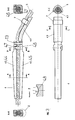
- Fig. 1 illustrates the wedge guy clamp according to the invention in two views and a separate sectional view B-B of the terminal body 1. Then there is the further developed wedge tension clamp from the parts clamp body 1, Pair of lugs 2, which is connected to the terminal body 1 via the pins 3, Rope holder 4 with inserted conductor rope 5 and holding element 6 in the version a C-shaped clamp 7.
- the sectional view B-B shows the structure of the two-part clamp body 1, consisting of the clamp body halves 1.1 and 1.2, which form the closed wedge chamber 1.3.
- the connection of the Terminal body halves 1.1, 1.2 are made by the nested Engagement elements 1.4.
- Fig. 2 shows the basic structure of the two-part clamp body with the clamp body halves 1.1 and 1.2.
- the U-shape of the clamp body halves 1.1, 1.2 with the resulting wedge chamber 1.3, which is free of undercut surfaces, can be clearly seen from the sectional views.
- These engagement elements are designed in pairs as latch 1.5 and pawl 1.6.
- the opening or perforation 3.1 for receiving the pin 3 can also be seen.
- the reliable coupling of the clamp body halves takes place via these engagement or locking elements 1.4.
- Fig. 3 illustrates the structure of the two-part cable holder 4.
- the upper illustration shows the side view of the cable holder 4 with the elongated cable receiving part 4.1 below, the shortened cable receiving part 4.2 above and the curved cable outlet 4.3.
- the rope receiving part 4.1 without the rope outlet 4.3 and the rope receiving part 4.2 form the wedge section of the rope receptacle, which consists of the upper wedge 4.4 and the lower wedge 4.5 and is inserted into the wedge chamber 1.3 of the wedge body 1, the contour of which is adapted to the wedge cross section.
- the conductor rope 5 is guided between the rope receiving parts 4.1 and 4.2 and lies on the rope outlet 4.3.
- the conductor rope 5 is locked at the rope outlet 4.3 by means of the clamp 7, see FIG. also the top view and sectional view in the lower view.
- the installation and locking of the upper and lower wedges 4.4, 4.5 with the inserted conductor rope 5 is carried out by means of the two hook-groove pairs 4.6, 4.7. Fixing of this cable receptacle 4 prepared for insertion into the clamp body 1 is carried out by the tensioning strap 13, which acts as a connecting element. A certain pretension can also be entered into the described assembly arrangement via this connection.
- the detail Z in connection with the section AA shows the inner contour of the upper and lower wedge 4.4, 4.5 and thus the shape of the cable duct 4.8. Then the curve of the cable channel 4.8 consists of a central part with the radius R and the tangents T adjoining on both sides.
- the C-shaped clamp 7 has at its leg ends 7.1 locking means 8 which engage in a locking counterpart 9 incorporated in the cable outlet 4.3.
- the clamps 7 can be installed without permanent deformation.
- Cross-sectional constrictions of this type ensure the necessary elasticity of assembly and thus facilitate assembly.
- the locking means 8 on the leg ends 7.1 can also be carried out in several locking stages.
- the adjustment to different rope diameters 5 takes place by means of a suitable insert 11 made of plastic, for example.
- This insert 11 also contributes to the cable-friendly storage and fixation of the cable 5 in the cable outlet 4.3.
- Another function of the insert 11 can be the stiffening of the C-shaped clamp 7 by filling in the cross-sectional constrictions 10.
- the locking counterpart 9 on the rope outlet 4.3 can also be in the longitudinal direction of the rope outlet 4.3 oblique or step-like in relation to the course of the imaginary center line of the Rope runout. This means that in the case of constant size C-shaped clamp 7 ropes 5 with different rope diameters tight on Rope run 4.3 held and braced.
- FIG. 5 is an embodiment of a two-part, annular Holding element 12, consisting of a C-shaped clamp upper part 12.1 and one Lower part of clamp 12.2. Both parts 12.1, 12.2 are by locking elements on their Leg ends 12.3 assembled into a closed ring.
- the closed, annular clamp 12 preferably consists of two extruded profiles with suitable locking elements on the leg ends 12.3, which are in one another grip and hold the conductor rope 5 in the rope outlet 4.3.
Landscapes
- Clamps And Clips (AREA)
- Suspension Of Electric Lines Or Cables (AREA)
- Electric Cable Installation (AREA)
- Electronic Switches (AREA)
- Vehicle Body Suspensions (AREA)
- Flanged Joints, Insulating Joints, And Other Joints (AREA)
Abstract
Description
Die Ausführung von Schmiedeteilen mit Hinterschneidungen bedingt höhere Fertigungsaufwendungen (Schmieden mit Schiebern) bzw. die zusätzliche mechanische Bearbeitung zum Herstellen der Hinterschneidungen mit damit verbundene höhere Werkzeugkosten.
Durch den Schmiedevorgang wird die gesamte Geometrie des Gehäuses im Keilkammer- und Verhakungsbereich mit hoher Maßgenauigkeit ausgeführt. Der Innenraum des Klemmenkörpers, also die Keilkammer weist erfindungsgemäß nur eine Keilform in Längs- bzw. Einschubrichtung auf. Diese Keilform hat die Kontur des Keilabschnitts des zweiteiligen Seilaufnahmeteils.
Diese Durchmesser-Toleranzen werden dadurch ausgeglichen, dass der Zapfen nach dem Einsetzen in die Lochung gestaucht und in einer auf der Innenseite des Klemmenkörpers vorhandenen Vertiefung vernietet wird. Der dabei durch das Stauchen im Durchmesser vergrößerte Zapfen gewährleistet eine zuverlässige, formschlüssige und mechanisch hoch belastbare Verbindung.
Die zweiteiligen Schellen bestehen aus zwei C-förmigen Elementen, dem Schellenoberteil und dem Schellenunterteil, die über an den jeweiligen Schenkelenden der Schellen befindliche Rast- oder Verriegelungselemente ineinander greifen und auf diese Weise eine geschlossene, das Leiterseil und das Seilaufnahmeteil umfassende Ringform bilden.
- Fig. 1
- eine Gesamtansicht der schraubenlosen Keilabspannklemme im Einbauzustand mit Schnittdarstellungen zum Klemmenkörperaufbau,
- Fig. 2
- eine Außen- und Schnittansicht zum Aufbau des Klemmenkörpers,
- Fig. 3
- die Darstellung der zweiteiligen Seilaufnahme in zwei Ansichten (Seitenansicht und Draufsicht) mit Halteelement,
- Fig. 4
- zwei Ausführungsformen des Halteelements, aufsitzend auf dem Seilauflauf,
- Fig. 5
- eine Ausführungsform eines zweiteiligen, ringförmigen Halteelements.
Aus den Schnittdarstellungen ist die U-form der Klemmenkörperhälften 1.1, 1.2 mit der sich daraus ergebenden Keilkammer 1.3, die frei ist von Hinterschneidungsflächen, deutlich zu erkennen.
An den Schenkeln der Klemmenkörperhälften 1.1, 1.2 sind - die Schenkelenden als Auflageflächen freihaltend - Stege 1.7 angeordnet, die als Eingriffselemente 1.4 ausgebildet sind. Diese Eingriffselemente sind paarweise als Falle 1.5 und Klinke 1.6 ausgeführt.
Zu erkennen ist auch die Öffnung bzw. Lochung 3.1 zur Aufnahme des Zapfens 3.
Über diese Eingriffs- bzw. Verriegelungselemente 1.4 erfolgt die zuverlässige Kopplung der Klemmenkörperhälften.
Das Seilaufnahmeteil 4.1 ohne den Seilauslauf 4.3 und das Seilaufnahmeteil 4.2 bilden den Keilabschnitt der Seilaufnahme, der aus dem Oberkeil 4.4 und dem Unterkeil 4.5 besteht und in den Klemmenkörper und zwar in die hinsichtlich ihrer Kontur dem Keilquerschnitt angepasste Keilkammer 1.3 des Klemmenkörpers 1 eingeschoben wird. Das Leiterseil 5 wird zwischen den Seilaufnahmeteilen 4.1 und 4.2 geführt und liegt auf dem Seilauslauf 4.3 auf. Die Arretierung des Leiterseils 5 am Seilauslauf 4.3 erfolgt mittels der Schelle 7, s. auch die Draufsicht und Schnittdarstellung in der unteren Ansicht.
Die Fixierung dieser zum Einschub in den Klemmenkörper 1 vorbereiteten Seilaufnahme 4 übernimmt das als Verbindungselement wirkende Spannband 13. Über diese Verbindung kann auch eine bestimmte Vorspannung in die beschriebene Montageanordnung eingetragen werden.
Aus der Einzelheit Z geht in Verbindung mit dem Schnitt A-A die Innenkontur von Ober- und Unterkeil 4.4, 4.5 und damit die Form des Seilkanals 4.8 hervor. Danach besteht der Kurvenzug des Seilkanals 4.8 aus einem Mittelteil mit dem Radius R und den sich beidseitig anschließenden Tangentialen T.
Dabei besitzt die C-förmige Schelle 7 an ihren Schenkelenden 7.1 Rastmittel 8, die in einen in den Seilauslauf 4.3 eingearbeiteten Rastgegenpart 9 eingreifen.
Mittels der Querschnittsverengungen 10 können die Schellen 7 ohne bleibende Verformung montiert werden.
Die Rastmittel 8 an den Schenkelenden 7.1 können auch in mehreren Raststufen ausgeführt werden.
Eine weitere Funktion der Einlage 11 kann die Versteifung der C-förmigen Schelle 7 durch Auffüllen der Querschnittsverengungen 10 sein.
- 1
- Klemmenkörper
1.1 Klemmenkörperhälfte
1.2 Klemmenkörperhälfte
1.3 Keilkammer
1.4 Eingriffselemente
1.5 Falle
1.6 Klinke
1.7 Steg - 2
- Laschenpaar
- 3
- Zapfen (am Klemmenkörper)
3.1 Öffnung zur Aufnahme des Zapfens 3 - 4
- Seilaufnahme
4.1 verlängertes Seilaufnahmeteil
4.2 verkürztes Seilaufnahmeteil
4.3 Verlängerung von 4.1, Seilauslauf
4.4 Oberkeil
4.5 Unterkeil
4.6 Haken
4.7 Nut
4.8 Seilkanal - 5
- Leiterseil
- 6
- Halteelement
- 7
- Schelle, Befestigungselement
7.1 Schenkelenden - 8
- Rastmittel an 7.1
- 9
- Rastgegenpart an 4.3
- 10
- Querschnittsverengungen
- 11
- Einlagen
- 12
- zweiteiliges Halteelement
12.1 Schellen-Oberteil
12.2 Schellen-Unterteil
12.3 Schenkelenden mit Rastelementen - 13
- Verbindungselement, Spannband
Claims (20)
- Schraubenlose Keilabspannklemme zum Abspannen von Aluminium-, Aldrey-, Aluminium-Stahl und Aldrey-Stahl-Seilen in Abspannketten für Mittel- und Hochspannungsfreileitungen bestehend ausa) einem zweiteiligen längsgeteilten Klemmenkörper (1), dessen Keilkammer (1.3) aus den mit den spiegelsymmetrisch mit den Seitenschenkelenden ihres U-Profil-Querschnitts aufeinander stehenden beiden Klemmenkörperhälften (1.1, 1.2) gleicher Geometrie gebildet wird, wobei die Keilkammer (1.3) keine Hinterschneidungsflächen aufweist und in Längs- und damit Einschubrichtung eine Keilform besitzt und zur Verbindung der Klemmenkörperhälften (1.1, 1.2) an den Enden der U-förmigen Seitenschenkel mindestens ein nach außen abstehendes Paar von Eingriffselementen (1.4) vorhanden ist, und der Klemmenkörper (1) mit einem Laschenpaar (2) mittels zweier Zapfen (3) verbunden ist,b) einer zweiteiligen Seilaufnahme (4) mit im Keilabschnitt an die Kontur der Keilkammer (1.3) angepasster Keilform, die das Leiterseil (5) umschließend in den Klemmenkörper (1) eingeschoben wird, wobei eines der beiden Seilaufnahmeteile (4) verlängert und im Seilauslauf gebogen ausgeführt ist und das Leiterseil im Bereich des Seilauslaufs (4.3) auf dem verlängerten Seilaufnahmeteil (4.1) aufliegend oder anliegend schraubenlos mittels eines Halteelements (6) arretiert ist.
- Keilabspannklemme nach Anspruch 1,
dadurch gekennzeichnet, dass der Klemmenkörper (1) und/oder die Seilaufnahmeteile (4.1, 4.2) als Schmiedeteil aus einer Aluminium-Knetlegierung ausgeführt ist. - Keilabspannklemme nach Anspruch 1 oder 2,
dadurch gekennzeichnet, dass die Klemmenkörperhälften (1.1, 1.2) mittels mindestens eines Verbindungselementes, das eine scharnierartige einseitige Kopplung der Klemmenkörperhälften bewirkt, unverlierbar miteinander verbunden sind. - Keilabspannklemme nach einem der Ansprüche 1 bis 3,
dadurch gekennzeichnet, dass die Eingriffselemente (1.4) als Falle (1.5) und in diese Falle einschiebbare Klinke (1.6) ausgeführt sind, wobei die Falle (1.5) in einen Steg (1.7) eingebracht ist, der sich nach außen abgekröpft in Verlängerung des einen U-Schenkels der Klemmenkörperhälften (1.1, 1.2) erstreckt und die Klinke (1.6) rechtwinklig vom jeweils anderen U-Schenkelende der Klemmenkörperhälften nach außen absteht und die Öffnung der Falle (1.5) die Abmessungen des Klinkenquerschnitts aufweist, und wobei Falle (1.5) und Klinke (1.6) so angeordnet sind, dass die Stirnseiten der U-Schenkel als Auflagefläche der beiden Klemmenkörperhälften zur Bildung der Keilkammer (1.3) frei bleiben. - Keilabspannklemme nach einem der Ansprüche 1 bis 4,
dadurch gekennzeichnet, dass bei der Ausführung von Zapfen (3) und Klemmenkörper (1) als Alu-Schmiedeteile die Aufnahmebohrung (3.1) für den Zapfen (3) als mit groben Toleranzen behaftete Lochung ausgeführt ist und der durch die Lochung geführte Zapfen (3) auf den Lochungsdurchmesser gestaucht und in einer auf der Innenseite des Klemmenkörpers (1) vorhandenen Vertiefung vernietet ist. - Keilabspannklemme nach einem der Ansprüche 1 bis 5,
dadurch gekennzeichnet, dass zur Positionierung und Verriegelung von Oberkeil (4.4) und Unterkeil (4.5) der zweiteiligen Seilaufnahme (4) in der Montageposition bei zwischen Ober- und Unterkeil eingelegten Leiterseil (5) vor dem Einschieben der Keilverbindung in die Keilkammer (1.3) mindestens eine Haken (4.6)-Nut-(4.7)Paarung in Ober- und Unterkeil (4.4, 4.5) vorhanden ist. - Keilabspannklemme nach einem der Ansprüche 1 bis 6,
dadurch gekennzeichnet, dass zur Herstellung einer Verbindung der beiden Teile der Seilaufnahme (4) und damit zur Gewährleistung sowohl der Unverlierbarkeit der beiden Seilaufnahmeteile (4.1, 4.2) als auch zur Fixierung der Seilaufnahme auf dem Leiterseil (5) ein mit beiden Seilaufnahmeteilen (4.1, 4.2) verbundenes, von außen angreifendes Verbindungselement (13) in Form eines Spannbandes, einer Schlauchschelle oder dgl., mit oder ohne Nutführung, vorgesehen ist, das bei der Montage ein bestimmte Vorspannkraft auf die Montageanordnung Ober- und Unterkeil (4.4, 4.5) plus eingeschlossenes Leiterseil (5) ausüben kann. - Keilabspannklemme nach einem der Ansprüche 1 bis 7,
dadurch gekennzeichnet, dass der von den Innenseiten des Ober- und Unterkeils (4.4, 4.5) gebildete Seilkanal (4.8) sich in seiner Querschnittskontur zusammensetzt aus einem Mittelteil mit dem Radius R und beidseitig sich anschließenden Tangentialflächen T, (s. Einzelheit Z in Fig. 3). - Keilabspannklemme nach Anspruch 8,
dadurch gekennzeichnet, dass der Radius R in seiner Größe mindestens dem Radius des aufliegenden Leiterseiles (5) entspricht. - Keilabspannklemme nach einem der Ansprüche 1 bis 9,
dadurch gekennzeichnet, dass das verlängerte Seilaufnahmeteil (4.1) mit dem Seilauslauf (4.3) im Verbund der beiden Teile (4.1, 4.2) der Seilaufnahme (4) unten oder oben liegend als Gegenpart zum zweiten Seilaufnahmeteil (4.2) im Klemmenkörper (1) angeordnet ist. - Keilabspannklemme nach Anspruch 10,
dadurch gekennzeichnet, dass auf dem Seilauslauf (4.3) eine geeignete Profilierung in Form von Nasen und/oder Vertiefungen eingebracht ist. - Keilabspannklemme nach einem der Ansprüche 1 bis 11,
dadurch gekennzeichnet, dass als Halteelement (6) zur Arretierung des Leiterseils (5) auf der gebogenen Verlängerung (4.3) des Seilaufnahmeteils (4.1) mindestens eine C-förmige Schelle (7) vorgesehen ist. - Keilabspannklemme nach Anspruch 12,
dadurch gekennzeichnet, dass die C-förmige Schelle (7) aus einem Strangpressprofil oder einem gebogenen Federmaterial besteht. - Keilabspannklemme nach Anspruch 12 oder 13,
dadurch gekennzeichnet, dass die Schenkelenden der Schelle (7) Rastmittel (8) aufweisen, die in einen Rastgegenpart (9) eingreifen, der in die Seitenzonen der Verlängerung (4.3) des Seilaufnahmeteils (4.1) eingearbeitet oder im Bereich der Seitenzonen vorhanden ist. - Keilabspannklemme nach Anspruch 14,
dadurch gekennzeichnet, dass der Rastgegenpart (9) längs des verlängerten Seilaufnahmeteils (4.1) schräg oder stufenförmig am Seilauslauf (4.3) ausgeführt ist. - Keilabspannklemme nach einem der Ansprüche 1 bis 15,
dadurch gekennzeichnet, dass die C-förmige Schelle (7) mit der Verlängerung (4.3) des Seilaufnahmeteils (4.1) unverlierbar verbunden ist und durch Drehen und/oder Verschieben auf der Verlängerung (4.3) in die Halteposition für das Leiterseil (5) gebracht wird. - Keilabspannklemme nach einem der Ansprüche 12 bis 16,
dadurch gekennzeichnet, dass die C-förmige Schelle (7) Gelenke in Form von Querschnittsverengungen (10) aufweist. - Keilabspannklemme nach einem der Ansprüche 12 bis 17,
dadurch gekennzeichnet, dass insbesondere zur Anpassung an verschiedene Seildurchmesser die C-förmige Schelle (7) geeignete Einlagen (11) aufweist. - Keilabspannklemme nach Anspruch 18,
dadurch gekennzeichnet, dass die Einlagen (11) elastisch und aus Kunststoff und dgl. ausgeführt sind. - Keilabspannklemme nach einem der Ansprüche 1 bis 19,
dadurch gekennzeichnet, dass als Halteelement (6) eine zweiteilige, sich nach der Montage zu einem geschlossenen Ring ergänzende Schelle (12) vorgesehen ist, die aus einem C-förmigen Schellenoberteil (12.1) und einem C-förmigen Schellenunterteil (12.2) besteht, wobei die ringförmige Verbindung der beiden Schellenteile (12.1, 12.2) durch in den einander zugekehrten Schenkelenden (12.3) befindliche Rast- und Verriegelungselemente erfolgt.
Priority Applications (7)
| Application Number | Priority Date | Filing Date | Title |
|---|---|---|---|
| EP01110907A EP1255339B1 (de) | 2001-05-05 | 2001-05-05 | Schraubenlose Keilspannklemme |
| DE50111195T DE50111195D1 (de) | 2001-05-05 | 2001-05-05 | Schraubenlose Keilspannklemme |
| ES01110907T ES2274835T3 (es) | 2001-05-05 | 2001-05-05 | Pinza de acuñamiento y anclaje sin tornillos. |
| AT01110907T ATE342601T1 (de) | 2001-05-05 | 2001-05-05 | Schraubenlose keilspannklemme |
| HR20020371A HRP20020371A2 (en) | 2001-05-05 | 2002-04-26 | Boltless wedge clamp |
| PL02353691A PL353691A1 (en) | 2001-05-05 | 2002-04-30 | Screw-less pull-off clamp |
| SK623-2002A SK284466B6 (sk) | 2001-05-05 | 2002-05-03 | Bezskrutková klinová upínacia svorka |
Applications Claiming Priority (1)
| Application Number | Priority Date | Filing Date | Title |
|---|---|---|---|
| EP01110907A EP1255339B1 (de) | 2001-05-05 | 2001-05-05 | Schraubenlose Keilspannklemme |
Publications (2)
| Publication Number | Publication Date |
|---|---|
| EP1255339A1 true EP1255339A1 (de) | 2002-11-06 |
| EP1255339B1 EP1255339B1 (de) | 2006-10-11 |
Family
ID=8177331
Family Applications (1)
| Application Number | Title | Priority Date | Filing Date |
|---|---|---|---|
| EP01110907A Expired - Lifetime EP1255339B1 (de) | 2001-05-05 | 2001-05-05 | Schraubenlose Keilspannklemme |
Country Status (7)
| Country | Link |
|---|---|
| EP (1) | EP1255339B1 (de) |
| AT (1) | ATE342601T1 (de) |
| DE (1) | DE50111195D1 (de) |
| ES (1) | ES2274835T3 (de) |
| HR (1) | HRP20020371A2 (de) |
| PL (1) | PL353691A1 (de) |
| SK (1) | SK284466B6 (de) |
Cited By (3)
| Publication number | Priority date | Publication date | Assignee | Title |
|---|---|---|---|---|
| IT201800007099A1 (it) * | 2018-07-11 | 2020-01-11 | Morsetto di amarro a cuneo per linee elettriche | |
| CN111853042A (zh) * | 2020-06-08 | 2020-10-30 | 湖北省丹江口丹传汽车传动轴有限公司 | 一种复合结构的铝合金传动轴总成及其生产方法 |
| CN120709900A (zh) * | 2025-07-11 | 2025-09-26 | 自贡市大西南电力器材制造有限公司 | 一种液压型耐张线夹连接金具 |
Families Citing this family (3)
| Publication number | Priority date | Publication date | Assignee | Title |
|---|---|---|---|---|
| US10161194B2 (en) | 2013-11-11 | 2018-12-25 | Halliburton Energy Services, Inc. | Connector for a downhole conveyance |
| RU198249U1 (ru) * | 2020-02-12 | 2020-06-26 | Общество С Ограниченной Ответственностью "Мзва" (Ооо "Мзва") | Анкерный зажим |
| DE102023201106A1 (de) | 2023-02-10 | 2024-08-14 | Richard Bergner Holding GmbH & Co. KG | Keilabspannklemme sowie Abspannvorrichtung mit einer solchen Keilabspannklemme |
Citations (4)
| Publication number | Priority date | Publication date | Assignee | Title |
|---|---|---|---|---|
| EP0132208A1 (de) * | 1983-06-15 | 1985-01-23 | MALICO : Société Anonyme | Abspannklemme für isolierte Tragseile mit mehreren Leitern |
| FR2647878A1 (fr) * | 1989-05-31 | 1990-12-07 | Capelles De La Fuente Rosa | Pince d'attache perfectionnee pour cables aeriens, en particulier electriques |
| DE4019999A1 (de) * | 1990-06-22 | 1992-01-02 | Preformed Line Products Great | Keilabspannklemme fuer elektrische leiter |
| EP0486375A1 (de) * | 1990-11-12 | 1992-05-20 | Etablissements Derancourt | Verankerungsvorrichtung für elektrische Litzenleitung |
-
2001
- 2001-05-05 DE DE50111195T patent/DE50111195D1/de not_active Expired - Lifetime
- 2001-05-05 AT AT01110907T patent/ATE342601T1/de active
- 2001-05-05 EP EP01110907A patent/EP1255339B1/de not_active Expired - Lifetime
- 2001-05-05 ES ES01110907T patent/ES2274835T3/es not_active Expired - Lifetime
-
2002
- 2002-04-26 HR HR20020371A patent/HRP20020371A2/hr not_active Application Discontinuation
- 2002-04-30 PL PL02353691A patent/PL353691A1/xx not_active Application Discontinuation
- 2002-05-03 SK SK623-2002A patent/SK284466B6/sk not_active IP Right Cessation
Patent Citations (4)
| Publication number | Priority date | Publication date | Assignee | Title |
|---|---|---|---|---|
| EP0132208A1 (de) * | 1983-06-15 | 1985-01-23 | MALICO : Société Anonyme | Abspannklemme für isolierte Tragseile mit mehreren Leitern |
| FR2647878A1 (fr) * | 1989-05-31 | 1990-12-07 | Capelles De La Fuente Rosa | Pince d'attache perfectionnee pour cables aeriens, en particulier electriques |
| DE4019999A1 (de) * | 1990-06-22 | 1992-01-02 | Preformed Line Products Great | Keilabspannklemme fuer elektrische leiter |
| EP0486375A1 (de) * | 1990-11-12 | 1992-05-20 | Etablissements Derancourt | Verankerungsvorrichtung für elektrische Litzenleitung |
Cited By (5)
| Publication number | Priority date | Publication date | Assignee | Title |
|---|---|---|---|---|
| IT201800007099A1 (it) * | 2018-07-11 | 2020-01-11 | Morsetto di amarro a cuneo per linee elettriche | |
| EP3595108A1 (de) | 2018-07-11 | 2020-01-15 | A. Salvi & C. S.R.L. | Keilspannklemme zum spannen von leiterseile |
| CN111853042A (zh) * | 2020-06-08 | 2020-10-30 | 湖北省丹江口丹传汽车传动轴有限公司 | 一种复合结构的铝合金传动轴总成及其生产方法 |
| CN111853042B (zh) * | 2020-06-08 | 2021-02-19 | 湖北省丹江口丹传汽车传动轴有限公司 | 一种复合结构的铝合金传动轴总成及其生产方法 |
| CN120709900A (zh) * | 2025-07-11 | 2025-09-26 | 自贡市大西南电力器材制造有限公司 | 一种液压型耐张线夹连接金具 |
Also Published As
| Publication number | Publication date |
|---|---|
| SK284466B6 (sk) | 2005-04-01 |
| PL353691A1 (en) | 2002-11-18 |
| EP1255339B1 (de) | 2006-10-11 |
| ATE342601T1 (de) | 2006-11-15 |
| DE50111195D1 (de) | 2006-11-23 |
| SK6232002A3 (en) | 2002-11-06 |
| HRP20020371A2 (en) | 2002-12-31 |
| ES2274835T3 (es) | 2007-06-01 |
Similar Documents
| Publication | Publication Date | Title |
|---|---|---|
| DE69615824T2 (de) | Klemme mit schlangenförmigen klemmstück | |
| EP2248946B1 (de) | Verbindungselement für Laufschienen | |
| DE2647235C2 (de) | Distanzhalter für durch Schutzrohre hindurchgeführte Rohre | |
| DE69428479T2 (de) | Adapter für die Verbindung von faseroptischen Steckern oder dergleichen | |
| EP3254340B1 (de) | Halterahmen für steckverbindermodule | |
| EP2776737B1 (de) | Gurt oder gurtselement mit offenem ende und befestigungsvorrichtung dafür | |
| DE3817472A1 (de) | Verriegelung fuer eine fluidische steckverbindung | |
| EP3835638A1 (de) | Vorrichtung zur befestigung von leitungen | |
| DE202006007821U1 (de) | Spann- oder Führungsschiene mit Verliersicherung für Haltebolzen | |
| DE19526248C2 (de) | Steckverbinder | |
| EP1255339B1 (de) | Schraubenlose Keilspannklemme | |
| DE202019100877U1 (de) | Endbefestigungsteil für eine Energieführungskette | |
| DE102004018492B3 (de) | Steckbuchse zum elektrisch leitenden Verbinden mit einem Steckstift, insbesondere Flachsteckstift | |
| DE102004002921A1 (de) | Bandförmiges Kontaktelement, Verfahren zu seiner Herstellung, sowie Anwendung eines solchen Kontaktelements | |
| DE69303229T2 (de) | Halterung für mehrere Leitungen, Kabel oder ähnliches | |
| DE102010053357A1 (de) | Rohrschelle | |
| DE202004013160U1 (de) | Hochstromschnittstelle für Kraftfahrzeuge | |
| DE3623399C1 (en) | Totally insulated anchor clamp (tension clamp, dead-end clamp) | |
| DE29719650U1 (de) | Schiebeklemme | |
| WO2004040708A1 (de) | Flex-bus-steckverbinder | |
| DE102008007135A1 (de) | Befestigungselement | |
| EP1462310B1 (de) | Lenksäulenmodul | |
| DE10228137B4 (de) | Fixiereinrichtung sowie Schraubverbinder für Kabelleiter mit einer derartigen Fixiereinrichtung | |
| DE102004008715B4 (de) | Stecker | |
| DE3108641A1 (de) | Keil-abspannklemme fuer elektrische leiter |
Legal Events
| Date | Code | Title | Description |
|---|---|---|---|
| PUAI | Public reference made under article 153(3) epc to a published international application that has entered the european phase |
Free format text: ORIGINAL CODE: 0009012 |
|
| AK | Designated contracting states |
Kind code of ref document: A1 Designated state(s): AT BE CH CY DE DK ES FI FR GB GR IE IT LI LU MC NL PT SE TR |
|
| AX | Request for extension of the european patent |
Free format text: AL;LT;LV;MK;RO;SI |
|
| 17P | Request for examination filed |
Effective date: 20030129 |
|
| AKX | Designation fees paid |
Designated state(s): AT DE ES GB IT |
|
| GRAP | Despatch of communication of intention to grant a patent |
Free format text: ORIGINAL CODE: EPIDOSNIGR1 |
|
| GRAS | Grant fee paid |
Free format text: ORIGINAL CODE: EPIDOSNIGR3 |
|
| GRAA | (expected) grant |
Free format text: ORIGINAL CODE: 0009210 |
|
| AK | Designated contracting states |
Kind code of ref document: B1 Designated state(s): AT DE ES GB IT |
|
| REG | Reference to a national code |
Ref country code: GB Ref legal event code: FG4D Free format text: NOT ENGLISH |
|
| REF | Corresponds to: |
Ref document number: 50111195 Country of ref document: DE Date of ref document: 20061123 Kind code of ref document: P |
|
| GBT | Gb: translation of ep patent filed (gb section 77(6)(a)/1977) |
Effective date: 20070117 |
|
| PGFP | Annual fee paid to national office [announced via postgrant information from national office to epo] |
Ref country code: ES Payment date: 20070525 Year of fee payment: 7 |
|
| REG | Reference to a national code |
Ref country code: ES Ref legal event code: FG2A Ref document number: 2274835 Country of ref document: ES Kind code of ref document: T3 |
|
| PLBE | No opposition filed within time limit |
Free format text: ORIGINAL CODE: 0009261 |
|
| STAA | Information on the status of an ep patent application or granted ep patent |
Free format text: STATUS: NO OPPOSITION FILED WITHIN TIME LIMIT |
|
| 26N | No opposition filed |
Effective date: 20070712 |
|
| PGFP | Annual fee paid to national office [announced via postgrant information from national office to epo] |
Ref country code: IT Payment date: 20070526 Year of fee payment: 7 |
|
| REG | Reference to a national code |
Ref country code: ES Ref legal event code: FD2A Effective date: 20080506 |
|
| PG25 | Lapsed in a contracting state [announced via postgrant information from national office to epo] |
Ref country code: IT Free format text: LAPSE BECAUSE OF NON-PAYMENT OF DUE FEES Effective date: 20080505 |
|
| PG25 | Lapsed in a contracting state [announced via postgrant information from national office to epo] |
Ref country code: ES Free format text: LAPSE BECAUSE OF NON-PAYMENT OF DUE FEES Effective date: 20080506 |
|
| PGFP | Annual fee paid to national office [announced via postgrant information from national office to epo] |
Ref country code: AT Payment date: 20120521 Year of fee payment: 12 |
|
| PGFP | Annual fee paid to national office [announced via postgrant information from national office to epo] |
Ref country code: GB Payment date: 20130522 Year of fee payment: 13 Ref country code: DE Payment date: 20130315 Year of fee payment: 13 |
|
| REG | Reference to a national code |
Ref country code: DE Ref legal event code: R119 Ref document number: 50111195 Country of ref document: DE |
|
| REG | Reference to a national code |
Ref country code: AT Ref legal event code: MM01 Ref document number: 342601 Country of ref document: AT Kind code of ref document: T Effective date: 20140505 |
|
| GBPC | Gb: european patent ceased through non-payment of renewal fee |
Effective date: 20140505 |
|
| PG25 | Lapsed in a contracting state [announced via postgrant information from national office to epo] |
Ref country code: AT Free format text: LAPSE BECAUSE OF NON-PAYMENT OF DUE FEES Effective date: 20140505 |
|
| REG | Reference to a national code |
Ref country code: DE Ref legal event code: R119 Ref document number: 50111195 Country of ref document: DE Effective date: 20141202 |
|
| PG25 | Lapsed in a contracting state [announced via postgrant information from national office to epo] |
Ref country code: DE Free format text: LAPSE BECAUSE OF NON-PAYMENT OF DUE FEES Effective date: 20141202 |
|
| PG25 | Lapsed in a contracting state [announced via postgrant information from national office to epo] |
Ref country code: GB Free format text: LAPSE BECAUSE OF NON-PAYMENT OF DUE FEES Effective date: 20140505 |