EP1255014A1 - Sliding door arrangement for vehicle - Google Patents
Sliding door arrangement for vehicle Download PDFInfo
- Publication number
- EP1255014A1 EP1255014A1 EP02290764A EP02290764A EP1255014A1 EP 1255014 A1 EP1255014 A1 EP 1255014A1 EP 02290764 A EP02290764 A EP 02290764A EP 02290764 A EP02290764 A EP 02290764A EP 1255014 A1 EP1255014 A1 EP 1255014A1
- Authority
- EP
- European Patent Office
- Prior art keywords
- door
- rail
- arm
- holding
- sliding
- Prior art date
- Legal status (The legal status is an assumption and is not a legal conclusion. Google has not performed a legal analysis and makes no representation as to the accuracy of the status listed.)
- Granted
Links
Images


Classifications
-
- E—FIXED CONSTRUCTIONS
- E05—LOCKS; KEYS; WINDOW OR DOOR FITTINGS; SAFES
- E05D—HINGES OR SUSPENSION DEVICES FOR DOORS, WINDOWS OR WINGS
- E05D15/00—Suspension arrangements for wings
- E05D15/06—Suspension arrangements for wings for wings sliding horizontally more or less in their own plane
- E05D15/10—Suspension arrangements for wings for wings sliding horizontally more or less in their own plane movable out of one plane into a second parallel plane
- E05D15/1065—Suspension arrangements for wings for wings sliding horizontally more or less in their own plane movable out of one plane into a second parallel plane with transversely moving track
- E05D15/1081—Suspension arrangements for wings for wings sliding horizontally more or less in their own plane movable out of one plane into a second parallel plane with transversely moving track specially adapted for vehicles
-
- E—FIXED CONSTRUCTIONS
- E05—LOCKS; KEYS; WINDOW OR DOOR FITTINGS; SAFES
- E05D—HINGES OR SUSPENSION DEVICES FOR DOORS, WINDOWS OR WINGS
- E05D15/00—Suspension arrangements for wings
- E05D15/06—Suspension arrangements for wings for wings sliding horizontally more or less in their own plane
- E05D15/10—Suspension arrangements for wings for wings sliding horizontally more or less in their own plane movable out of one plane into a second parallel plane
- E05D15/1005—Suspension arrangements for wings for wings sliding horizontally more or less in their own plane movable out of one plane into a second parallel plane the wing being supported on arms movable in horizontal planes
- E05D15/101—Suspension arrangements for wings for wings sliding horizontally more or less in their own plane movable out of one plane into a second parallel plane the wing being supported on arms movable in horizontal planes specially adapted for vehicles
-
- E—FIXED CONSTRUCTIONS
- E05—LOCKS; KEYS; WINDOW OR DOOR FITTINGS; SAFES
- E05D—HINGES OR SUSPENSION DEVICES FOR DOORS, WINDOWS OR WINGS
- E05D15/00—Suspension arrangements for wings
- E05D15/06—Suspension arrangements for wings for wings sliding horizontally more or less in their own plane
- E05D15/10—Suspension arrangements for wings for wings sliding horizontally more or less in their own plane movable out of one plane into a second parallel plane
- E05D15/1065—Suspension arrangements for wings for wings sliding horizontally more or less in their own plane movable out of one plane into a second parallel plane with transversely moving track
- E05D2015/1084—Suspension arrangements for wings for wings sliding horizontally more or less in their own plane movable out of one plane into a second parallel plane with transversely moving track the carriage being directly linked to the fixed frame, e.g. slidingly
- E05D2015/1086—Suspension arrangements for wings for wings sliding horizontally more or less in their own plane movable out of one plane into a second parallel plane with transversely moving track the carriage being directly linked to the fixed frame, e.g. slidingly swingingly, e.g. on arms
- E05D2015/1089—Suspension arrangements for wings for wings sliding horizontally more or less in their own plane movable out of one plane into a second parallel plane with transversely moving track the carriage being directly linked to the fixed frame, e.g. slidingly swingingly, e.g. on arms the carriage having means for preventing rotation of the wing
-
- E—FIXED CONSTRUCTIONS
- E05—LOCKS; KEYS; WINDOW OR DOOR FITTINGS; SAFES
- E05D—HINGES OR SUSPENSION DEVICES FOR DOORS, WINDOWS OR WINGS
- E05D15/00—Suspension arrangements for wings
- E05D15/06—Suspension arrangements for wings for wings sliding horizontally more or less in their own plane
- E05D15/10—Suspension arrangements for wings for wings sliding horizontally more or less in their own plane movable out of one plane into a second parallel plane
- E05D15/1065—Suspension arrangements for wings for wings sliding horizontally more or less in their own plane movable out of one plane into a second parallel plane with transversely moving track
- E05D2015/1084—Suspension arrangements for wings for wings sliding horizontally more or less in their own plane movable out of one plane into a second parallel plane with transversely moving track the carriage being directly linked to the fixed frame, e.g. slidingly
- E05D2015/1086—Suspension arrangements for wings for wings sliding horizontally more or less in their own plane movable out of one plane into a second parallel plane with transversely moving track the carriage being directly linked to the fixed frame, e.g. slidingly swingingly, e.g. on arms
- E05D2015/1092—Suspension arrangements for wings for wings sliding horizontally more or less in their own plane movable out of one plane into a second parallel plane with transversely moving track the carriage being directly linked to the fixed frame, e.g. slidingly swingingly, e.g. on arms the carriage swinging or rotating in curved track sections
-
- E—FIXED CONSTRUCTIONS
- E05—LOCKS; KEYS; WINDOW OR DOOR FITTINGS; SAFES
- E05Y—INDEXING SCHEME RELATING TO HINGES OR OTHER SUSPENSION DEVICES FOR DOORS, WINDOWS OR WINGS AND DEVICES FOR MOVING WINGS INTO OPEN OR CLOSED POSITION, CHECKS FOR WINGS AND WING FITTINGS NOT OTHERWISE PROVIDED FOR, CONCERNED WITH THE FUNCTIONING OF THE WING
- E05Y2900/00—Application of doors, windows, wings or fittings thereof
- E05Y2900/50—Application of doors, windows, wings or fittings thereof for vehicles
- E05Y2900/53—Application of doors, windows, wings or fittings thereof for vehicles characterised by the type of wing
- E05Y2900/531—Doors
Definitions
- the invention relates to an arrangement of a door sliding of a motor vehicle.
- the invention relates more particularly to an arrangement a sliding door of a motor vehicle comprising means for holding and guiding the door between a open position and a closed position relative to the vehicle structure.
- Document FR1577398 describes a door arrangement sliding system comprising two arms articulated on the door located respectively at the front and back of the door and sliding in two respectively rails located on the structure, as well as two arms articulated on the structure and sliding respectively in two rails located on the door.
- the two door rails are located respectively in the lower part and halfway up the door.
- the two rails of the structure are located respectively substantially in the lower part and halfway up the door.
- An object of the present invention is to provide a arrangement of a sliding door for a motor vehicle overcoming all or part of the disadvantages of the prior art noted above.
- the device according to the invention is essentially characterized in that the holding and guiding means consist of three arms cooperating respectively with three guide rails, the holding and guiding means being dimensioned and arranged relatively so that the ends of the arms sliding in the rails form the vertices of a triangle doorstop fictitious as well when the door is in closed position only when in the open position.
- the sliding door 1 shown in Figures 1 to 3 is maintained and guided by means of three cooperating arms 3, 5, 7 sliding with, respectively, three rails 4, 6, 8 of guide.
- a first arm 3 has one end secured to the part lower front of door 1 and another end B which slides in a first lower rail 4 secured to the structure 2 of the vehicle.
- the sliding end B of the first arm 3 includes, for example, a rotating roller system around a axis substantially parallel to the plane of door 1.
- the first rail 4 is bent inward from the vehicle towards the front of the vehicle, to participate during the dislocation and nesting phases of door 1 by relation to structure 2.
- a second arm 5 has an end articulated on the structure 2 and the other end C guided by sliding in a second lower rail 6 secured to door 1.
- the second rail 6 is located substantially near the bottom edge of the door 1.
- the end C of the arm guided in the second rail 6 also includes a rolling roller system described more in detail below.
- the third arm 7 has one end articulated on the rear part of door 1 and the other end guided in sliding in a third integral intermediate rail 8 of structure 2.
- the third rail 8 is located approximately halfway up door 1, behind the opening 13 provided for the door in the structure 2.
- the arms 3, 5, 7 for holding the door as well as the guide rails 4, 6, 8 of the latter are dimensioned and arranged relatively so that the ends B, C, A of arms 3, 5, 7 sliding in the rails 4, 6, 8 form the vertices of a fictitious triangle ABC as well when door 1 is in the closed position (figure 1 and 2) than when in the open position (1 and 3).
- the triangle ABC defined by the points of maintenance of the door 1 is preferably located in a plane substantially parallel to the plane of the door.
- such an arrangement according to the invention allows easy operation of the door by a user while having simplified holding and guiding means compared to the prior art.
- the arms 3, 5, 7 for holding the door as well as the guide rails 4, 6, 8 of the latter are sized and arranged relatively so that the distance L separating the sliding ends B, C from first 3 and second 5 arms continuously remains greater than a minimum distance of around 150 to 300mm approximately.
- the distance L separating the sliding ends B, C of the first 3 and second 5 arms is between 150 to 300mm approximately when door 1 is in the open position ( Figures 1 and 3)
- This arrangement of the holding and guiding means provides perfect operation and maintenance of the door during its use.
- the end sliding C of the second arm 5 has a system with three rollers 10, 11, 12 rotary.
- the three rollers 10, 11, 12 are relatively arranged so that their axes of rotation respective 110, 111, 112 form, in projection in a plane substantially perpendicular to the plane of door 1, the vertices of a fixed triangle.
- first rollers 10, 11 roll respectively against the two opposite faces of the same vertical flank of the second rail 6.
- the third roller 12 is, as to him, offset from the first two rollers 10, 11 towards rear of rail 6.
- the third roller 12 is arranged so as to roll substantially on the same side of rail 6 as one 10 of the two first rollers 10, 11 when the door slides.
- the third roller 12 is preferably located in a different plane from the other two rollers 10, 11.
- the third roller 12 is located in below the horizontal plane containing the other two rollers 10, 11.
- the rear end of the second rail 6 has a portion 9 folded towards the door 1 which forms a stop for the first two rollers 10, 11. That is to say, when the end C of the second arm 5 arrives at the end of the race at the rear end of the second rail 6, the third roller 12 leaves rail 6 and allows the second arm 5 to disengage or to nest door 1 relative to structure 2.
- Figure 4 illustrates three different positions ⁇ , ⁇ and ⁇ of the rear end of the rail 6 or during the operation of the door 1. To better illustrate the different positions of the second rail 6, the latter's reference number has been supplemented by the letter ⁇ , ⁇ or ⁇ corresponding to its position.
- a first position ⁇ door open
- the rail 6 ⁇ is placed between on the one hand a roller 11 said interior and the two other rollers 10, 12 said to be external.
- the user begins to close door 1, it slides towards the front of the vehicle.
- the second rail 6 then slides also towards the front between the inner 11 and outer 10, 12 rollers (direction T, figure 4).
- the maximum opening position of door 1 is defined, for example, by one or more stops formed at the level guide rails 4, 6, 8.
- a stop limiting the opening is formed at the rear end of the first lower rail 4 secured to structure 2 and / or to the front end of the second rail 6.
Abstract
Description
L'invention se rapporte à un agencement d'une porte coulissante de véhicule automobile.The invention relates to an arrangement of a door sliding of a motor vehicle.
L'invention concerne plus particulièrement un agencement d'une porte coulissante de véhicule automobile comportant des moyens de maintien et de guidage de la porte entre une position ouverte et une position fermée par rapport à la structure du véhicule.The invention relates more particularly to an arrangement a sliding door of a motor vehicle comprising means for holding and guiding the door between a open position and a closed position relative to the vehicle structure.
Le document FR1577398 décrit un agencement de porte coulissante de véhicule comportant deux bras articulés sur la porte situés respectivement au niveau des parties avant et arrière de la porte et coulissant respectivement dans deux rails situés sur la structure, ainsi que deux bras articulés sur la structure et coulissant respectivement dans deux rails situés sur la porte. Les deux rails sur porte sont situés respectivement en partie basse et à mi-hauteur de la porte. Les deux rails de la structure sont situés respectivement sensiblement en partie basse et à mi-hauteur de la porte.Document FR1577398 describes a door arrangement sliding system comprising two arms articulated on the door located respectively at the front and back of the door and sliding in two respectively rails located on the structure, as well as two arms articulated on the structure and sliding respectively in two rails located on the door. The two door rails are located respectively in the lower part and halfway up the door. The two rails of the structure are located respectively substantially in the lower part and halfway up the door.
Un tel agencement permet de manoeuvrer et de maintenir la porte lors de ses déplacements cependant, il présente une structure complexe et coûteuse, en raison notamment au grand nombre d'éléments nécessaires au maintien et au guidage de la porte.Such an arrangement makes it possible to maneuver and maintain the door when moving, however, it presents a complex and expensive structure, due in particular to the large number of elements necessary to maintain and guide the door.
Un but de la présente invention est de proposer un agencement d'une porte coulissante de véhicule automobile palliant tout ou partie des inconvénients de l'art antérieur relevés ci-dessus.An object of the present invention is to provide a arrangement of a sliding door for a motor vehicle overcoming all or part of the disadvantages of the prior art noted above.
A cette fin, le dispositif selon l'invention, par ailleurs conforme à la définition générique qu'en donne le préambule ci-dessus, est essentiellement caractérisé en ce que les moyens de maintien et de guidage sont constitués de trois bras coopérant respectivement avec trois rails de guidage, les moyens de maintien et de guidage étant dimensionnés et disposés relativement de façon que les extrémités des bras coulissant dans les rails forment les sommets d'un triangle fictif de maintien de la porte aussi bien lorsque la porte est en position fermée que lorsqu'elle est en position ouverte.To this end, the device according to the invention, moreover conforms to the generic definition given in the preamble above, is essentially characterized in that the holding and guiding means consist of three arms cooperating respectively with three guide rails, the holding and guiding means being dimensioned and arranged relatively so that the ends of the arms sliding in the rails form the vertices of a triangle doorstop fictitious as well when the door is in closed position only when in the open position.
Par ailleurs, l'invention peut comporter l'une ou plusieurs des caractéristiques suivantes :
- les moyens de maintien et de guidage sont conformés de façon que la distance séparant deux sommets adjacents du triangle reste continuellement supérieure à une distance minimale de l'ordre de 150 à 300mm,
- un premier bras est solidaire de la partie avant basse de la porte et coulisse dans un premier rail inférieur solidaire de la structure du véhicule, un second bras est articulé sur la structure et coulisse dans un second rail inférieur solidaire de la porte, le troisième bras étant articulé sur la partie arrière de la porte et coulissant dans le troisième rail intermédiaire qui est solidaire de la structure et situé sensiblement à mi-hauteur de la porte,
- les moyens de maintien et de guidage sont conformés de façon que la distance séparant les extrémités coulissantes des premier et second bras reste continuellement supérieure à une distance minimale de l'ordre de 150 à 300mm,
- les moyens de maintien et de guidage sont conformés de façon que, lorsque la porte est en position ouverte, la distance séparant les extrémités coulissantes des premier et second bras est égale à la distance minimale,
- l'extrémité du second bras qui coulisse dans le second rail inférieur comporte un système à trois galets rotatifs agencés relativement de façon que leur axes de rotation respectifs forment, en projection dans un plan sensiblement perpendiculaire au plan de la porte, les sommets d'un triangle fixe, et de façon que deux premiers galets roulent respectivement de part et d'autre d'un même flanc du second rail, le troisième galet étant décalé par rapport au deux premiers galets et roulant sensiblement du même côté que l'un des deux premiers galets,
- l'extrémité arrière du second rail comporte des moyens formant butée pour les deux premiers galets de façon que, lorsque l'extrémité du second bras arrive en fin de course à l'extrémité arrière du second rail, le troisième galet quitte de rail pour permettre au second bras de déboíter ou d'emboíter la porte par rapport la structure,
- la porte est une porte latérale avant.
- the holding and guiding means are shaped so that the distance separating two adjacent vertices of the triangle remains continuously greater than a minimum distance of the order of 150 to 300mm,
- a first arm is secured to the lower front part of the door and slides in a first lower rail secured to the vehicle structure, a second arm is articulated on the structure and slides in a second lower rail secured to the door, the third arm being articulated on the rear part of the door and sliding in the third intermediate rail which is integral with the structure and located substantially halfway up the door,
- the holding and guiding means are shaped so that the distance separating the sliding ends of the first and second arms remains continuously greater than a minimum distance of the order of 150 to 300mm,
- the holding and guiding means are shaped so that, when the door is in the open position, the distance between the sliding ends of the first and second arms is equal to the minimum distance,
- the end of the second arm which slides in the second lower rail comprises a system of three rotary rollers arranged relatively so that their respective axes of rotation form, in projection in a plane substantially perpendicular to the plane of the door, the vertices of a fixed triangle, and so that two first rollers roll respectively on either side of the same flank of the second rail, the third roller being offset from the first two rollers and rolling substantially on the same side as one of the two first pebbles,
- the rear end of the second rail comprises means forming a stop for the first two rollers so that, when the end of the second arm reaches the rear end of the second rail at the end of its travel, the third roller leaves the rail to allow the second arm to disengage or to nest the door relative to the structure,
- the door is a front side door.
D'autres particularités et avantages apparaítront à la lecture de la description ci-après, faite en référence aux figures dans lesquelles :
- la figure 1 représente une vue schématique de dessus d'un agencement d'une porte coulissante de véhicule automobile conforme à l'invention, en position fermée (traits pleins) et en position ouverte (traits discontinus),
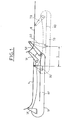
- la figure 2 représente une vue en perspective de l'intérieur d'un véhicule illustrant un agencement d'une porte coulissante conforme à l'invention en position fermée,
- la figure 3 représente une vue en perspective de l'intérieur du véhicule de la figure 2, la porte étant en position ouverte,
- la figure 4 représente une vue de dessus de l'extrémité d'un second bras de maintien de la porte coopérant avec un rail de guidage et illustrant différentes phases d'ouverture/fermeture de la porte des figures 1 à 3,
- la figure 5 représente un détail de la figure 4 illustrant l'extrémité du second bras de maintien de la porte, vu selon la direction F de la figure 4.
- FIG. 1 represents a schematic top view of an arrangement of a sliding door of a motor vehicle according to the invention, in the closed position (solid lines) and in the open position (broken lines),
- FIG. 2 represents a perspective view of the interior of a vehicle illustrating an arrangement of a sliding door according to the invention in the closed position,
- FIG. 3 represents a perspective view of the interior of the vehicle of FIG. 2, the door being in the open position,
- FIG. 4 represents a top view of the end of a second door holding arm cooperating with a guide rail and illustrating different phases of opening / closing of the door of FIGS. 1 to 3,
- FIG. 5 represents a detail in FIG. 4 illustrating the end of the second door holding arm, seen in the direction F of FIG. 4.
La porte 1 coulissante représentée aux figures 1 à 3 est
maintenue et guidée au moyen de trois bras 3, 5, 7 coopérant
en coulissement avec, respectivement, trois rails 4, 6, 8 de
guidage.The sliding
Les mêmes éléments sont désignés par les mêmes
références numériques aux figures 1 à 5, cependant, afin de
mieux illustrer les deux positions extrêmes de la porte 1, les
références numériques des pièces mobiles de l'agencement
ont été complétées à la figure 1 par la lettre F lorsque la porte
1 est en position fermée et par la lettre O lorsque la porte 1
est en position ouverte.The same elements are designated by the same
numerical references to Figures 1 to 5, however, in order to
better illustrate the two extreme positions of
Un premier bras 3 a une extrémité solidaire de la partie
avant basse de la porte 1 et une autre extrémité B qui coulisse
dans un premier rail 4 inférieur solidaire de la structure 2 du
véhicule. L'extrémité B coulissante du premier bras 3
comporte, par exemple, un système à galet rotatif autour d'un
axe sensiblement parallèle au plan de la porte 1.A
Classiquement, le premier rail 4 est cintré vers l'intérieur
du véhicule en direction de l'avant du véhicule, pour participer
aux phases de déboítement et d'emboítement de la porte 1 par
rapport à la structure 2.Conventionally, the
Un second bras 5 a une extrémité articulée sur la
structure 2 et l'autre extrémité C guidée en coulissant dans un
second rail 6 inférieur solidaire de la porte 1. Le second rail 6
est situé sensiblement à proximité du bord inférieur de la
porte 1. L'extrémité C du bras guidée dans le second rail 6
comporte également un système à galets roulant décrits plus
en détail ci-après.A
Enfin, le troisième bras 7 a une extrémité articulée sur la
partie arrière de la porte 1 et l'autre extrémité guidée en
coulissement dans un troisième rail 8 intermédiaire solidaire
de la structure 2. Le troisième rail 8 est situé
approximativement à mi-hauteur de la porte 1, à l'arrière de
l'ouverture 13 prévue pour la porte dans la structure 2.Finally, the
Selon l'invention, les bras 3, 5, 7 de maintien de la porte
ainsi que les rails 4, 6, 8 de guidage de cette dernière sont
dimensionnés et disposés relativement de façon que les
extrémités B, C, A des bras 3, 5, 7 coulissant dans les rails 4,
6, 8 forment les sommets d'un triangle fictif ABC aussi bien
lorsque la porte 1 est en position fermée (figure 1 et 2) que
lorsqu'elle est en position ouverte (1 et 3).According to the invention, the
Le triangle ABC défini par les points de maintien de la
porte 1 est situé, de préférence, dans un plan sensiblement
parallèle au plan de la porte.The triangle ABC defined by the points of maintenance of the
On constate qu'un tel agencement permet un parfait maintien de la porte dans toutes ses positions, ainsi qu'un parfait guidage de cette dernière.We see that such an arrangement allows a perfect holding the door in all its positions, as well as a perfect guidance of the latter.
En particulier, un tel agencement selon l'invention permet une manoeuvre aisée de la porte par un utilisateur tout en présentant des moyens de maintien et de guidage simplifiés par rapport à l'art antérieur.In particular, such an arrangement according to the invention allows easy operation of the door by a user while having simplified holding and guiding means compared to the prior art.
De préférence, les bras 3, 5, 7 de maintien de la porte
ainsi que les rails 4, 6, 8 de guidage de cette dernière sont
dimensionnés et disposés relativement de façon que la
distance L séparant les extrémités B, C coulissantes des
premier 3 et second 5 bras reste continuellement supérieure à
une distance minimale de l'ordre de 150 à 300mm environ. En
particulier, et selon l'invention, la distance L séparant les
extrémités B, C coulissantes des premier 3 et second 5 bras
est comprise entre 150 à 300mm environ lorsque la porte 1 est
en position ouverte (figures 1 et 3)Preferably, the
Cette disposition des moyens de maintien et de guidage confère un parfait fonctionnement et maintien de la porte au cours de son utilisation.This arrangement of the holding and guiding means provides perfect operation and maintenance of the door during its use.
En se référant à présent à la figure 4, l'extrémité
coulissante C du second bras 5 comporte un système à trois
galets 10, 11, 12 rotatifs. Les trois galets 10, 11, 12 sont
agencés relativement de façon que leur axes de rotation
respectifs 110, 111, 112 forment, en projection dans un plan
sensiblement perpendiculaire au plan de la porte 1, les
sommets d'un triangle fixe.Referring now to Figure 4, the end
sliding C of the
Par ailleurs, deux premiers galets 10, 11 roulent
respectivement contre les deux faces opposées d'un même
flanc vertical du second rail 6. Le troisième galet 12 est, quant
à lui, décalé par rapport au deux premiers galets 10, 11 vers
l'arrière du rail 6.Furthermore, two
Le troisième galet 12 est disposé de façon à rouler
sensiblement sur le même côté de rail 6 que l'un 10 des deux
premiers galets 10, 11 lorsque la porte coulisse.The
Comme représenté à la figure 5, le troisième galet 12 est
situé de préférence dans un plan différent des deux autres
galets 10, 11. Par exemple, le troisième galet 12 est situé en
dessous du plan horizontal contenant les deux autres galets
10, 11.As shown in Figure 5, the
De plus, l'extrémité arrière du second rail 6 comporte une
portion 9 repliée vers la porte 1 qui forme une butée pour les
deux premiers galets 10, 11. C'est-à-dire que, lorsque
l'extrémité C du second bras 5 arrive en fin de course à
l'extrémité arrière du second rail 6, le troisième galet 12 quitte
de rail 6 et permet au second bras 5 de déboíter ou d'emboíter
la porte 1 par rapport la structure 2.In addition, the rear end of the
La figure 4 illustre trois positions α, β et γ différentes de
l'extrémité arrière du rail 6 ou cours de la manoeuvre de la
porte 1. Pour mieux illustrer les différentes positions du
second rail 6, la référence numérique de ce dernier a été
complétée par la lettre α, β ou γ correspondant à sa position.Figure 4 illustrates three different positions α, β and γ of
the rear end of the
Dans une première position α (porte ouverte), le rail 6α
est disposé entre d'une part un galet 11 dit intérieur et les
deux autres galets 10, 12 dits extérieurs. Lorsque l'utilisateur
commence à fermer la porte 1, celle-ci coulisse vers l'avant du
véhicule. Le second rail 6 coulisse alors également vers
l'avant entre les galets intérieur 11 et extérieurs 10, 12
(direction T, figure 4). In a first position α (door open), the rail 6α
is placed between on the one hand a
Lorsque l'extrémité arrière 9β du second rail 6β arrive en
fin de course à l'extrémité du second bras 5, le troisième galet
12 (galet extérieur) quitte le rail 6 (deuxième position β), pour
permettre au second bras 5 pivoter vers l'intérieur du véhicule
(flèche P) afin d'emboíter la porte dans la structure (troisième
position γ fermée).When the rear end 9β of the second rail 6β arrives at
limit switch at the end of the
Bien entendu, la manoeuvre d'ouverture de la porte décrit le processus inverse à celui décrit ci-dessus en référence à la figure 4.Of course, the door opening operation described the reverse process to that described above with reference to the figure 4.
Ainsi, en partant d'une position fermée (figures 1 et 2),
l'ouverture de la porte 1 commence un mouvement de
déboítement par rapport à la structure. Pour cela, la second
bras 5 pivote vers l'extérieur dans le sens inverse à la flèche
P de la figure 4 et commence une translation vers l'arrière du
véhicule.Thus, starting from a closed position (Figures 1 and 2),
the opening of
Pour ouvrir complètement la porte l'utilisateur fait
coulisser ensuite cette dernière vers l'arrière (direction
opposée à la flèche T). Pendant cette phase, les premier 3 et
troisième bras 7 coulissent vers l'arrière dans leur rails 4, 8
respectifs tandis que le second bras coulisse vers l'avant dans
le second rail 6.To fully open the door the user does
then slide the latter backwards (direction
opposite arrow T). During this phase, the first 3 and
La position d'ouverture maximale de la porte 1 est définie,
par exemple, par une ou plusieurs butées formées au niveau
des rails de guidage 4, 6, 8. Par exemple, une butée limitant
l'ouverture est formée au niveau de l'extrémité arrière du
premier rail 4 inférieur solidaire de la structure 2 et/ou à
l'extrémité avant du second rail 6.The maximum opening position of
Claims (8)
Applications Claiming Priority (4)
| Application Number | Priority Date | Filing Date | Title |
|---|---|---|---|
| FR0105989 | 2001-05-04 | ||
| FR0105989A FR2824356A1 (en) | 2001-05-04 | 2001-05-04 | Automobile sliding door is held and guided by three arms engaging three guide rails which hold door when in both closed and open positions |
| FR0109413 | 2001-07-13 | ||
| FR0109413A FR2824357B1 (en) | 2001-05-04 | 2001-07-13 | ARRANGEMENT OF A SLIDING DOOR OF A MOTOR VEHICLE |
Publications (2)
| Publication Number | Publication Date |
|---|---|
| EP1255014A1 true EP1255014A1 (en) | 2002-11-06 |
| EP1255014B1 EP1255014B1 (en) | 2005-04-20 |
Family
ID=26213000
Family Applications (1)
| Application Number | Title | Priority Date | Filing Date |
|---|---|---|---|
| EP20020290764 Expired - Fee Related EP1255014B1 (en) | 2001-05-04 | 2002-03-27 | Structure and sliding door of a vehicle |
Country Status (4)
| Country | Link |
|---|---|
| EP (1) | EP1255014B1 (en) |
| DE (1) | DE60203758T2 (en) |
| ES (1) | ES2237653T3 (en) |
| FR (1) | FR2824357B1 (en) |
Cited By (11)
| Publication number | Priority date | Publication date | Assignee | Title |
|---|---|---|---|---|
| FR2865759A1 (en) * | 2004-01-29 | 2005-08-05 | Peugeot Citroen Automobiles Sa | Lateral sliding door for motor vehicle, has guide rail with rectilinear and rear curved end parts, and elastic spring unit and rod stopper to ensure maintenance of swinging rod in unfolded position |
| FR2865758A1 (en) * | 2004-01-29 | 2005-08-05 | Peugeot Citroen Automobiles Sa | Lateral sliding door for motor vehicle, has draw spring and rod stop to ensure maintenance of swaying rod, on which guide roller is mounted, in unfolded position during opening of door |
| FR2890003A1 (en) * | 2005-08-25 | 2007-03-02 | Renault Sas | Motor vehicle, has U-shaped arm connected at rotation to body shell or door around horizontal axis, where door is movably mounted to shell by arm between closed and open positions and axis is parallel to longitudinal direction of vehicle |
| FR2893543A1 (en) * | 2005-11-22 | 2007-05-25 | Peugeot Citroen Automobiles Sa | Motor vehicle, has support and guiding assemblies with carriages mounted on structure, and another support and guiding assembly with another carriage mounted on door, where latter carriage is spaced from former carriages when door is opened |
| EP1911917A1 (en) | 2006-10-09 | 2008-04-16 | CRF Societa'Consortile per Azioni | Motor-vehicle sliding door |
| JP2013163414A (en) * | 2012-02-09 | 2013-08-22 | Aisin Seiki Co Ltd | Slide door device for vehicle |
| EP3315699A1 (en) * | 2016-10-28 | 2018-05-02 | Toyota Jidosha Kabushiki Kaisha | Sliding door structure |
| CN108756583A (en) * | 2018-06-17 | 2018-11-06 | 桂林京达科技有限公司 | A kind of vehicle outer sliding door assembly automatically |
| EP3656957A1 (en) * | 2018-11-21 | 2020-05-27 | Ningbo Geely Automobile Research & Development Co. Ltd. | Sliding door hinge |
| KR20210007303A (en) * | 2019-07-10 | 2021-01-20 | 현대자동차주식회사 | Lower rail double guide structure of opposed type sliding doors |
| KR20210032117A (en) * | 2019-09-16 | 2021-03-24 | 현대자동차주식회사 | Structure for preventing movement of opposed type sliding door |
Citations (5)
| Publication number | Priority date | Publication date | Assignee | Title |
|---|---|---|---|---|
| FR1577398A (en) * | 1967-04-21 | 1969-08-08 | ||
| FR2171805A5 (en) * | 1972-02-10 | 1973-09-21 | Beckett Laycock Watkinson Ltd | |
| FR2285257A1 (en) * | 1974-09-17 | 1976-04-16 | Chausson Usines Sa | Sliding door for goods vehicle - has roller and guide system and swinging arm to move door outwards prior to sliding |
| US4617756A (en) * | 1984-03-26 | 1986-10-21 | Gebr. Bode & Co. Gmbh | Swingable sliding door for a motor vehicle utilizing a swing arm mounted on the body of the car |
| JPH09272343A (en) * | 1996-04-09 | 1997-10-21 | Mitsubishi Automob Eng Co Ltd | Slide door mechanism |
-
2001
- 2001-07-13 FR FR0109413A patent/FR2824357B1/en not_active Expired - Fee Related
-
2002
- 2002-03-27 EP EP20020290764 patent/EP1255014B1/en not_active Expired - Fee Related
- 2002-03-27 DE DE2002603758 patent/DE60203758T2/en not_active Expired - Lifetime
- 2002-03-27 ES ES02290764T patent/ES2237653T3/en not_active Expired - Lifetime
Patent Citations (5)
| Publication number | Priority date | Publication date | Assignee | Title |
|---|---|---|---|---|
| FR1577398A (en) * | 1967-04-21 | 1969-08-08 | ||
| FR2171805A5 (en) * | 1972-02-10 | 1973-09-21 | Beckett Laycock Watkinson Ltd | |
| FR2285257A1 (en) * | 1974-09-17 | 1976-04-16 | Chausson Usines Sa | Sliding door for goods vehicle - has roller and guide system and swinging arm to move door outwards prior to sliding |
| US4617756A (en) * | 1984-03-26 | 1986-10-21 | Gebr. Bode & Co. Gmbh | Swingable sliding door for a motor vehicle utilizing a swing arm mounted on the body of the car |
| JPH09272343A (en) * | 1996-04-09 | 1997-10-21 | Mitsubishi Automob Eng Co Ltd | Slide door mechanism |
Non-Patent Citations (1)
| Title |
|---|
| PATENT ABSTRACTS OF JAPAN vol. 1998, no. 02 30 January 1998 (1998-01-30) * |
Cited By (15)
| Publication number | Priority date | Publication date | Assignee | Title |
|---|---|---|---|---|
| FR2865759A1 (en) * | 2004-01-29 | 2005-08-05 | Peugeot Citroen Automobiles Sa | Lateral sliding door for motor vehicle, has guide rail with rectilinear and rear curved end parts, and elastic spring unit and rod stopper to ensure maintenance of swinging rod in unfolded position |
| FR2865758A1 (en) * | 2004-01-29 | 2005-08-05 | Peugeot Citroen Automobiles Sa | Lateral sliding door for motor vehicle, has draw spring and rod stop to ensure maintenance of swaying rod, on which guide roller is mounted, in unfolded position during opening of door |
| FR2890003A1 (en) * | 2005-08-25 | 2007-03-02 | Renault Sas | Motor vehicle, has U-shaped arm connected at rotation to body shell or door around horizontal axis, where door is movably mounted to shell by arm between closed and open positions and axis is parallel to longitudinal direction of vehicle |
| FR2893543A1 (en) * | 2005-11-22 | 2007-05-25 | Peugeot Citroen Automobiles Sa | Motor vehicle, has support and guiding assemblies with carriages mounted on structure, and another support and guiding assembly with another carriage mounted on door, where latter carriage is spaced from former carriages when door is opened |
| EP1911917A1 (en) | 2006-10-09 | 2008-04-16 | CRF Societa'Consortile per Azioni | Motor-vehicle sliding door |
| EP2626226A3 (en) * | 2012-02-09 | 2015-12-23 | Aisin Seiki Kabushiki Kaisha | Slide door device for vehicle |
| JP2013163414A (en) * | 2012-02-09 | 2013-08-22 | Aisin Seiki Co Ltd | Slide door device for vehicle |
| EP3315699A1 (en) * | 2016-10-28 | 2018-05-02 | Toyota Jidosha Kabushiki Kaisha | Sliding door structure |
| CN108016261A (en) * | 2016-10-28 | 2018-05-11 | 丰田自动车株式会社 | Slide door structure |
| US10480232B2 (en) | 2016-10-28 | 2019-11-19 | Toyota Jidosha Kabushiki Kaisha | Sliding door structure |
| CN108756583A (en) * | 2018-06-17 | 2018-11-06 | 桂林京达科技有限公司 | A kind of vehicle outer sliding door assembly automatically |
| EP3656957A1 (en) * | 2018-11-21 | 2020-05-27 | Ningbo Geely Automobile Research & Development Co. Ltd. | Sliding door hinge |
| KR20210007303A (en) * | 2019-07-10 | 2021-01-20 | 현대자동차주식회사 | Lower rail double guide structure of opposed type sliding doors |
| KR20210032117A (en) * | 2019-09-16 | 2021-03-24 | 현대자동차주식회사 | Structure for preventing movement of opposed type sliding door |
| KR102603543B1 (en) | 2019-09-16 | 2023-11-20 | 현대자동차주식회사 | Structure for preventing movement of opposed type sliding door |
Also Published As
| Publication number | Publication date |
|---|---|
| DE60203758D1 (en) | 2005-05-25 |
| DE60203758T2 (en) | 2006-03-02 |
| FR2824357B1 (en) | 2004-01-23 |
| EP1255014B1 (en) | 2005-04-20 |
| ES2237653T3 (en) | 2005-08-01 |
| FR2824357A1 (en) | 2002-11-08 |
Similar Documents
| Publication | Publication Date | Title |
|---|---|---|
| FR2842467A1 (en) | REAR BEARING SYSTEM FOR DISCOVERABLE VEHICLE WITH FOLDABLE RIGID ROOF | |
| EP1255014A1 (en) | Sliding door arrangement for vehicle | |
| FR2759640A1 (en) | HARDTOP FOR CONVERTIBLE | |
| EP1613495B1 (en) | Retractable parcel shelf system for a convertible vehicle with a folding roof | |
| EP1765624B1 (en) | Motor vehicle opening frame and motor vehicle equipped with same | |
| FR2807714A1 (en) | Sliding roof system for convertible vehicle has rear roof element central element linked on each side to body by pivoting arms and articulated on front and rear pivot pins of pivoting arms | |
| EP1369276A1 (en) | Rear bootlid for automobile | |
| EP1501694B1 (en) | Retractable package shelf system for convertible vehicle with folding roof | |
| FR2824356A1 (en) | Automobile sliding door is held and guided by three arms engaging three guide rails which hold door when in both closed and open positions | |
| EP1556239B1 (en) | Modular assembly for vehicle with retractable roof and corresponding vehicle | |
| FR2896188A1 (en) | Retractable roof for roadster type vehicle, has guiding unit permitting to displace retractable panel in translation under rear crosspiece and to arrange panel in position where panel extends parallel to upper surface of boot cover | |
| EP1198362B1 (en) | Retractable roof system | |
| FR2877280A1 (en) | Seat for motor vehicle, has base mounted on displacement device that has guiding mechanism permitting guiding of movement of base in translation simultaneously along two axes | |
| EP1151880A1 (en) | Convertible door for motor vehicle | |
| EP1944180A1 (en) | Mechanism for moving a mobile roof | |
| FR2828838A1 (en) | Sedan convertible into pick up comprises compartment delimited by floor, partly retractable roof, rear door with window and panel, roof formed by transverse slats able to move rearwards | |
| FR2859957A1 (en) | Rear parcel shelf system for convertible vehicle, has pin, sensing device and cam allowing rear of shelf to be pressed against front side of cover, when shelf reaches deployed position | |
| EP1093971A1 (en) | Load-carrier for a vehicle and vehicle with such a carrier | |
| FR2879968A1 (en) | Vehicle with sliding side door has transverse telescopic arm to open and close door with head sliding in door rail | |
| EP1077147A1 (en) | Sliding door assembly on a vehicle | |
| FR2859956A1 (en) | Rear parcel shelf system for convertible vehicle, has shelf for covering space situated behind back rest of seat, in position corresponding to closed position of foldable roof, where shelf pivots with respect to rear roof unit | |
| FR2897558A1 (en) | Retractable roof for roadster type vehicle, has guiding units displacing panel below rear crosspiece and having synchronization units for displacement of telescopic slides between them, where units are slides connected to panel and case | |
| FR2648878A1 (en) | Device for retaining a member which can move rotationally with respect to a stationary member and motor vehicle rear parcel shelf equipped with such a device | |
| FR2879513A1 (en) | Vehicle, has door connected to body shell by connection unit, where connection unit is arranged such that door has different inclination with respect to vertical direction between opening and closed positions | |
| FR2846603A1 (en) | Retractable rear shelf for automobile with folding roof comprises cam roller on each lateral edge which engage complementary cams fixed to bodywork and guide shelf in predetermined trajectory between normal and stowed positions |
Legal Events
| Date | Code | Title | Description |
|---|---|---|---|
| PUAI | Public reference made under article 153(3) epc to a published international application that has entered the european phase |
Free format text: ORIGINAL CODE: 0009012 |
|
| AK | Designated contracting states |
Kind code of ref document: A1 Designated state(s): AT BE CH CY DE DK ES FI FR GB GR IE IT LI LU MC NL PT SE TR |
|
| AX | Request for extension of the european patent |
Free format text: AL;LT;LV;MK;RO;SI |
|
| 17P | Request for examination filed |
Effective date: 20021121 |
|
| 17Q | First examination report despatched |
Effective date: 20030401 |
|
| AKX | Designation fees paid |
Designated state(s): DE ES FR GB IT |
|
| GRAP | Despatch of communication of intention to grant a patent |
Free format text: ORIGINAL CODE: EPIDOSNIGR1 |
|
| RTI1 | Title (correction) |
Free format text: STRUCTURE AND SLIDING DOOR OF A VEHICLE |
|
| GRAS | Grant fee paid |
Free format text: ORIGINAL CODE: EPIDOSNIGR3 |
|
| GRAA | (expected) grant |
Free format text: ORIGINAL CODE: 0009210 |
|
| AK | Designated contracting states |
Kind code of ref document: B1 Designated state(s): DE ES FR GB IT |
|
| REG | Reference to a national code |
Ref country code: GB Ref legal event code: FG4D Free format text: NOT ENGLISH |
|
| GBT | Gb: translation of ep patent filed (gb section 77(6)(a)/1977) |
Effective date: 20050420 |
|
| REF | Corresponds to: |
Ref document number: 60203758 Country of ref document: DE Date of ref document: 20050525 Kind code of ref document: P |
|
| REG | Reference to a national code |
Ref country code: ES Ref legal event code: FG2A Ref document number: 2237653 Country of ref document: ES Kind code of ref document: T3 |
|
| PLBE | No opposition filed within time limit |
Free format text: ORIGINAL CODE: 0009261 |
|
| STAA | Information on the status of an ep patent application or granted ep patent |
Free format text: STATUS: NO OPPOSITION FILED WITHIN TIME LIMIT |
|
| 26N | No opposition filed |
Effective date: 20060123 |
|
| REG | Reference to a national code |
Ref country code: GB Ref legal event code: 746 Effective date: 20070117 |
|
| PGFP | Annual fee paid to national office [announced via postgrant information from national office to epo] |
Ref country code: ES Payment date: 20080307 Year of fee payment: 7 |
|
| REG | Reference to a national code |
Ref country code: ES Ref legal event code: FD2A Effective date: 20090328 |
|
| PG25 | Lapsed in a contracting state [announced via postgrant information from national office to epo] |
Ref country code: ES Free format text: LAPSE BECAUSE OF NON-PAYMENT OF DUE FEES Effective date: 20090328 |
|
| PGFP | Annual fee paid to national office [announced via postgrant information from national office to epo] |
Ref country code: IT Payment date: 20140225 Year of fee payment: 13 |
|
| PGFP | Annual fee paid to national office [announced via postgrant information from national office to epo] |
Ref country code: GB Payment date: 20140226 Year of fee payment: 13 |
|
| REG | Reference to a national code |
Ref country code: FR Ref legal event code: PLFP Year of fee payment: 14 |
|
| PGFP | Annual fee paid to national office [announced via postgrant information from national office to epo] |
Ref country code: DE Payment date: 20150219 Year of fee payment: 14 |
|
| PGFP | Annual fee paid to national office [announced via postgrant information from national office to epo] |
Ref country code: FR Payment date: 20150319 Year of fee payment: 14 |
|
| GBPC | Gb: european patent ceased through non-payment of renewal fee |
Effective date: 20150327 |
|
| PG25 | Lapsed in a contracting state [announced via postgrant information from national office to epo] |
Ref country code: IT Free format text: LAPSE BECAUSE OF NON-PAYMENT OF DUE FEES Effective date: 20150327 |
|
| PG25 | Lapsed in a contracting state [announced via postgrant information from national office to epo] |
Ref country code: GB Free format text: LAPSE BECAUSE OF NON-PAYMENT OF DUE FEES Effective date: 20150327 |
|
| REG | Reference to a national code |
Ref country code: DE Ref legal event code: R119 Ref document number: 60203758 Country of ref document: DE |
|
| REG | Reference to a national code |
Ref country code: FR Ref legal event code: ST Effective date: 20161130 |
|
| PG25 | Lapsed in a contracting state [announced via postgrant information from national office to epo] |
Ref country code: DE Free format text: LAPSE BECAUSE OF NON-PAYMENT OF DUE FEES Effective date: 20161001 Ref country code: FR Free format text: LAPSE BECAUSE OF NON-PAYMENT OF DUE FEES Effective date: 20160331 |