EP1254328B1 - Getriebe mit zentraler kupplungsausrückung - Google Patents
Getriebe mit zentraler kupplungsausrückung Download PDFInfo
- Publication number
- EP1254328B1 EP1254328B1 EP01909707A EP01909707A EP1254328B1 EP 1254328 B1 EP1254328 B1 EP 1254328B1 EP 01909707 A EP01909707 A EP 01909707A EP 01909707 A EP01909707 A EP 01909707A EP 1254328 B1 EP1254328 B1 EP 1254328B1
- Authority
- EP
- European Patent Office
- Prior art keywords
- clutch
- transmission
- release
- transmission control
- control unit
- Prior art date
- Legal status (The legal status is an assumption and is not a legal conclusion. Google has not performed a legal analysis and makes no representation as to the accuracy of the status listed.)
- Expired - Lifetime
Links
Images

Classifications
-
- F—MECHANICAL ENGINEERING; LIGHTING; HEATING; WEAPONS; BLASTING
- F16—ENGINEERING ELEMENTS AND UNITS; GENERAL MEASURES FOR PRODUCING AND MAINTAINING EFFECTIVE FUNCTIONING OF MACHINES OR INSTALLATIONS; THERMAL INSULATION IN GENERAL
- F16D—COUPLINGS FOR TRANSMITTING ROTATION; CLUTCHES; BRAKES
- F16D28/00—Electrically-actuated clutches
-
- F—MECHANICAL ENGINEERING; LIGHTING; HEATING; WEAPONS; BLASTING
- F16—ENGINEERING ELEMENTS AND UNITS; GENERAL MEASURES FOR PRODUCING AND MAINTAINING EFFECTIVE FUNCTIONING OF MACHINES OR INSTALLATIONS; THERMAL INSULATION IN GENERAL
- F16H—GEARING
- F16H61/00—Control functions within control units of change-speed- or reversing-gearings for conveying rotary motion ; Control of exclusively fluid gearing, friction gearing, gearings with endless flexible members or other particular types of gearing
- F16H2061/0046—Details of fluid supply channels, e.g. within shafts, for supplying friction devices or transmission actuators with control fluid
-
- F—MECHANICAL ENGINEERING; LIGHTING; HEATING; WEAPONS; BLASTING
- F16—ENGINEERING ELEMENTS AND UNITS; GENERAL MEASURES FOR PRODUCING AND MAINTAINING EFFECTIVE FUNCTIONING OF MACHINES OR INSTALLATIONS; THERMAL INSULATION IN GENERAL
- F16H—GEARING
- F16H63/00—Control outputs from the control unit to change-speed- or reversing-gearings for conveying rotary motion or to other devices than the final output mechanism
- F16H63/40—Control outputs from the control unit to change-speed- or reversing-gearings for conveying rotary motion or to other devices than the final output mechanism comprising signals other than signals for actuating the final output mechanisms
- F16H63/46—Signals to a clutch outside the gearbox
Definitions
- the invention relates to a transmission with a central Clutch release according to the preamble of the claim 1.
- the clutch disengagement of transmissions can be done externally on the clutch bell arranged clutch actuator or by central units arranged on the input shaft of the transmission Clutch release devices are carried out. at the latter variant does not have the translating lever, the between the clutch and the clutch actuator is provided. The lever creates a strengthening of the force generated by the clutch actuator to that on the clutch force required to pull the clutch disc from the flywheel between the engine and the transmission.
- German application DE 198 26 068.7 there is one central clutch release described in the central order the input shaft of the gearbox an actuating cylinder for the actuating medium and a displacement measuring device are arranged are.
- the valves are located outside the gearbox and must have a corresponding line with the actuating cylinder get connected.
- EP 0 824 644 known a transmission control for vehicle transmissions or is arranged in the transmission and with actuators the switching devices for the transmission cooperates.
- the Transmission control has both mechanical and electronic Items on.
- the transmission control is involved a clutch disengagement or clutch control not together.
- the invention is based on the prior art based on the task of a centrally acting clutch release to propose for a transmission, the existing one Disadvantages eliminated, and, in particular, space-saving and modular can be built.
- a centrally acting device proposed to disengage the clutch between the Clutch disc and the clutch bell arranged in this way is that the connecting line for the actuating medium and the electrical connection line for the clutch control is directly connectable to the transmission control.
- the medium for actuating the clutch is immediately out taken from the transmission control.
- the medium is preferred Air because air is the operating medium in commercial vehicles for the brakes, for example.
- the outer diameter is sufficient the device for disengaging the clutch to the transmission control.
- An embodiment has plug connections on the device for disengagement the clutch and the transmission control on that immediately are interconnectable.
- An embodiment is in the disengagement device the clutch controls the clutch integrated and in The solenoid valves for actuation are also one embodiment disengagement of the clutch in the device provided for disengaging the clutch.
- Another embodiment shows the control of the clutch integrated in the transmission control system, with the solenoid valves also in one form to control the clutch disengagement in the transmission control are provided.
- the short connections between the transmission control and the device for disengaging the clutch allow a high dynamic when the clutch is actuated.
- the device described is suitable for both a pressed and a pulled separating clutch.
- the coupling is preferably a dry coupling, but with an appropriate seal the application is also possible for a wet coupling.
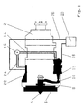
- a clutch 6 is arranged on the input shaft 4 of the transmission 2 and can be brought into an opened and a closed state with the flywheel of a drive machine of the vehicle (not shown here) by a release bearing 8 arranged on the input shaft 4.
- a connection line 14 is provided on the clutch actuator 12, which connects the clutch actuator 12 to a memory 16 for the actuating medium of the clutch.
- An electrical connection line 18 connects the clutch actuator 12 to an electronic control device 20.
- This control device 20 can also be the host computer of the vehicle.
- a transmission control 22 is arranged in the transmission 20, which is also connected to the memory 16 via a line 24 and which is connected to the control device 20 via a line 26.
- Fig. 2 shows a transmission 2 for a here too not shown vehicle .
- the clutch 6 On the input shaft 4 of the Transmission 2, the clutch 6 is arranged by the on the input shaft 4 arranged release bearing 8 in one opened and a closed state can.
- Disengaging clutch 28 engages around the input shaft is delegated around.
- the Device 28 on connectors 30 On its outer circumference, the Device 28 on connectors 30 through which the device 28 and the transmission control 22 connected to each other are.
- the plug connections can be used for the actuating medium sealed plugs and couplings, such as they are generally known for hose lines from pneumatics are.
- the plug connection for the electrical transmission preferably consists of a round, multi-pole Plug, the halves screwed together for securing can be. Received via the plug connections the device 28 the necessary electrical signals and the auxiliary medium for actuating and disengaging the clutch.
Landscapes
- Engineering & Computer Science (AREA)
- General Engineering & Computer Science (AREA)
- Physics & Mathematics (AREA)
- Electromagnetism (AREA)
- Mechanical Engineering (AREA)
- Hydraulic Clutches, Magnetic Clutches, Fluid Clutches, And Fluid Joints (AREA)
- Mechanical Operated Clutches (AREA)
- Control Of Driving Devices And Active Controlling Of Vehicle (AREA)
- Gear-Shifting Mechanisms (AREA)
Description
Die beschriebene Vorrichtung eignet sich sowohl für eine gedrückte wie auch eine gezogene Trennkupplung. Die Kupplung ist dabei vorzugsweise eine Trockenkupplung, jedoch ist bei einer entsprechenden Abdichtung die Anwendung auch für eine nasse Kupplung möglich.
Es zeigen:
- Fig. 1
- eine Anordnung nach dem Stand der Technik und
- Fig. 2
- eine erfindungsgemäße Anordnung.
In dem Getriebe 20 ist eine Getriebesteuerung 22 angeordnet, die über eine Leitung 24 ebenfalls mit dem Speicher 16 verbunden ist und die über eine Leitung 26 an die Steuereinrichtung 20 angeschlossen ist.
- 2
- Getriebe
- 4
- Eingangswelle
- 6
- Kupplung
- 8
- Ausrücklager
- 10
- Hebel
- 12
- Kupplungssteller
- 14
- Verbindungsleitung
- 16
- Speicher
- 18
- Verbindungsleitung
- 20
- Steuereinrichtung
- 22
- Getriebesteuerung
- 24
- Leitung
- 26
- Leitung
- 28
- Vorrichtung
- 30
- Steckverbindung
Claims (8)
- Fahrzeuggetriebe (2) mit einer zentral wirkenden Vorrichtung (28) zur Ausrückung der Kupplung (6), die zwischen der Kupplungsscheibe und der Kupplungsglocke des Getriebes (2) vorgesehen und elektrisch unmittelbar mit einer Getriebesteuerung (22) verbunden ist, die an oder in dem Getriebe (2) vorgesehen ist, dadurch gekennzeichnet, daß die Kupplung (6) nicht elektrisch betätigt ist und das Medium zur Betätigung der Kupplung (6) unmittelbar aus der Getriebesteuerung (22) entnommen ist.
- Fahrzeuggetriebe (2) mit einer zentral wirkenden Vorrichtung (28) zur Ausrückung der Kupplung (6) nach Anspruch 1, dadurch gekennzeichnet, daß der Außendurchmesser der Vorrichtung (28) bis an die Getriebesteuerung (22) heranreicht.
- Fahrzeuggetriebe (2) mit einer zentral wirkenden Vorrichtung (28) zur Ausrückung der Kupplung (6) nach Anspruch 1 oder 2, dadurch gekennzeichnet, daß Steckverbindungen (30) an der Vorrichtung (28) und an der Getriebesteuerung (22) vorgesehen sind, die unmittelbar miteinander verbindbar sind.
- Fahrzeuggetriebe (2) mit einer zentral wirkenden Vorrichtung (28) zur Ausrückung der Kupplung (6) nach einem der Ansprüche 1 bis 3, dadurch gekennzeichnet, daß in der Vorrichtung (28) die Steuerung der Kupplung (6) integriert ist.
- Fahrzeuggetriebe (2) mit einer zentral wirkenden Vorrichtung (28) zur Ausrückung der Kupplung (6) nach einem der Ansprüche 1 bis 4, dadurch gekennzeichnet, daß in der Vorrichtung (28) Magnetventile zur Ansteuerung der Ausrückung der Kupplung (6) vorgesehen sind.
- Fahrzeuggetriebe (2) mit einer zentral wirkenden Vorrichtung (28) zur Ausrückung der Kupplung (6) nach einem der Ansprüche 1 bis 3, dadurch gekennzeichnet, daß in der Getriebesteuerung (22) die Steuerung der Vorrichtung (28) integriert ist.
- Fahrzeuggetriebe (2) mit einer zentral wirkenden Vorrichtung (28) zur Ausrückung der Kupplung (6) nach einem der Ansprüche 1 bis 4 oder 6, dadurch gekennzeichnet, daß in der Getriebesteuerung (22) Magnetventile zur Ansteuerung der Vorrichtung (28) vorgesehen sind.
- Fahrzeuggetriebe (2) mit einer zentral wirkenden Vorrichtung (28) zur Ausrückung der Kupplung (6) nach einem der vorherigen Ansprüche, dadurch gekennzeichnet, daß das Betätigungsmedium Luft ist.
Applications Claiming Priority (3)
| Application Number | Priority Date | Filing Date | Title |
|---|---|---|---|
| DE10005086A DE10005086A1 (de) | 2000-02-04 | 2000-02-04 | Getriebe mit zentraler Kupplungsausrückung |
| DE10005086 | 2000-02-04 | ||
| PCT/EP2001/000966 WO2001057419A1 (de) | 2000-02-04 | 2001-01-30 | Getriebe mit zentraler kupplungsausrückung |
Publications (3)
| Publication Number | Publication Date |
|---|---|
| EP1254328A1 EP1254328A1 (de) | 2002-11-06 |
| EP1254328B1 true EP1254328B1 (de) | 2003-05-14 |
| EP1254328B2 EP1254328B2 (de) | 2006-05-31 |
Family
ID=7629930
Family Applications (1)
| Application Number | Title | Priority Date | Filing Date |
|---|---|---|---|
| EP01909707A Expired - Lifetime EP1254328B2 (de) | 2000-02-04 | 2001-01-30 | Getriebe mit zentraler kupplungsausrückung |
Country Status (6)
| Country | Link |
|---|---|
| US (1) | US7032730B2 (de) |
| EP (1) | EP1254328B2 (de) |
| JP (1) | JP2003521656A (de) |
| BR (1) | BR0107806B1 (de) |
| DE (2) | DE10005086A1 (de) |
| WO (1) | WO2001057419A1 (de) |
Families Citing this family (10)
| Publication number | Priority date | Publication date | Assignee | Title |
|---|---|---|---|---|
| DE10259880B4 (de) * | 2002-12-20 | 2014-07-10 | Zf Friedrichshafen Ag | Vorrichtung zur Betätigung der Kupplung in einem automatisierten oder teilautomatisierten Getriebe |
| DE102005015482A1 (de) * | 2005-04-05 | 2006-10-19 | Daimlerchrysler Ag | Schaltmodul eines automatisierten Getriebes eines Kraftfahrzeugs |
| DE102005021760A1 (de) | 2005-05-11 | 2006-11-16 | Zf Friedrichshafen Ag | Mehrgruppengetriebe |
| DE102005021761A1 (de) * | 2005-05-11 | 2006-11-30 | Zf Friedrichshafen Ag | Mehrgruppengetriebe |
| DE102006024010A1 (de) | 2006-05-23 | 2007-11-29 | Zf Friedrichshafen Ag | Kupplungssteller und Verfahren zur Betätigung einer Kupplung |
| DE102006037958A1 (de) * | 2006-08-12 | 2008-02-14 | Zf Friedrichshafen Ag | Kupplungseinrichtung |
| DE102006040136A1 (de) * | 2006-08-26 | 2008-03-06 | Zf Friedrichshafen Ag | Automatisiertes Schaltgetriebe |
| US8306707B2 (en) | 2007-11-08 | 2012-11-06 | Parker-Hannifin Corporation | Transmission shifting with speed dither and torque dither |
| JP5500018B2 (ja) * | 2010-09-21 | 2014-05-21 | 日産自動車株式会社 | 車両のクラッチ制御装置 |
| DE102019201020A1 (de) * | 2019-01-28 | 2020-07-30 | Knorr-Bremse Systeme für Nutzfahrzeuge GmbH | Gehäuse einer Magnetventileinheit, Magnetventileinheit, Kupplungsbestätigungseinheit, Fahrzeugkupplungseinheit und Verfahren zum Montieren der Magnetventileinheit |
Citations (7)
| Publication number | Priority date | Publication date | Assignee | Title |
|---|---|---|---|---|
| US4271728A (en) * | 1977-04-11 | 1981-06-09 | Nippon Soken, Inc. | Automatic transmission system |
| DE4120540C1 (de) * | 1991-06-21 | 1992-11-05 | Dr.Ing.H.C. F. Porsche Ag, 7000 Stuttgart, De | |
| DE9307228U1 (de) * | 1993-05-12 | 1993-07-15 | Siemens AG, 8000 München | Steuersystem, insbesondere Getriebesteuerungssystem für ein Kraftfahrzeug |
| DE19716600A1 (de) * | 1996-06-12 | 1997-12-18 | Mannesmann Sachs Ag | Betätigungseinrichtung für die Betätigung, insbesondere pneumatische Betätigung einer Reibungskupplung |
| DE19815666A1 (de) * | 1997-05-15 | 1998-11-19 | Mannesmann Sachs Ag | Stellantrieb mit Ventileinheiten zur Betätigung einer Reibungskupplung und eines automatisierten Schaltgetriebes |
| DE19735759A1 (de) * | 1997-08-18 | 1999-02-25 | Audi Ag | Verfahren zum Steuern einer automatischen Antriebsvorrichtung |
| DE19826068A1 (de) * | 1998-06-12 | 1999-12-16 | Zahnradfabrik Friedrichshafen | Gemeinsame Betätigung von Kupplung und Getriebebremse |
Family Cites Families (16)
| Publication number | Priority date | Publication date | Assignee | Title |
|---|---|---|---|---|
| DE1132810B (de) * | 1958-03-19 | 1962-07-05 | Zahnradfabrik Friedrichshafen | Durch Druckmittel betaetigbare Schaltvorrichtung fuer Stufenwechselgetriebe, insbesondere von Kraftfahrzeugen |
| JPS5241423B1 (de) * | 1971-04-16 | 1977-10-18 | ||
| US4684003A (en) * | 1983-09-30 | 1987-08-04 | Automotive Products Plc | Concentric slave cylinder for motor vehicle clutch control mechanism |
| DE3820874A1 (de) | 1987-06-27 | 1989-01-05 | Zahnradfabrik Friedrichshafen | Kupplungseinrichtung |
| US5267637A (en) * | 1992-08-17 | 1993-12-07 | Automotive Products Plc | Actuator with anti-rotation spring |
| US5513732A (en) * | 1994-08-05 | 1996-05-07 | Ford Motor Company | Regulation of hydraulic pressure in a system having multiple pressure sources |
| US5722519A (en) * | 1994-10-14 | 1998-03-03 | Ford Global Technologies, Inc. | Multiple ratio automatic transmission and torque converter |
| US5508916A (en) * | 1995-02-13 | 1996-04-16 | Eaton Corporation | Control for engagement of positive clutches in automated mechanical transmission systems |
| DE19517491A1 (de) | 1995-05-12 | 1996-11-14 | Zahnradfabrik Friedrichshafen | Kühlung für eine Getriebesteuerung |
| WO1997002963A2 (de) | 1995-07-12 | 1997-01-30 | Luk Getriebe-Systeme Gmbh | Kupplungs- und getriebebetätigungsvorrichtung |
| BR9606640A (pt) * | 1995-09-12 | 1997-09-30 | Luk Getriebe Systeme Gmbh | Veículo automotor com um equipamento para o acionamento do sistema de transmissão de momento de rotação e da caixa de mudança |
| JP3787921B2 (ja) * | 1996-10-24 | 2006-06-21 | アイシン精機株式会社 | トルクコンバータのロックアップ油圧制御装置 |
| US6205887B1 (en) * | 1997-02-06 | 2001-03-27 | Audi Ag | Automatic electrohydraulically controlled transmission |
| BR9801614A (pt) | 1997-05-15 | 1999-04-13 | Mannesmann Sachs Ag | Mecanismo regulador com válvulas para a ativação de uma embreagem de fricção e de um câmbio automatizado |
| DE19729096A1 (de) | 1997-07-08 | 1998-09-24 | Bosch Gmbh Robert | Anordnung in einem Kraftfahrzeug mit einem Getriebesteller und einem Kupplungssteller |
| DE19832015B4 (de) * | 1997-08-06 | 2012-11-15 | Schaeffler Technologies AG & Co. KG | Betätigungsvorrichtung |
-
2000
- 2000-02-04 DE DE10005086A patent/DE10005086A1/de not_active Withdrawn
-
2001
- 2001-01-30 BR BRPI0107806-2A patent/BR0107806B1/pt not_active IP Right Cessation
- 2001-01-30 EP EP01909707A patent/EP1254328B2/de not_active Expired - Lifetime
- 2001-01-30 US US10/181,121 patent/US7032730B2/en not_active Expired - Fee Related
- 2001-01-30 DE DE50100246T patent/DE50100246D1/de not_active Expired - Lifetime
- 2001-01-30 JP JP2001556030A patent/JP2003521656A/ja not_active Withdrawn
- 2001-01-30 WO PCT/EP2001/000966 patent/WO2001057419A1/de not_active Ceased
Patent Citations (7)
| Publication number | Priority date | Publication date | Assignee | Title |
|---|---|---|---|---|
| US4271728A (en) * | 1977-04-11 | 1981-06-09 | Nippon Soken, Inc. | Automatic transmission system |
| DE4120540C1 (de) * | 1991-06-21 | 1992-11-05 | Dr.Ing.H.C. F. Porsche Ag, 7000 Stuttgart, De | |
| DE9307228U1 (de) * | 1993-05-12 | 1993-07-15 | Siemens AG, 8000 München | Steuersystem, insbesondere Getriebesteuerungssystem für ein Kraftfahrzeug |
| DE19716600A1 (de) * | 1996-06-12 | 1997-12-18 | Mannesmann Sachs Ag | Betätigungseinrichtung für die Betätigung, insbesondere pneumatische Betätigung einer Reibungskupplung |
| DE19815666A1 (de) * | 1997-05-15 | 1998-11-19 | Mannesmann Sachs Ag | Stellantrieb mit Ventileinheiten zur Betätigung einer Reibungskupplung und eines automatisierten Schaltgetriebes |
| DE19735759A1 (de) * | 1997-08-18 | 1999-02-25 | Audi Ag | Verfahren zum Steuern einer automatischen Antriebsvorrichtung |
| DE19826068A1 (de) * | 1998-06-12 | 1999-12-16 | Zahnradfabrik Friedrichshafen | Gemeinsame Betätigung von Kupplung und Getriebebremse |
Also Published As
| Publication number | Publication date |
|---|---|
| WO2001057419A8 (de) | 2001-12-13 |
| US7032730B2 (en) | 2006-04-25 |
| DE10005086A1 (de) | 2001-08-09 |
| JP2003521656A (ja) | 2003-07-15 |
| WO2001057419A1 (de) | 2001-08-09 |
| EP1254328B2 (de) | 2006-05-31 |
| BR0107806A (pt) | 2002-10-29 |
| BR0107806B1 (pt) | 2009-05-05 |
| DE50100246D1 (de) | 2003-06-18 |
| US20030010590A1 (en) | 2003-01-16 |
| EP1254328A1 (de) | 2002-11-06 |
Similar Documents
| Publication | Publication Date | Title |
|---|---|---|
| EP0722394B1 (de) | Steuerungsanordnung für ein kraftfahrzeug | |
| DE10248843B4 (de) | Vorrichtung zum Steuern eines Motors oder Getriebes | |
| DE10191127B4 (de) | Kraftfahrzeug mit einem Antriebsmotor, einer Drehmomentübertragungseinrichtung, wie Kupplung, mit einer Betätigungseinrichtung, einem Getriebe mit zumindest einer Schaltwelle, einer Betätigungseinrichtung und einer Steuereinrichtung | |
| DE102020204459A1 (de) | Hydraulikblock für ein Hydraulikaggregat einer hydraulischen Fremdkraft-Fahrzeugbremsanlage | |
| DE102009053817C5 (de) | Fahrzeug mit einer Bremsmoment von Hinterrädern auf die Vorderräder übertragenden Bremseinrichtung mit Bremsschlupfregelung | |
| EP2087260B2 (de) | Vorrichtung zum sensieren von getriebeschaltpositionen | |
| EP1254328B2 (de) | Getriebe mit zentraler kupplungsausrückung | |
| EP1222414A1 (de) | Getriebebaueinheit und steuerplattform für den einsatz in einer getriebbaueinheit | |
| EP2328766B1 (de) | Elektropneumatische steueranordnung für eine niveauregulierung eines fahrzeuges | |
| EP1290362B1 (de) | Elektro-pneumatische schalteinheit | |
| EP1880126B1 (de) | Mehrgruppengetriebe | |
| DE69307269T2 (de) | Luftzufuhrvorrichtung für Brennkraftmaschine | |
| DE102009054874A1 (de) | Parksperrenvorrichtung mit Notbetätigungsvorrichtung für ein Fahrzeuggetriebe | |
| DE19529665C2 (de) | Steuereinrichtung für ein Kraftfahrzeug mit einem automatischen Getriebe | |
| WO2005078318A1 (de) | Schalteinheit | |
| DE10310235B4 (de) | Steuereinrichtung für Anhängefahrzeug | |
| WO2018171837A1 (de) | Betätigungsmodul für kupplungen und gangstellersysteme und getriebe mit betätigungsmodul | |
| DE102016219462A1 (de) | Hybridmodul und Antriebsstrang für ein Kraftfahrzeug | |
| EP0989292B1 (de) | Elektromotorisches Stellglied, insbesondere mit einer Drosselklappe | |
| DE19513004C2 (de) | Steuer- und Überwachungseinrichtung für Bremssysteme von Schienenfahrzeugen | |
| EP1180602B1 (de) | Steuerventileinrichtung sowie als Bestandteil derselben geeignetes Ventil | |
| DE19630155A1 (de) | Automatgetriebe | |
| EP1054192A1 (de) | Getriebebaueinheit und Vorrichtung zur elektronischen Steuerung einer Getriebebaueinheit | |
| DE19715528A1 (de) | Pneumatische Steuervorrichtung | |
| DE102013012402A1 (de) | Betätigungseinrichtung für ein Schaltgetriebe sowie eine Kupplungseinheit eines Nutzfahrzeuges |
Legal Events
| Date | Code | Title | Description |
|---|---|---|---|
| PUAI | Public reference made under article 153(3) epc to a published international application that has entered the european phase |
Free format text: ORIGINAL CODE: 0009012 |
|
| 17P | Request for examination filed |
Effective date: 20020515 |
|
| AK | Designated contracting states |
Kind code of ref document: A1 Designated state(s): AT BE CH CY DE DK ES FI FR GB GR IE IT LI LU MC NL PT SE TR |
|
| AX | Request for extension of the european patent |
Free format text: AL;LT;LV;MK;RO;SI |
|
| GRAH | Despatch of communication of intention to grant a patent |
Free format text: ORIGINAL CODE: EPIDOS IGRA |
|
| RIC1 | Information provided on ipc code assigned before grant |
Free format text: 7F 16H 61/00 A, 7F 16D 25/12 B, 7B 60K 41/22 B, 7F 16D 48/06 B |
|
| GRAH | Despatch of communication of intention to grant a patent |
Free format text: ORIGINAL CODE: EPIDOS IGRA |
|
| GRAA | (expected) grant |
Free format text: ORIGINAL CODE: 0009210 |
|
| AK | Designated contracting states |
Designated state(s): DE IT SE |
|
| REG | Reference to a national code |
Ref country code: SE Ref legal event code: TRGR |
|
| REG | Reference to a national code |
Ref country code: IE Ref legal event code: FG4D Free format text: GERMAN |
|
| REF | Corresponds to: |
Ref document number: 50100246 Country of ref document: DE Date of ref document: 20030618 Kind code of ref document: P |
|
| PLBQ | Unpublished change to opponent data |
Free format text: ORIGINAL CODE: EPIDOS OPPO |
|
| PLBI | Opposition filed |
Free format text: ORIGINAL CODE: 0009260 |
|
| REG | Reference to a national code |
Ref country code: IE Ref legal event code: FD4D Ref document number: 1254328E Country of ref document: IE |
|
| 26 | Opposition filed |
Opponent name: WABCO GMBH Effective date: 20031218 |
|
| PLBI | Opposition filed |
Free format text: ORIGINAL CODE: 0009260 |
|
| PLAX | Notice of opposition and request to file observation + time limit sent |
Free format text: ORIGINAL CODE: EPIDOSNOBS2 |
|
| 26 | Opposition filed |
Opponent name: DAIMLERCHRYSLER AG Effective date: 20040216 Opponent name: WABCO GMBH Effective date: 20031218 |
|
| PLBB | Reply of patent proprietor to notice(s) of opposition received |
Free format text: ORIGINAL CODE: EPIDOSNOBS3 |
|
| PUAH | Patent maintained in amended form |
Free format text: ORIGINAL CODE: 0009272 |
|
| STAA | Information on the status of an ep patent application or granted ep patent |
Free format text: STATUS: PATENT MAINTAINED AS AMENDED |
|
| RIC2 | Information provided on ipc code assigned after grant |
Ipc: F16D 48/02 20060101ALI20060406BHEP Ipc: F16D 25/12 20060101ALI20060406BHEP Ipc: B60W 10/10 20060101ALI20060406BHEP Ipc: F16H 61/00 20060101AFI20060406BHEP |
|
| 27A | Patent maintained in amended form |
Effective date: 20060531 |
|
| AK | Designated contracting states |
Kind code of ref document: B2 Designated state(s): DE IT SE |
|
| REG | Reference to a national code |
Ref country code: SE Ref legal event code: RPEO |
|
| PLAB | Opposition data, opponent's data or that of the opponent's representative modified |
Free format text: ORIGINAL CODE: 0009299OPPO |
|
| PGFP | Annual fee paid to national office [announced via postgrant information from national office to epo] |
Ref country code: IT Payment date: 20090130 Year of fee payment: 9 |
|
| PG25 | Lapsed in a contracting state [announced via postgrant information from national office to epo] |
Ref country code: IT Free format text: LAPSE BECAUSE OF NON-PAYMENT OF DUE FEES Effective date: 20100130 |
|
| PGFP | Annual fee paid to national office [announced via postgrant information from national office to epo] |
Ref country code: DE Payment date: 20160127 Year of fee payment: 16 |
|
| PGFP | Annual fee paid to national office [announced via postgrant information from national office to epo] |
Ref country code: SE Payment date: 20160112 Year of fee payment: 16 |
|
| REG | Reference to a national code |
Ref country code: DE Ref legal event code: R119 Ref document number: 50100246 Country of ref document: DE |
|
| PG25 | Lapsed in a contracting state [announced via postgrant information from national office to epo] |
Ref country code: SE Free format text: LAPSE BECAUSE OF NON-PAYMENT OF DUE FEES Effective date: 20170131 Ref country code: DE Free format text: LAPSE BECAUSE OF NON-PAYMENT OF DUE FEES Effective date: 20170801 |