EP1253046A2 - Gehäuse - Google Patents
Gehäuse Download PDFInfo
- Publication number
- EP1253046A2 EP1253046A2 EP02006065A EP02006065A EP1253046A2 EP 1253046 A2 EP1253046 A2 EP 1253046A2 EP 02006065 A EP02006065 A EP 02006065A EP 02006065 A EP02006065 A EP 02006065A EP 1253046 A2 EP1253046 A2 EP 1253046A2
- Authority
- EP
- European Patent Office
- Prior art keywords
- housing
- detent
- slot
- springs
- bolt
- Prior art date
- Legal status (The legal status is an assumption and is not a legal conclusion. Google has not performed a legal analysis and makes no representation as to the accuracy of the status listed.)
- Granted
Links
- 238000009434 installation Methods 0.000 claims description 57
- 238000003780 insertion Methods 0.000 abstract description 7
- 230000037431 insertion Effects 0.000 abstract description 7
- 238000000034 method Methods 0.000 abstract 1
Images





Classifications
-
- B—PERFORMING OPERATIONS; TRANSPORTING
- B60—VEHICLES IN GENERAL
- B60R—VEHICLES, VEHICLE FITTINGS, OR VEHICLE PARTS, NOT OTHERWISE PROVIDED FOR
- B60R11/00—Arrangements for holding or mounting articles, not otherwise provided for
- B60R11/02—Arrangements for holding or mounting articles, not otherwise provided for for radio sets, television sets, telephones, or the like; Arrangement of controls thereof
- B60R11/0205—Arrangements for holding or mounting articles, not otherwise provided for for radio sets, television sets, telephones, or the like; Arrangement of controls thereof for radio sets
-
- B—PERFORMING OPERATIONS; TRANSPORTING
- B60—VEHICLES IN GENERAL
- B60R—VEHICLES, VEHICLE FITTINGS, OR VEHICLE PARTS, NOT OTHERWISE PROVIDED FOR
- B60R11/00—Arrangements for holding or mounting articles, not otherwise provided for
- B60R2011/0042—Arrangements for holding or mounting articles, not otherwise provided for characterised by mounting means
- B60R2011/0043—Arrangements for holding or mounting articles, not otherwise provided for characterised by mounting means for integrated articles, i.e. not substantially protruding from the surrounding parts
- B60R2011/0045—Arrangements for holding or mounting articles, not otherwise provided for characterised by mounting means for integrated articles, i.e. not substantially protruding from the surrounding parts with visible part, e.g. flush mounted
- B60R2011/0047—Arrangements for holding or mounting articles, not otherwise provided for characterised by mounting means for integrated articles, i.e. not substantially protruding from the surrounding parts with visible part, e.g. flush mounted using hidden fastening means
Definitions
- the invention relates to a housing, on the right and left A detent spring protruding from the housing is arranged on each side is for inserting the housing into a mounting frame or an installation slot can be sunk into the housing and behind a locking edge of the installation frame or installation slot locks.
- DE 30 15 259 A1 is a control cabinet with a slide-in unit described.
- a two-armed locking lever can be rotated on the insert attached by means of an axle, at the front end of which Mouth opening and a notch incorporated at the rear end is.
- the locking lever is attached to the slot by one Spring against a stop arranged on the insert drawn.
- Car radios are e.g. B. with housings on the right and one on the left side protruding from the housing and for insertion in the installation frame or the installation shaft as well as for Unlocking have locking spring retractable into the housing, equipped.
- DE 92 06 965 U1 and DE 196 14 781 A1 include a car radio such a housing known.
- the housing is made using a special flat key unlocked, at one end a slope and a notch are incorporated. To unlock, there is one on each side this ribbon key inserted into a slot until a nose of the detent spring sliding on the slope into the notch locks. While the nose of the detent spring slides on the slope of the flat key is the detent spring in the Housing sunk.
- the car radio can now be removed from the installation frame or installation slot. The car radio is used for installation inserted in the mounting frame or slot, the two detent springs are first pressed into the housing and Jump out from behind the mounting frame to close the car radio lock.
- the car radio known from DE 196 14 781 A1 can be the locking springs using the flat key against locking edges of the installation slot, press and lock to secure it Ensure the fit of the housing in the installation slot.
- the car radio should be inserted in the slot be firmly locked so that it does not in particular an impact on the rear of the motor vehicle, to be thrown out of the installation shaft and like a floor Motor vehicle occupants may even be fatally injured can.
- Latching spring which is used to insert the housing into a mounting frame or an installation slot can be sunk into the housing.
- the mounting frame or in the mounting slot is on the right and left side, which on the left and right side of the case apply, each provided a locking edge, behind the fully engage the housing and thereby lock the housing in the installation frame or recess.
- a peg is arranged off-center on the top of each bar, whose position indicates whether the detent springs in Housing sunk in the unlocked position or out of the housing protruding in the locked position.
- each a guide slot for the pins of the bolts arranged in such a way that the housing is only in the locked position - in the case of detent springs protruding from the housing - into the mounting frame or can be pushed into the installation slot.
- the detent springs are pressed into the housing and snap into place inserted behind the locking edges, so that the housing is locked in the mounting frame or slot.
- the catch springs are turned by turning the latch left in the unlocked position, in which it Housing are sunk.
- the housing can now be so far pull the mounting frame or slot until the pins of the Push the latch onto the installation frame or the installation shaft.
- the latches are now turned until the pegs are in their intended position Slide guide slots, while the detent springs be released, but still from the installation frame or from the installation shaft are sunk into the housing, but after pulling them out from the installation frame or from the housing snap into the locked position.
- a major advantage of the invention can now be seen in that the detent springs after removing the housing from the Installation frame or the installation slot automatically in the locked Position so that the housing when plugging in again into the installation frame or the installation slot automatically is locked. There is therefore no manual locking of the Housing after insertion into the mounting frame or Installation slot required more.
- the housing according to the invention can be installed in the Installation frame or the installation shaft no longer occur that the lock is forgotten and the housing in the event of an accident can be thrown out of the shaft. Complete for everyone housing pushed into the mounting frame or slot its locking is automatically ensured.
- Figure 1 shows a partial view of the right side of an embodiment of the housing 1 with a latch 5 and one Latch spring 2 in the locked position before insertion in an installation slot 3.
- a tongue 10 is provided at the rear end of the detent spring 2, which is in a slot 11 of the housing 1.
- On the front The end of the detent spring 2 is a stop 7 on the right and left arranged.
- One of the two stops 7 is counterclockwise of the bolt 5 on a not visible oblique guide 6 on.
- two forwardly facing locking arms 16 for locking behind the locking edge 4 of the slot 3 is provided.
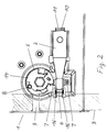
- Figure 2 shows a partial view of the right side of the embodiment from Figure 1 with the bolt 5 and the detent spring 2 inserted in the installation slot 3.
- the housing 1 If the housing 1 is pulled further out of the installation slot, it is in the position shown in FIG. 1.
- the Latch spring 2 protrudes from the housing 1 and is therefore in the locked Position.
- the housing 1 is automatically after complete Insert locked because the detent spring 2 again engages behind the locking edge 4 of the installation slot 3.
- Figure 3 is a partial view of the left side of the housing 1 with a bolt 5 and a detent spring 2 in perspective Representation shown.
- the bolt 5 is rotatable in an opening 12 of the housing 1 stored.
- A is concentric with the axis of rotation of the bolt 5 Hexagon hole 13 provided for engagement of an Allen key.
- On the top 14 of the bolt 5 is the off-center Pin 8 arranged.
- the tongue 11 at the rear end of the detent spring 2 is in the Slot 10 of the housing 1.
- the two stops 7 are arranged opposite one another.
- Figure 4 shows a partial section through the left and right Side of the housing 1, the left latch 5 and the left Latch spring 2 in the unlocked position.
- One stop 7 the detent spring 2 lies on the oblique guide 6 of the bolt 5 on.
- the oblique guide 6 retains the detent spring 2 in the housing 1.
- FIG. 5 shows a side view of the right latch.
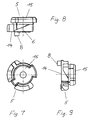
- Figure 7 is a left bolt with its underside 15 of seen below.
- Figure 8 shows the left bolt with the pin 8 on it Top 14, the bottom 15 and the oblique guide 6 am Sheath of the disc-shaped bolt 5.
- Figure 9 shows a further side view of the left latch with the top 14, the pin 8 and the bottom 15.
- a detent spring 2 is shown in perspective.
- the tongue 10 is provided at the rear end of the detent spring 2, which is inserted into the slot 11 in the housing.
- On the front The two stops are located opposite one another at the end of the detent spring 2 7 arranged.
- the front end of the Latching spring 2 has two latching arms 16 directed towards the front.
- the detent springs 2 are symmetrical, so that the left and the right detent spring are identical.
- Figure 11 is a partial view of the right side of the housing shown in perspective without latch and detent spring.
- the housing according to the invention is particularly suitable for a car radio suitable.
- there is a significant advantage of the housing according to the invention in that it is only in the can be installed in the locked position in the installation slot, see above that it is automatically inserted when fully inserted into the slot locked and locked. There are no additional ones Handles required to lock the housing. This ensures that one in the installation slot pushed housing according to the invention is always locked.
Landscapes
- Engineering & Computer Science (AREA)
- Mechanical Engineering (AREA)
- Casings For Electric Apparatus (AREA)
- Glass Compositions (AREA)
- Fittings On The Vehicle Exterior For Carrying Loads, And Devices For Holding Or Mounting Articles (AREA)
Abstract
Description
- Figur 1
- eine Teilansicht der rechten Seite eines erfindungsgemäßen Ausführungsbeispieles des Gehäuses mit einem Riegel und einer Rastfeder in der verriegelten Stellung vor Einschieben in einen Einbauschacht,
- Figur 2
- eine Teilansicht der rechten Seite des Ausführungsbeispieles des Gehäuses aus Figur 1, eingeschoben in den Einbauschacht in der entriegelten Stellung,
- Figur 3
- eine Teilansicht der linken Seite des erfindungsgemäßen Ausführungsbeispieles des Gehäuses mit einem Riegel und einer Rastfeder in perspektivischer Darstellung,
- Figur 4
- einen Teilschnitt durch die linke und rechte Seite des Gehäuses, die Riegel und die Rastfedern in der entriegelten Stellung,
- Figur 5
- eine Seitenansicht eines Ausführungsbeispiels eines rechten Riegels,
- Figur 6
- das Ausführungsbeispiel des rechten Riegels in perspektivischer Darstellung,
- Figur 7
- ein Ausführungsbeispiel eines linken Riegels von unten,
- Figur 8
- eine Seitenansicht des linken Riegels,
- Figur 9
- eine weitere Seitenansicht des linken Riegels,
- Figur 10
- ein Ausführungsbeispiel einer Rastfeder in perspektivischer Darstellung und
- Figur 11
- eine Teilansicht der rechten Seite des Gehäuses ohne Riegel und Rastfeder in perspektivischer Darstellung.
- 1
- Gehäuse
- 2
- Rastfeder
- 3
- Einbauschacht
- 4
- Rastkante
- 5
- Riegel
- 6
- schräge Führung
- 7
- Anschlag
- 8
- Zapfen
- 9
- Führungsschlitz
- 10
- Zunge
- 11
- Schlitz
- 12
- Öffnung
- 13
- Sechskantloch
- 14
- Oberseite des Riegels
- 15
- Unterseite des Riegels
- 16
- Rastarm
- 17
- Aussparung
Claims (12)
- Gehäuse (1), an dessen rechter und linker Seite je eine aus dem Gehäuse (1) ragende Rastfeder (2) angeordnet ist, die zum Einschieben des Gehäuses (1) in einen Einbaurähmen oder in einen Einbauschacht (3) in das Gehäuse versenkbar sind und hinter einer Rastkante (4) des Einbaurahmens oder des Einbauschachtes (3) einrasten,
dadurch gekennzeichnet, daß auf der rechten und linken Seite des Gehäuses (1) je ein drehbarer Riegel (5) mit einer schrägen Führung (6) angeordnet ist, gegen die ein Anschlag (7) der unter Spannung stehenden Rastfeder (2) drückt, daß die Rastfedern (2) durch Drehen der Riegel (5) in die eine Drehrichtug in das Gehäuse (1) versenkbar sind, während sie durch Drehen der Riegel (5) in die andere Drehrichtung freigebbar sind, daß aus jedem Riegel (5) ein außermittig angeordneter Zapfen (8) ragt, für den im Einbaurahmen oder im Einbauschacht (3) ein Führungsschlitz (9) derart angeordnet ist, daß sich das Gehäuse (1) nur in der verriegelten Stellung bei aus dem Gehäuse (1) ragendenden Rastfedern (2) in den Einbaurahmen oder in den Einbauschacht (3) schieben läßt, wobei die Rastfedern (2) beim Einschieben vom Einbaurahmen oder vom Einbauschacht (3) in das Gehäuse (1) gedrückt werden und nach erfolgtem Einschub hinter den Rastkanten (4) einrasten, daß zur Entnahme des Gehäuses (1) aus dem Einbaurahmen oder aus dem Einbauschacht (3) die Rastfedern (2) durch Drehen der Riegel (5) in die entriegelte Stellung gebracht werden, in welcher sie im Gehäuse (1) versenkt sind, daß beim Herausziehen des Gehäuses (1) aus dem Einbaurahmen oder dem Einbauschacht (3) die Zapfen (8) der Riegel (5) an den Einbaurahmen oder an den Einbauschacht (3) stoßen, wodurch die Riegel so weit gedreht werden, bis die Zapfen (8) in die für sie vorgesehenen Führungsschlitze (9) gleiten, wobei gleichzeitig die Rastfedern (2) freigegeben werden, die daher sofort nach Herausziehen aus dem Einbaurahmen oder aus dem Einbauschacht (3) aus dem Gehäuse (1) in die verriegelte Stellung schnappen. - Gehäuse nach Anspruch 1,
dadurch gekennzeichnet, daß am Befestigungsende der Rastfeder (2) eine Zunge (10) vorgesehen ist, die in einen Schlitz (11) des Gehäuses (1) steckbar ist. - Gehäuse nach Anspruch 1 oder 2,
dadurch gekennzeichnet, daß am aus dem Gehäuse (1) ragenden Ende der Rastfeder (2) rechts und links je ein Anschlag (7) vorgesehen ist, der auf der schrägen Führung (6) des Riegels (5) gleitet. - Gehäuse nach Anspruch 1, 2 oder 3,
dadurch gekennzeichnet, daß aus dem aus dem Gehäuse (1) ragenden Ende der Rastfeder (2) zwei Rastarme (16) in Längsrichtung der Rastfeder (2) ragen. - Gehäuse nach Anspruch 1, 2, 3 oder 4,
dadurch gekennzeichnet, daß die Riegel (5) scheibenförmig ausgeführt sind. - Gehäuse nach Anspruch 5,
dadurch gekennzeichnet, daß jeder der beiden Riegel (5) in eine Öffnung (12) des Gehäuses (1) steckbar ist, in welchem er drehbar gelagert ist. - Gehäuse nach Anspruch 5 oder 6,
dadurch gekennzeichnet, daß die schräge Führung (6) für den Anschlag (7) einer Rastfeder (2) am Mantel des Riegels (5) eingearbeitet ist. - Gehäuse nach Anspruch 7,
dadurch gekennzeichnet, daß sich die schräge Führung (6) auf etwa 1/4 Kreissegment erstreckt. - Gehäuse nach einem der vorangehenden Ansprüche,
dadurch gekennzeichnet, daß die Rastfedern (2) durch Rechtsdrehen der Riegel (5) verriegelbar sind, wobei sie aus dem Gehäuse (1) ragen, während sie durch Linksdrehen der Riegel (5) entriegelbar sind, wobei sie im Gehäuse (1) versenkt sind. - Gehäuse nach einem der vorangehenden Ansprüche 1 - 9,
dadurch gekennzeichnet, daß die drehbaren Riegel (5) eine Vorrichtung (13) zum Eingreifen eines üblichen Werkzeugs aufweisen. - Gehäuse nach Anspruch 10,
dadurch gekennzeichnet, daß die drehbaren Riegel (5) einen Schlitz für den Eingriff eines Schraubendrehers, eine Ausnehmung für den Eingriff eines Torques-Schraubendrehers, einen Sechskantkopf für den Eingriff eines Schraubenschlüssels oder ein Sechskantloch (13) für den Eingriff eines Inbusschlüssels aufweisen. - Gehäuse nach einem der vorangehenden Ansprüche,
dadurch gekennzeichnet, daß es sich bei dem Gehäuse (1) um das Gehäuse eines Autoradios handelt.
Applications Claiming Priority (2)
| Application Number | Priority Date | Filing Date | Title |
|---|---|---|---|
| DE10120109 | 2001-04-25 | ||
| DE10120109A DE10120109C1 (de) | 2001-04-25 | 2001-04-25 | Gehäuse |
Publications (3)
| Publication Number | Publication Date |
|---|---|
| EP1253046A2 true EP1253046A2 (de) | 2002-10-30 |
| EP1253046A3 EP1253046A3 (de) | 2004-05-19 |
| EP1253046B1 EP1253046B1 (de) | 2005-05-25 |
Family
ID=7682573
Family Applications (1)
| Application Number | Title | Priority Date | Filing Date |
|---|---|---|---|
| EP02006065A Expired - Lifetime EP1253046B1 (de) | 2001-04-25 | 2002-03-18 | Gehäuse |
Country Status (4)
| Country | Link |
|---|---|
| US (1) | US7123885B2 (de) |
| EP (1) | EP1253046B1 (de) |
| AT (1) | ATE296219T1 (de) |
| DE (2) | DE10120109C1 (de) |
Families Citing this family (3)
| Publication number | Priority date | Publication date | Assignee | Title |
|---|---|---|---|---|
| KR100651497B1 (ko) * | 2005-08-22 | 2006-11-29 | 삼성전자주식회사 | 휴대용 단말기의 힌지 장치 |
| JP6563354B2 (ja) * | 2016-03-09 | 2019-08-21 | アルパイン株式会社 | 電子機器 |
| CN112179387B (zh) * | 2019-07-01 | 2022-05-13 | 长城汽车股份有限公司 | 安装结构 |
Citations (3)
| Publication number | Priority date | Publication date | Assignee | Title |
|---|---|---|---|---|
| DE3015259A1 (de) | 1980-04-21 | 1981-10-29 | Siemens AG, 1000 Berlin und 8000 München | Schaltschrank |
| DE9206965U1 (de) | 1992-05-22 | 1992-08-13 | Blaupunkt-Werke Gmbh, 3200 Hildesheim | Autoradio mit einer Befestigungsvorrichtung |
| DE19614781A1 (de) | 1996-04-04 | 1997-10-09 | Becker Gmbh | Befestigungssystem für Autoradios |
Family Cites Families (12)
| Publication number | Priority date | Publication date | Assignee | Title |
|---|---|---|---|---|
| DE1221322B (de) * | 1962-10-25 | 1966-07-21 | Nordmende | Halterungseinrichtung fuer ein Rundfunkgeraet mit Koffergehaeuse zur Anbringung in Kraftfahrzeugen |
| CH668583A5 (it) * | 1986-06-19 | 1989-01-13 | Roadstar Sa | Dispositivo di installazione di autoradio, lettori di cassette o altri apparecchi similari su veicoli mobili o barche. |
| JPH048644A (ja) * | 1990-04-25 | 1992-01-13 | Pioneer Electron Corp | 車載用機器の取付け装置 |
| US5339362A (en) * | 1992-01-07 | 1994-08-16 | Rockford Corporation | Automotive audio system |
| US5438685A (en) * | 1993-11-26 | 1995-08-01 | Motorola, Inc. | Vehicular adapter pocket and handle assembly |
| JP3571851B2 (ja) * | 1996-05-17 | 2004-09-29 | パイオニア株式会社 | 車載用携帯電話機の取付機構 |
| US6339699B1 (en) * | 1997-09-24 | 2002-01-15 | Harness System Technologies Research, Ltd. | Phone holder |
| DE19825091C2 (de) * | 1998-06-05 | 2000-09-21 | Becker Gmbh | Rundfunkempfänger |
| JP3265572B2 (ja) * | 1998-11-20 | 2002-03-11 | 日本電気株式会社 | 折畳式携帯電話器の開閉装置 |
| US6745603B1 (en) * | 2001-02-22 | 2004-06-08 | Barry Shaw | Electromagnetic integrative door locking device and method of installation |
| US6742822B2 (en) * | 2001-02-27 | 2004-06-01 | Mark Willard Vejnar | Auxiliary tailgate and retractable stop |
| US6655736B1 (en) * | 2001-12-03 | 2003-12-02 | George Gabriel Arenas | Retractable seat protection cover |
-
2001
- 2001-04-25 DE DE10120109A patent/DE10120109C1/de not_active Expired - Lifetime
-
2002
- 2002-03-18 DE DE50203173T patent/DE50203173D1/de not_active Expired - Lifetime
- 2002-03-18 EP EP02006065A patent/EP1253046B1/de not_active Expired - Lifetime
- 2002-03-18 AT AT02006065T patent/ATE296219T1/de not_active IP Right Cessation
- 2002-04-25 US US10/132,074 patent/US7123885B2/en not_active Expired - Lifetime
Patent Citations (3)
| Publication number | Priority date | Publication date | Assignee | Title |
|---|---|---|---|---|
| DE3015259A1 (de) | 1980-04-21 | 1981-10-29 | Siemens AG, 1000 Berlin und 8000 München | Schaltschrank |
| DE9206965U1 (de) | 1992-05-22 | 1992-08-13 | Blaupunkt-Werke Gmbh, 3200 Hildesheim | Autoradio mit einer Befestigungsvorrichtung |
| DE19614781A1 (de) | 1996-04-04 | 1997-10-09 | Becker Gmbh | Befestigungssystem für Autoradios |
Also Published As
| Publication number | Publication date |
|---|---|
| EP1253046B1 (de) | 2005-05-25 |
| ATE296219T1 (de) | 2005-06-15 |
| EP1253046A3 (de) | 2004-05-19 |
| DE10120109C1 (de) | 2002-06-27 |
| US7123885B2 (en) | 2006-10-17 |
| US20020173280A1 (en) | 2002-11-21 |
| DE50203173D1 (de) | 2005-06-30 |
Similar Documents
| Publication | Publication Date | Title |
|---|---|---|
| DE2903176C2 (de) | Einbaueinrichtung für Zusatzgeräte in vorgegebenen Einbauöffnungen | |
| DE4230820C2 (de) | Schnappschloß | |
| DE102014104854B4 (de) | Kippverhinderungsbaugruppe für eine Reihe von Schubladen in einem Werkzeugschrank | |
| DE69710140T2 (de) | Türschloss eines fahrzeuges | |
| DE20100847U1 (de) | Chipbetätigtes elektronisches Schloß | |
| DE8915994U1 (de) | Kraftfahrzeugtürverschluß mit einem Zentralverriegelungsantrieb | |
| DE69611719T2 (de) | Vorrichtung zur Führung, zum Antrieb und zur Verriegelung eines elektrischen oder elektronischen Ausrüstungseinschubs in einem Schrank | |
| EP3472414B1 (de) | Kraftfahrzeug-griffanordnung | |
| DE69432085T2 (de) | Sicherheitsvorrichtung gegen den diebstahl von computern | |
| DE3502485C2 (de) | ||
| DE202011102905U1 (de) | Schloss | |
| DE4100449A1 (de) | Verriegelungsvorrichtung fuer in fahrzeuge einbaubare elektronische geraete | |
| DE29606075U1 (de) | Kombinationsschloßvorrichtung | |
| WO2002038894A1 (de) | Hebelverschluss | |
| EP1253046B1 (de) | Gehäuse | |
| DE2723887B2 (de) | Befestigungsvorrichtung für Schließzylinder | |
| EP0143332B1 (de) | Schnellentriegelungsvorrichtung für eine verriegelte Tür | |
| DE10246439B4 (de) | Gehäuse mit diebstahlsicherer Batterie-Lagerung | |
| EP3179021A1 (de) | Türgriffanordnung für ein kraftfahrzeug | |
| DE4243726C2 (de) | Vorrichtung zur Verriegelung einer Bedieneinheit mit einem in ein Fahrzeug eingebauten elektronischen Gerät | |
| DE202015002795U1 (de) | Verriegelungsvorrichtung einer Steckbaugruppe | |
| DE102024100958A1 (de) | Schloss | |
| DE2811861C3 (de) | Feststeller für den schwenkbaren Flügel einer Fahrzeugtür | |
| DE69715129T2 (de) | Handhabe mit vereinfachter Sicherheitsbetätigung für Lastwagentüre, Anhängertüre oder ähnliches | |
| DE4405346C2 (de) | Vorrichtung zur Entriegelung und Verriegelung der Rücksitzlehne von Kfz |
Legal Events
| Date | Code | Title | Description |
|---|---|---|---|
| PUAI | Public reference made under article 153(3) epc to a published international application that has entered the european phase |
Free format text: ORIGINAL CODE: 0009012 |
|
| AK | Designated contracting states |
Kind code of ref document: A2 Designated state(s): AT BE CH CY DE DK ES FI FR GB GR IE IT LI LU MC NL PT SE TR |
|
| AX | Request for extension of the european patent |
Free format text: AL;LT;LV;MK;RO;SI |
|
| PUAL | Search report despatched |
Free format text: ORIGINAL CODE: 0009013 |
|
| AK | Designated contracting states |
Kind code of ref document: A3 Designated state(s): AT BE CH CY DE DK ES FI FR GB GR IE IT LI LU MC NL PT SE TR |
|
| AX | Request for extension of the european patent |
Extension state: AL LT LV MK RO SI |
|
| 17P | Request for examination filed |
Effective date: 20040527 |
|
| GRAP | Despatch of communication of intention to grant a patent |
Free format text: ORIGINAL CODE: EPIDOSNIGR1 |
|
| GRAS | Grant fee paid |
Free format text: ORIGINAL CODE: EPIDOSNIGR3 |
|
| RAP1 | Party data changed (applicant data changed or rights of an application transferred) |
Owner name: HARMAN BECKER AUTOMOTIVE SYSTEMS GMBH |
|
| AKX | Designation fees paid |
Designated state(s): AT BE CH CY DE DK ES FI FR GB GR IE IT LI LU MC NL PT SE TR |
|
| GRAA | (expected) grant |
Free format text: ORIGINAL CODE: 0009210 |
|
| AK | Designated contracting states |
Kind code of ref document: B1 Designated state(s): AT BE CH CY DE DK ES FI FR GB GR IE IT LI LU MC NL PT SE TR |
|
| PG25 | Lapsed in a contracting state [announced via postgrant information from national office to epo] |
Ref country code: IE Free format text: LAPSE BECAUSE OF FAILURE TO SUBMIT A TRANSLATION OF THE DESCRIPTION OR TO PAY THE FEE WITHIN THE PRESCRIBED TIME-LIMIT Effective date: 20050525 Ref country code: NL Free format text: LAPSE BECAUSE OF FAILURE TO SUBMIT A TRANSLATION OF THE DESCRIPTION OR TO PAY THE FEE WITHIN THE PRESCRIBED TIME-LIMIT Effective date: 20050525 Ref country code: FI Free format text: LAPSE BECAUSE OF FAILURE TO SUBMIT A TRANSLATION OF THE DESCRIPTION OR TO PAY THE FEE WITHIN THE PRESCRIBED TIME-LIMIT Effective date: 20050525 Ref country code: TR Free format text: LAPSE BECAUSE OF FAILURE TO SUBMIT A TRANSLATION OF THE DESCRIPTION OR TO PAY THE FEE WITHIN THE PRESCRIBED TIME-LIMIT Effective date: 20050525 |
|
| REG | Reference to a national code |
Ref country code: GB Ref legal event code: FG4D Free format text: NOT ENGLISH |
|
| REG | Reference to a national code |
Ref country code: CH Ref legal event code: EP |
|
| REG | Reference to a national code |
Ref country code: IE Ref legal event code: FG4D Free format text: LANGUAGE OF EP DOCUMENT: GERMAN |
|
| REF | Corresponds to: |
Ref document number: 50203173 Country of ref document: DE Date of ref document: 20050630 Kind code of ref document: P |
|
| PG25 | Lapsed in a contracting state [announced via postgrant information from national office to epo] |
Ref country code: SE Free format text: LAPSE BECAUSE OF FAILURE TO SUBMIT A TRANSLATION OF THE DESCRIPTION OR TO PAY THE FEE WITHIN THE PRESCRIBED TIME-LIMIT Effective date: 20050825 Ref country code: GR Free format text: LAPSE BECAUSE OF FAILURE TO SUBMIT A TRANSLATION OF THE DESCRIPTION OR TO PAY THE FEE WITHIN THE PRESCRIBED TIME-LIMIT Effective date: 20050825 Ref country code: DK Free format text: LAPSE BECAUSE OF FAILURE TO SUBMIT A TRANSLATION OF THE DESCRIPTION OR TO PAY THE FEE WITHIN THE PRESCRIBED TIME-LIMIT Effective date: 20050825 |
|
| PG25 | Lapsed in a contracting state [announced via postgrant information from national office to epo] |
Ref country code: ES Free format text: LAPSE BECAUSE OF FAILURE TO SUBMIT A TRANSLATION OF THE DESCRIPTION OR TO PAY THE FEE WITHIN THE PRESCRIBED TIME-LIMIT Effective date: 20050905 |
|
| GBT | Gb: translation of ep patent filed (gb section 77(6)(a)/1977) |
Effective date: 20050929 |
|
| PG25 | Lapsed in a contracting state [announced via postgrant information from national office to epo] |
Ref country code: PT Free format text: LAPSE BECAUSE OF FAILURE TO SUBMIT A TRANSLATION OF THE DESCRIPTION OR TO PAY THE FEE WITHIN THE PRESCRIBED TIME-LIMIT Effective date: 20051027 |
|
| NLV1 | Nl: lapsed or annulled due to failure to fulfill the requirements of art. 29p and 29m of the patents act | ||
| REG | Reference to a national code |
Ref country code: IE Ref legal event code: FD4D |
|
| PG25 | Lapsed in a contracting state [announced via postgrant information from national office to epo] |
Ref country code: AT Free format text: LAPSE BECAUSE OF NON-PAYMENT OF DUE FEES Effective date: 20060318 |
|
| ET | Fr: translation filed | ||
| PG25 | Lapsed in a contracting state [announced via postgrant information from national office to epo] |
Ref country code: LU Free format text: LAPSE BECAUSE OF NON-PAYMENT OF DUE FEES Effective date: 20060331 Ref country code: CH Free format text: LAPSE BECAUSE OF NON-PAYMENT OF DUE FEES Effective date: 20060331 Ref country code: BE Free format text: LAPSE BECAUSE OF NON-PAYMENT OF DUE FEES Effective date: 20060331 Ref country code: MC Free format text: LAPSE BECAUSE OF NON-PAYMENT OF DUE FEES Effective date: 20060331 Ref country code: LI Free format text: LAPSE BECAUSE OF NON-PAYMENT OF DUE FEES Effective date: 20060331 |
|
| PLBE | No opposition filed within time limit |
Free format text: ORIGINAL CODE: 0009261 |
|
| STAA | Information on the status of an ep patent application or granted ep patent |
Free format text: STATUS: NO OPPOSITION FILED WITHIN TIME LIMIT |
|
| 26N | No opposition filed |
Effective date: 20060228 |
|
| REG | Reference to a national code |
Ref country code: CH Ref legal event code: PL |
|
| BERE | Be: lapsed |
Owner name: HARMAN BECKER AUTOMOTIVE SYSTEMS G.M.B.H. Effective date: 20060331 |
|
| PG25 | Lapsed in a contracting state [announced via postgrant information from national office to epo] |
Ref country code: CY Free format text: LAPSE BECAUSE OF FAILURE TO SUBMIT A TRANSLATION OF THE DESCRIPTION OR TO PAY THE FEE WITHIN THE PRESCRIBED TIME-LIMIT Effective date: 20050525 |
|
| REG | Reference to a national code |
Ref country code: FR Ref legal event code: PLFP Year of fee payment: 15 |
|
| PGFP | Annual fee paid to national office [announced via postgrant information from national office to epo] |
Ref country code: FR Payment date: 20160328 Year of fee payment: 15 Ref country code: GB Payment date: 20160329 Year of fee payment: 15 |
|
| PGFP | Annual fee paid to national office [announced via postgrant information from national office to epo] |
Ref country code: IT Payment date: 20160323 Year of fee payment: 15 |
|
| GBPC | Gb: european patent ceased through non-payment of renewal fee |
Effective date: 20170318 |
|
| REG | Reference to a national code |
Ref country code: FR Ref legal event code: ST Effective date: 20171130 |
|
| PG25 | Lapsed in a contracting state [announced via postgrant information from national office to epo] |
Ref country code: FR Free format text: LAPSE BECAUSE OF NON-PAYMENT OF DUE FEES Effective date: 20170331 |
|
| PG25 | Lapsed in a contracting state [announced via postgrant information from national office to epo] |
Ref country code: IT Free format text: LAPSE BECAUSE OF NON-PAYMENT OF DUE FEES Effective date: 20170318 Ref country code: GB Free format text: LAPSE BECAUSE OF NON-PAYMENT OF DUE FEES Effective date: 20170318 |
|
| PGFP | Annual fee paid to national office [announced via postgrant information from national office to epo] |
Ref country code: DE Payment date: 20210217 Year of fee payment: 20 |
|
| REG | Reference to a national code |
Ref country code: DE Ref legal event code: R071 Ref document number: 50203173 Country of ref document: DE |