EP1251702A2 - Videokodierung und -dekodierung - Google Patents
Videokodierung und -dekodierung Download PDFInfo
- Publication number
- EP1251702A2 EP1251702A2 EP20020252694 EP02252694A EP1251702A2 EP 1251702 A2 EP1251702 A2 EP 1251702A2 EP 20020252694 EP20020252694 EP 20020252694 EP 02252694 A EP02252694 A EP 02252694A EP 1251702 A2 EP1251702 A2 EP 1251702A2
- Authority
- EP
- European Patent Office
- Prior art keywords
- video
- memory
- regions
- processing method
- memory regions
- Prior art date
- Legal status (The legal status is an assumption and is not a legal conclusion. Google has not performed a legal analysis and makes no representation as to the accuracy of the status listed.)
- Withdrawn
Links
Images


Classifications
-
- G—PHYSICS
- G06—COMPUTING OR CALCULATING; COUNTING
- G06T—IMAGE DATA PROCESSING OR GENERATION, IN GENERAL
- G06T1/00—General purpose image data processing
-
- H—ELECTRICITY
- H04—ELECTRIC COMMUNICATION TECHNIQUE
- H04N—PICTORIAL COMMUNICATION, e.g. TELEVISION
- H04N19/00—Methods or arrangements for coding, decoding, compressing or decompressing digital video signals
- H04N19/85—Methods or arrangements for coding, decoding, compressing or decompressing digital video signals using pre-processing or post-processing specially adapted for video compression
-
- H—ELECTRICITY
- H04—ELECTRIC COMMUNICATION TECHNIQUE
- H04N—PICTORIAL COMMUNICATION, e.g. TELEVISION
- H04N19/00—Methods or arrangements for coding, decoding, compressing or decompressing digital video signals
- H04N19/10—Methods or arrangements for coding, decoding, compressing or decompressing digital video signals using adaptive coding
- H04N19/169—Methods or arrangements for coding, decoding, compressing or decompressing digital video signals using adaptive coding characterised by the coding unit, i.e. the structural portion or semantic portion of the video signal being the object or the subject of the adaptive coding
- H04N19/186—Methods or arrangements for coding, decoding, compressing or decompressing digital video signals using adaptive coding characterised by the coding unit, i.e. the structural portion or semantic portion of the video signal being the object or the subject of the adaptive coding the unit being a colour or a chrominance component
-
- H—ELECTRICITY
- H04—ELECTRIC COMMUNICATION TECHNIQUE
- H04N—PICTORIAL COMMUNICATION, e.g. TELEVISION
- H04N19/00—Methods or arrangements for coding, decoding, compressing or decompressing digital video signals
- H04N19/42—Methods or arrangements for coding, decoding, compressing or decompressing digital video signals characterised by implementation details or hardware specially adapted for video compression or decompression, e.g. dedicated software implementation
- H04N19/423—Methods or arrangements for coding, decoding, compressing or decompressing digital video signals characterised by implementation details or hardware specially adapted for video compression or decompression, e.g. dedicated software implementation characterised by memory arrangements
-
- H—ELECTRICITY
- H04—ELECTRIC COMMUNICATION TECHNIQUE
- H04N—PICTORIAL COMMUNICATION, e.g. TELEVISION
- H04N19/00—Methods or arrangements for coding, decoding, compressing or decompressing digital video signals
- H04N19/60—Methods or arrangements for coding, decoding, compressing or decompressing digital video signals using transform coding
- H04N19/61—Methods or arrangements for coding, decoding, compressing or decompressing digital video signals using transform coding in combination with predictive coding
-
- H—ELECTRICITY
- H04—ELECTRIC COMMUNICATION TECHNIQUE
- H04N—PICTORIAL COMMUNICATION, e.g. TELEVISION
- H04N5/00—Details of television systems
- H04N5/222—Studio circuitry; Studio devices; Studio equipment
- H04N5/262—Studio circuits, e.g. for mixing, switching-over, change of character of image, other special effects ; Cameras specially adapted for the electronic generation of special effects
Definitions
- the present invention relates to:-
- video data input to a camera is stored in a memory in response to a capture command for encoding the video data. Since display devices typically process a maximum 30 frames per second, it takes a minimum of 33 milliseconds (ms) to process one frame.
- a hardware unit generates a vertical synchronizing (Vsync) signal for indicating the possibility of capture every 33 ms, and a software unit causes the sending of a capture command and a memory address to the hardware unit whenever the Vsync is generated. Subsequently, the hardware unit stores the video data captured in response to the capture command in the memory.
- Vsync vertical synchronizing
- video data that is decoded by a software-implemented decoder is typically stored in a predetermined region of a memory and displayed on a display device such as a liquid crystal display (LCD).
- a display device such as a liquid crystal display (LCD).
- the software unit causes the sending of updated information and regions of the updated memory to the display device.
- two or more memories are usually used to store the video data during encoding and decoding processes, and the memory is referred to as a ping-pong memory.
- a software unit (b) for encoding checks the state of a hardware unit (a) for camera capture and waits for a vertical synchronizing (Vsync) signal after encoding data of a frame (see intervals 110 and 120), and then, if the software unit (b) receives the Vsync signal from the hardware unit (a), a capture command for data of frames 1 and 2 is transmitted.
- Vsync vertical synchronizing
- a vertical synchronization signal (a) generates an interrupt 220 immediately when software unit (b) requires data, stops routine operations of the software unit (b) for a short time, and forcibly causes the software unit (b) to transmit information required for capturing data of frame 1 to the hardware unit.
- the software unit (b) performs an interrupt service routine (ISR).
- ISR interrupt service routine
- the software unit receives an interrupt signal 220 while encoding frame 2 (see interval 210 of (c)), the software unit stops encoding for a short time (see interval 212 of (c)), transmits information required for capturing data of frame 1 to the hardware unit, and then restarts encoding frame 2. If another interrupt signal 221 is received even though encoding of frame 2 is not complete, the software unit does not give a capture command for frame 2 but escapes from the ISR and performs encoding of frame 2 continuously.
- the software unit receives an interrupt signal 220 while decoding frame 2 (see interval 210 of (c))
- the software unit stops decoding frame 2 for a short time (see interval 212 of (c)), transmits information required for reading the data of frame 1 to the hardware unit (a), and then restarts decoding of frame 2. If another interrupt is received even though decoding of frame 2 is not complete, the software unit does not give a read command for frame 2 but escapes from the ISR and performs decoding of frame 2 continuously.
- the interrupt method if an interrupt is generated, encoding and decoding are immediately performed without waiting for a Vsync signal, and thus, the interrupt method is faster than the polling method.
- interrupts are generated frequently, pipelining cannot be used in a reduced instruction set computer (RISC) processor, and thus overall speed is decreased.
- RISC reduced instruction set computer
- any one given type of interrupt for one particular purpose is not used frequently in a system
- various types of interrupts are used together in the system.
- Various types of interrupts for example, an interrupt for a camera, an interrupt for an LCD, an interrupt for a LAN, and an interrupt for a universal asynchronous receiver/transmitter (UART) port, are used together in the system, and the camera and the LCD generate an interrupt every 33 ms.
- UART universal asynchronous receiver/transmitter
- the decoding time of software unit is not fixed, and thus, video data is processed unstably. That is, in a case where all available memory regions are used even though the decoding time of consecutive frames is so short that all image data are not displayed on a display device, video data decoded after that must be discarded. This causes the video to appear jerky or resources of an encoder or decoder to be used unnecessarily.
- a video encoding method is characterised in that the video encoding process is performed substantially continuously, an index identifying the currently used memory region is updated in dependence on a frame synchronising signal associated with the video frames being stored in said memory regions and, at the end of each performance of said encoding process, one of said memory regions is selected to provide data for the next performance of said encoding process in dependence on the current value of said index.
- a video encoding apparatus is characterised in that the encoding means is configured such that the video encoding process is performed substantially continuously, the video storing means is configured to update an index, identifying the currently used memory region, in dependence on a frame synchronising signal associated with the video frames being stored in said memory regions and the encoding means is configured such that, at the end of each performance of said encoding process, one of said memory regions is selected to provide data for the next performance of said encoding process in dependence on the current value of said index.
- the present invention provides a video encoding apparatus and method which are capable of stable operation at a high speed with a small amount of memory.
- a video decoding method is characterised in that an index identifying the memory region into which an encoded video frame is being written is updated in dependence on said frame synchronising signal and, after each performance of said decoding process, one of said memory regions is selected to provide data for the next performance of said decoding process in dependence on the current value of said index, the decoding process being held off, if the index has not changed since the start of the last performance of the decoding process.
- An video decoding apparatus is characterised in that the video storing means is configured to update an index, identifying the memory region into which an encoded video frame is currently being written, in dependence on said frame synchronising signal, and the decoding means is configured such that, after each performance of said decoding process, one of said memory regions is selected to provide data for the next performance of said decoding process in dependence on the current value of said index, the decoding process being held off, if the index has not changed since the start of the last performance of the decoding process.
- the present invention provides a video decoding apparatus and method which are capable of stable operation at a high speed with a small amount of memory.
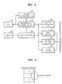
- a central processing unit (CPU) 310 executes software.
- the software controls the operation of a hardware unit (not shown) by a register file.
- a system controlling unit 320 transmits a control command of the central processing unit (CPU) 310 to the hardware unit. If the CPU 310 writes operation data into a register file (not shown), the system controlling unit 320 interprets the operation data, thereby performing a command of the software unit according to a predetermined protocol.
- CPU central processing unit
- a register file controlling unit 330 controls the register file which is received from the CPU 310 in response to a control command of the system controlling unit 320 and the stipulated protocol. Also, the register file controlling unit 330 controls the register file according to a vertical synchronizing (Vsync) signal and interprets each bit of the register file.
- Vsync vertical synchronizing
- a buffer controlling unit 340 buffers data, which is input at fixed times separated by a predetermined interval, in a buffer such as a synchronous dynamic random access memory (SDRAM).
- SDRAM synchronous dynamic random access memory
- a camera 350 outputs video data, vertical synchronizing (Vsync) and horizontal synchronizing (Hsync) signals to a pre-processor 360.
- the pre-processor 360 converts input 4:2:2 video data into 4:2:0 video data. That is, the pre-processor 360 subsamples the video data in a vertical direction.
- First, second, and third buffers 370, 380, 390 store a signal Y, a signal C b , and a signal C r , which are input from the pre-processor 360, respectively.
- the buffer size can be varied according to the structure of the system.
- a hardware unit divides a memory into a plurality of memory pages during initializing, sets an address for each memory page and stores video in the memory pages automatically according to a predetermined order when a capture command is received from the software unit.
- the memory pages are numbered 0 to 2 on the basis of their capture order, but may be increased in the case of parallel processing or applications.
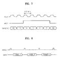
- (a) is a timing diagram of a V_sync signal or a frame synchronizing signal that is generated from hardware unit, and a memory page (MP) is cycled in the order of "0 ⁇ 1 ⁇ 2 ⁇ 0 ... " in response to the V_sync signal.
- the MP is a memory region in which the captured data are stored for one V_sync signal cycle while a camera begins capturing and finishes capturing.
- the hardware unit operates as a slave of the software unit for memory control and checks via a register whether an image has been captured.
- (b) is a timing diagram illustrating control performed in by software unit.
- the software unit reads a memory page and gives a capture command.
- Software unit count value sw_cnt representing a memory page to be encoded, is calculated using (MP+2) modulo 3 after the memory page is read in response to a V_sync signal, and is updated in the order of "0 ⁇ 1 ⁇ 1 ⁇ 2 ... ".
- (c) is a timing diagram illustrating encoding performed by software unit.
- the software unit controls a hardware unit to encode data stored in a memory page of (MP+2) modulo 3 in accordance with a calculated value of the software unit counter. If the memory page read by the software unit is being captured, an identical frame is re-encoded (fr. 1 encoding), and if not, the captured memory page is encoded (fr. 0 encoding and fr. 2 encoding).
- step 610 the hardware unit of the system is initialized and then, in step 620, the hardware unit begins encoding.
- a software unit reads a memory page (MP).
- step 640 the software unit checks the memory page (MP) and gives a capture command to the MP.
- step 650 the software unit calculates a memory page sw_cnt to be encoded using (MP+2) modulo 3.
- step 660 the software unit encodes the calculated memory page sw_cnt.
- step 670 it is determined whether encoding is complete, and if encoding is complete, pre-processing is ended. If not, the software unit performs pre-processing by reading the memory page again.
- the number of regions of memory required is increased. For example, if the number to be parallel processed is N p , the number of a required memory page (MP) is (N p +2). In such a case, if the number of parallel processes is two of ME/MC and DCT, four memory pages (MPs) are required, and a memory page to be encoded is numbered (MP+3) modulo 4.
- the CPU 310 supports encoding in units of frames.
- Y, C b , and C r which are input to a camera, support a capture function in units of frames.
- the input video data is input in units of frames in synchronism with vertical synchronizing signal.
- the camera is a CCIR 601 format apparatus and a QCIF (176 x 144) progressive scan method is used.
- the input video data is 8-bit Y, U, and V data, and a 13.5 MHz clock signal PCLK is input to the system, and 8-bit data DATA[7:0] is output in response to a synchronized clock signal.
- input video data DATA can be input at a maximum rate of 60 frames per second. Processing of the video data DATA depends on the capacity of an encoder.
- the hardware unit operates as a slave of the CPU 310 and selects an frame for encoding. Since the frames of the input data are delimited by an input vertical synchronizing signal VSYNC, the hardware unit selects data to be encoded in response to the VSYNC.
- video data is input from a camera in response to vertical synchronizing signal v_sync and is captured as required by the CPU 310.
- the CPU 310 captures the video data using a register file.
- a capture command is transmitted to the register file using a status register. If a state bit state[31] is set to "1", the video data is captured.
- Other set bits in the status register represent the index numbers 0, 1, and 2 of three memories which are being used in the hardware unit, as shown in Figure 4.
- the CPU 310 reads the memory number and causes the sending of a memory region to be processed to the software unit.
- an internal register read signal internal reg_rd in the hardware unit is set to "1".
- the internal register read signal internal reg_rd is changed into "0". If the internal register read signal internal reg_rd is set to "0" and simultaneously capture bits are set in the status register, the video data is captured. Subsequently, if the capture bits are not set in the status register at the next vertical synchronizing signal v_sync, capture is enabled. As a result, the capture bits of the status register are checked at each vertical synchronizing signal v_sync.
- the starting address of the set memory is stored in the CPU 310 after booting, and the value of the starting address is effective until the set address value varies.
- the CPU 310 generates the starting address in units of the v_sync through a register.
- the number of memory regions H/W cnt is cycled in the order of "0 ⁇ 1 ⁇ 2 ⁇ 0 " if the data are captured for each v_sync.
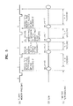
- data decoded in a source codec unit (not shown) is stored in a Y buffer 1020, a C b buffer 1022, a C r buffer 1024, in the order Y, C b , and C r , and is transmitted to a post-processor 1050 in response to vertical and horizontal synchronizing signals generated in a display unit 1070.
- the post-processor 1050 converts 4:2:0 data into 4:2:2 data, converts the 4:2:2 format video data into 4:4:4 format RGB data and transmits the RGB data to the display unit 1070.
- the post-processor 1050 accesses OSD data stored in an OSD buffer 1026, using a direct memory access (DMA) controller (not shown).
- DMA direct memory access
- a system controlling unit 1040 transmits a control command of the central processing unit (CPU) 1060 to the hardware unit. If the CPU 1060 writes operation data into the register file and orders an operation for a hardware unit, the system controlling unit 1040 interprets the operation, thereby performing a command of the software unit according to each hardware unit and a predetermined protocol.
- CPU central processing unit
- the CPU 1060 transmits a display command through a register to control the hardware unit.
- a DMA register 1030 performs an operation according to data that is received from the register of the CPU 1060 in response to the control command of the system controlling unit 1040 and the predetermined protocol.
- a hardware unit divides a memory page (MP) into a plurality of smaller memory pages during initialization, sets an address in each memory page and stores automatically displayed video according to a predetermined order, if a display command is received from software unit.
- the memory pages are numbered 0 to 2 on the basis of a capture order, but may be increased if parallel processing or applications are used.
- (a) is a timing diagram of a vertical synchronizing signal V_sync or a frame synchronizing signal, which is generated from a hardware unit, a memory page (MP) is updated in the order of "2 ⁇ 0 ⁇ 1 ⁇ 2 ⁇ 0 ... " in response to the V_sync.
- the MP is a ping-pong memory region that is displayed for one V_sync period while a liquid crystal display (LCD) begins displaying and finishes displaying.
- the hardware unit operates as a slave of the software unit for memory control and checks via a register whether an image is being displayed.
- (b) is a timing diagram illustrating control performed in the software unit.
- the software unit reads the memory page displayed as shown in (a) and gives a display command.
- (c) is a timing diagram illustrating decoding performed by software unit.
- the software unit controls a hardware unit to decode a memory page corresponding to the software unit count value sw_cnt. That is, if the software unit determines that the displaying memory page is the same as the memory page to be decoded, the software unit waits without decoding. If not, the software unit decodes the corresponding memory page (fr. 0, fr. 1, fr. 2 decoding).
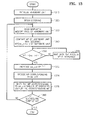
- step 1310 a hardware unit of a system is initialized, and then, in step 1320, the hardware unit begins decoding.
- a software unit reads a displayed memory page (MP) from the hardware unit.
- MP displayed memory page
- the software unit compares the value of the displayed memory page (MP) with an increased software unit count value sw_cnt+1.
- step 1360 the software unit waits without decoding until the displaying memory page (MP) is increased.
- step 1372 if the memory page (MP) is not the same as that indexed by the increased software unit count value sw_cnt+1, the software unit count value sw_cnt is increased by "1", and in step 1374, the memory page corresponding to the count value sw_cnt is decided.
- step 1376 when the memory page corresponding to the software unit count value sw_cnt should be displayed, the corresponding memory page is displayed. Data from the memory page is displayed for one synchronizing signal cycle when at least two or more requests for display are made.
- step 1380 it is determined whether decoding is completed, and if decoding is completed, post-processing is ended. If not, the software unit performs post-processing by reading the memory page again.
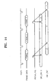
- FIG 14 is a timing diagram illustrating control of the memory of Figure 11
- data read from a bus is stored in a region of the number (N) of memories for post processing.
- the software unit selects a memory region in which decoded video data is to be stored.
- the CPU 1060 monitors the state of the memory that is being read. In the case where the software unit updates the data in the memory region that is being displayed, an image division phenomenon occurs.
- Post-processing is performed in response to a vertical synchronizing signal (Vsync) like pre-processing. Since there is no timing information in the software unit, the software unit selects the number (N) of memory region to be used when the data is stored in the memory the moment decoding is complete.
- the software unit reads the status register to determine the memory region and transmits information about the memory region to be displayed on the hardware unit via the register data. Predetermined status register bits are used as the register data. This means that the region for the display data is identified by a number, and the number is transmitted to the CPU 1060. The number is effective when the next updating of data due is not performed after the initial starting address of a number (N) of frames is set after booting.
- the CPU 1060 generates the starting address in units of vertical synchronizing signals (Vsync). A Y1 starting address, a Y2 starting address, and a Y3 starting address are mapped as 0, 1, and 2 in the memory region of Figure 11.
- the CPU 1060 counts two values corresponding to a software unit count value sw_cnt, and a hardware count value hw_cnt using two bits of a status register status_reg. If decoding is complete, the software unit reads the hardware count value hw_cnt. Here, the software unit transmits numbers, which are not used in the hardware count value hw_cnt, to the hardware unit sequentially. The hardware unit increases the numbers linearly and transmits the numbers to the software unit. If the hardware unit cannot receive a count value from the software unit, data is read from the previous address, thereby causing an image holding phenomenon.
- the software unit can decode two frames within an interval between vertical synchronizing signals (Vsync). First, the difference between the software unit count value sw_cnt and the hardware unit count value hw_cnt is maintained at two. If two frames are decoded in a Vsync interval, the difference between the two count values is decreased by one.
- Vsync vertical synchronizing signals
- N b There is a number (N b ) of memory pages of a buffer in the present invention, and time required for decoding is delayed by one frame whenever the memory page of a buffer is increased by one.
- N b a number of redundant buffers
- N b + 3 a total number of memory pages
- N b must be consistent between a decoder and a display device.
- Three memory pages are included in Figure 11, but the number of the memory pages may be increased according to the number of buffers.
- a decoder In the case of a decoder, display of a maximum number (1+N b ) of memory pages can be requested within a V_sync period. If the number (N b ) of memory pages (MPs) for a buffer is in a full state, only one display may be requested for a V_sync period. If the decoder cannot immediately request a driving unit to display data from the memory pages, decoding is delayed until the request is possible. The state of all display driving units is determined by the memory page of the hardware unit.
- the present invention operates without the waiting or interruptions of the conventional polling and interrupt methods, high speed and stable operation are possible. Further, a captured screen is always provided by request of a video encoder, and thus the image appears natural to the naked eye. Further, since only a capture command is given after most information related to capture are set during initialization, control can be simply performed.
Landscapes
- Engineering & Computer Science (AREA)
- Multimedia (AREA)
- Signal Processing (AREA)
- Physics & Mathematics (AREA)
- General Physics & Mathematics (AREA)
- Theoretical Computer Science (AREA)
- Controls And Circuits For Display Device (AREA)
- Compression Or Coding Systems Of Tv Signals (AREA)
- Television Signal Processing For Recording (AREA)
Applications Claiming Priority (2)
| Application Number | Priority Date | Filing Date | Title |
|---|---|---|---|
| KR20010021122A KR100750096B1 (ko) | 2001-04-19 | 2001-04-19 | 효율적인 영상 처리를 위한 전/후처리 방법 및 그를적용한 전/후 처리 시스템 |
| KR2001021122 | 2001-04-19 |
Publications (2)
| Publication Number | Publication Date |
|---|---|
| EP1251702A2 true EP1251702A2 (de) | 2002-10-23 |
| EP1251702A3 EP1251702A3 (de) | 2005-03-30 |
Family
ID=19708471
Family Applications (1)
| Application Number | Title | Priority Date | Filing Date |
|---|---|---|---|
| EP20020252694 Withdrawn EP1251702A3 (de) | 2001-04-19 | 2002-04-16 | Videokodierung und -dekodierung |
Country Status (5)
| Country | Link |
|---|---|
| US (1) | US20020154889A1 (de) |
| EP (1) | EP1251702A3 (de) |
| JP (1) | JP3950003B2 (de) |
| KR (1) | KR100750096B1 (de) |
| CN (1) | CN1190960C (de) |
Cited By (1)
| Publication number | Priority date | Publication date | Assignee | Title |
|---|---|---|---|---|
| US9897407B2 (en) | 2014-06-18 | 2018-02-20 | Centinel Shield, Llc | Firearm-mounted camera device with networked control and administration system and method |
Families Citing this family (6)
| Publication number | Priority date | Publication date | Assignee | Title |
|---|---|---|---|---|
| KR100491717B1 (ko) * | 2002-09-13 | 2005-05-27 | 주식회사 알티캐스트 | 디지털 텔레비젼상에서 동영상 캡쳐를 이용한 이미지앨범의 제작 시스템 및 그 방법 |
| US20050134877A1 (en) * | 2003-12-17 | 2005-06-23 | Murata Kikai Kabushiki Kaisha | Color image processing device and color image processing method |
| US8311088B2 (en) | 2005-02-07 | 2012-11-13 | Broadcom Corporation | Method and system for image processing in a microprocessor for portable video communication devices |
| US8311091B1 (en) * | 2005-06-03 | 2012-11-13 | Visualon, Inc. | Cache optimization for video codecs and video filters or color converters |
| KR20120058763A (ko) * | 2010-11-30 | 2012-06-08 | 삼성전자주식회사 | 영상 장치에서 영상 데이터를 송신하기 위한 장치 및 방법 |
| EP2635025B1 (de) * | 2012-02-29 | 2015-04-08 | Advanced Digital Broadcast S.A. | Videoverarbeitungsverfahren und Videoanwendung damit |
Citations (4)
| Publication number | Priority date | Publication date | Assignee | Title |
|---|---|---|---|---|
| EP0863676A2 (de) | 1997-02-26 | 1998-09-09 | Discovision Associates | Speicherverwaltung für MPEG-decoder |
| US6012109A (en) | 1997-09-09 | 2000-01-04 | National Instruments Corporation | Video capture device with adjustable frame rate based on available bus bandwidth |
| US6181746B1 (en) | 1996-01-26 | 2001-01-30 | Rohm Co., Ltd | Image data decoding method and apparatus using memory for storing decoded data |
| WO2004000033A1 (es) | 2002-06-19 | 2003-12-31 | Centro De Investigación En Alimentación Y Desarrollo, A.C. | Producción y uso de hidrolizados proteicos de soya enriquecidos con aminoácidos ramificados |
Family Cites Families (14)
| Publication number | Priority date | Publication date | Assignee | Title |
|---|---|---|---|---|
| JPH0269844A (ja) * | 1988-09-06 | 1990-03-08 | Toshiba Corp | メモリのページ切換方式 |
| JP3299294B2 (ja) * | 1991-12-11 | 2002-07-08 | 富士通株式会社 | メモリブロック制御方式 |
| FR2703535A1 (fr) * | 1993-03-31 | 1994-10-07 | Philips Electronique Lab | Procédé et dispositif pour décoder des images comprimées. |
| JPH0799628A (ja) * | 1993-09-28 | 1995-04-11 | Hitachi Ltd | 撮像装置 |
| EP0651391A3 (de) * | 1993-10-29 | 1997-02-05 | Tokyo Shibaura Electric Co | Gewindebefestigung. |
| JP3444091B2 (ja) * | 1996-05-29 | 2003-09-08 | 株式会社明電舎 | 映像データ表示方式 |
| US5860116A (en) * | 1996-12-11 | 1999-01-12 | Ncr Corporation | Memory page location control for multiple memory-multiple processor system |
| KR100220013B1 (ko) * | 1996-12-27 | 1999-09-01 | 구자홍 | 디지탈 스틸 카메라의 필드 구분 기록 제어장치 |
| JPH11339006A (ja) * | 1998-05-25 | 1999-12-10 | Hitachi Computer Peripherals Co Ltd | 画像キャプチャリング装置 |
| US6233389B1 (en) * | 1998-07-30 | 2001-05-15 | Tivo, Inc. | Multimedia time warping system |
| EP0985899B1 (de) * | 1998-09-09 | 2004-02-04 | Mitsubishi Denki Kabushiki Kaisha | Videorecorder für eine Zielwaffe |
| JP4486755B2 (ja) * | 1998-12-23 | 2010-06-23 | ゾラン コーポレイション | Mpegビデオ復号・表示システムのためのビデオメモリ管理 |
| CN1253885C (zh) * | 1999-09-30 | 2006-04-26 | 松下电器产业株式会社 | 包括系统控制器并用于记录和再现信息的装置及方法 |
| JP2001101396A (ja) * | 1999-09-30 | 2001-04-13 | Toshiba Corp | 画像歪み補正処理装置および方法、並びに画像歪み補正処理を行うプログラムを格納した媒体 |
-
2001
- 2001-04-19 KR KR20010021122A patent/KR100750096B1/ko not_active Expired - Fee Related
-
2002
- 2002-04-16 EP EP20020252694 patent/EP1251702A3/de not_active Withdrawn
- 2002-04-17 JP JP2002115244A patent/JP3950003B2/ja not_active Expired - Fee Related
- 2002-04-19 US US10/125,549 patent/US20020154889A1/en not_active Abandoned
- 2002-04-19 CN CNB021161305A patent/CN1190960C/zh not_active Expired - Fee Related
Patent Citations (4)
| Publication number | Priority date | Publication date | Assignee | Title |
|---|---|---|---|---|
| US6181746B1 (en) | 1996-01-26 | 2001-01-30 | Rohm Co., Ltd | Image data decoding method and apparatus using memory for storing decoded data |
| EP0863676A2 (de) | 1997-02-26 | 1998-09-09 | Discovision Associates | Speicherverwaltung für MPEG-decoder |
| US6012109A (en) | 1997-09-09 | 2000-01-04 | National Instruments Corporation | Video capture device with adjustable frame rate based on available bus bandwidth |
| WO2004000033A1 (es) | 2002-06-19 | 2003-12-31 | Centro De Investigación En Alimentación Y Desarrollo, A.C. | Producción y uso de hidrolizados proteicos de soya enriquecidos con aminoácidos ramificados |
Cited By (1)
| Publication number | Priority date | Publication date | Assignee | Title |
|---|---|---|---|---|
| US9897407B2 (en) | 2014-06-18 | 2018-02-20 | Centinel Shield, Llc | Firearm-mounted camera device with networked control and administration system and method |
Also Published As
| Publication number | Publication date |
|---|---|
| JP3950003B2 (ja) | 2007-07-25 |
| EP1251702A3 (de) | 2005-03-30 |
| CN1381990A (zh) | 2002-11-27 |
| JP2003046945A (ja) | 2003-02-14 |
| KR20020081761A (ko) | 2002-10-30 |
| KR100750096B1 (ko) | 2007-08-21 |
| US20020154889A1 (en) | 2002-10-24 |
| CN1190960C (zh) | 2005-02-23 |
Similar Documents
| Publication | Publication Date | Title |
|---|---|---|
| US6747654B1 (en) | Multiple device frame synchronization method and apparatus | |
| CN101237548B (zh) | 摄像设备及其控制方法、图像显示设备及其控制方法 | |
| EP3681143A1 (de) | Verfahren und vorrichtung zur verbesserung des bildflusses | |
| US10026146B2 (en) | Image processing device including a progress notifier which outputs a progress signal | |
| US9427665B2 (en) | Game providing server | |
| US10412320B1 (en) | Method and system for switching display from first video source to second video source | |
| EP1251702A2 (de) | Videokodierung und -dekodierung | |
| US8358706B2 (en) | Apparatus and system to multiplex data on a plurality of digital frame images into data on one frame and to encode and transmit the data | |
| US6717989B1 (en) | Video decoding apparatus and method for a shared display memory system | |
| CN115348454B (zh) | 一种视频传输处理方法与终端设备 | |
| US8436915B2 (en) | Image processing apparatus | |
| US12028737B2 (en) | Method and apparatus for reducing latency and collisions in a virtual reality/alternate reality system | |
| JP5230401B2 (ja) | 表示制御装置、画像処理装置 | |
| JP2001255860A (ja) | 映像データ転送装置及び映像データの転送方法 | |
| CN100364323C (zh) | 采用嵌入式Linux系统的电视机显示高分辨率JPEG图片的方法 | |
| US7619634B2 (en) | Image display apparatus and image data transfer method | |
| JP2005122119A (ja) | Mpuとビデオコーデックとで構成されるシステムにおけるビデオインタフェース装置 | |
| TWI520577B (zh) | 立體影像輸出裝置與相關的立體影像輸出方法 | |
| US7499098B2 (en) | Method and apparatus for determining the status of frame data transmission from an imaging device | |
| CN108243293B (zh) | 一种基于虚拟现实设备的图像显示方法及系统 | |
| CN111818380A (zh) | 一种微型显示单元交互式同步影像显示方法及显示系统 | |
| JP2007013697A (ja) | 画像受信装置及び画像受信方法 | |
| US20220377402A1 (en) | Systems, methods, and devices for buffer handshake in video streaming | |
| KR20240168210A (ko) | 비디오 모드에서 정지 이미지를 인식하는 디스플레이 시스템 및 그 동작 방법 | |
| JPH08147479A (ja) | 画像出力装置並びに画像復号化装置 |
Legal Events
| Date | Code | Title | Description |
|---|---|---|---|
| PUAI | Public reference made under article 153(3) epc to a published international application that has entered the european phase |
Free format text: ORIGINAL CODE: 0009012 |
|
| AK | Designated contracting states |
Kind code of ref document: A2 Designated state(s): AT BE CH CY DE DK ES FI FR GB GR IE IT LI LU MC NL PT SE TR |
|
| AX | Request for extension of the european patent |
Free format text: AL;LT;LV;MK;RO;SI |
|
| RIN1 | Information on inventor provided before grant (corrected) |
Inventor name: SUH, JUNG-WOOK Inventor name: KANG, SANG-UG,106-901 INDEOKWON SAMSUNG Inventor name: KIM, YONG-JE,425-104 CHEONGMYUNG MAEUL KUNYOUNG Inventor name: JEON, JONG-GU,107-501 DONGSUWON LG VILLAGE APT. |
|
| RAP1 | Party data changed (applicant data changed or rights of an application transferred) |
Owner name: SAMSUNG ELECTRONICS CO., LTD. |
|
| PUAL | Search report despatched |
Free format text: ORIGINAL CODE: 0009013 |
|
| AK | Designated contracting states |
Kind code of ref document: A3 Designated state(s): AT BE CH CY DE DK ES FI FR GB GR IE IT LI LU MC NL PT SE TR |
|
| AX | Request for extension of the european patent |
Extension state: AL LT LV MK RO SI |
|
| 17P | Request for examination filed |
Effective date: 20050921 |
|
| AKX | Designation fees paid |
Designated state(s): DE FR GB |
|
| 17Q | First examination report despatched |
Effective date: 20051031 |
|
| STAA | Information on the status of an ep patent application or granted ep patent |
Free format text: STATUS: THE APPLICATION HAS BEEN WITHDRAWN |
|
| 18W | Application withdrawn |
Effective date: 20100914 |