EP1251314A2 - Katalytisch arbeitender Brenner - Google Patents
Katalytisch arbeitender Brenner Download PDFInfo
- Publication number
- EP1251314A2 EP1251314A2 EP02405294A EP02405294A EP1251314A2 EP 1251314 A2 EP1251314 A2 EP 1251314A2 EP 02405294 A EP02405294 A EP 02405294A EP 02405294 A EP02405294 A EP 02405294A EP 1251314 A2 EP1251314 A2 EP 1251314A2
- Authority
- EP
- European Patent Office
- Prior art keywords
- catalyst structure
- catalyst
- channels
- burner according
- flow
- Prior art date
- Legal status (The legal status is an assumption and is not a legal conclusion. Google has not performed a legal analysis and makes no representation as to the accuracy of the status listed.)
- Withdrawn
Links
Images


Classifications
-
- F—MECHANICAL ENGINEERING; LIGHTING; HEATING; WEAPONS; BLASTING
- F23—COMBUSTION APPARATUS; COMBUSTION PROCESSES
- F23C—METHODS OR APPARATUS FOR COMBUSTION USING FLUID FUEL OR SOLID FUEL SUSPENDED IN A CARRIER GAS OR AIR
- F23C13/00—Apparatus in which combustion takes place in the presence of catalytic material
-
- F—MECHANICAL ENGINEERING; LIGHTING; HEATING; WEAPONS; BLASTING
- F23—COMBUSTION APPARATUS; COMBUSTION PROCESSES
- F23R—GENERATING COMBUSTION PRODUCTS OF HIGH PRESSURE OR HIGH VELOCITY, e.g. GAS-TURBINE COMBUSTION CHAMBERS
- F23R3/00—Continuous combustion chambers using liquid or gaseous fuel
- F23R3/40—Continuous combustion chambers using liquid or gaseous fuel characterised by the use of catalytic means
Definitions
- the invention relates to a catalytic burner, in particular for a Gas turbine plant with the features of the preamble of claim 1.
- a catalyst structure which is a heat-resistant Carrier material which has the common walls of a plurality of adjacent Forms channels. These channels penetrate the catalyst structure in Longitudinal direction and allow a flow through the catalyst structure a gaseous reaction mixture. At least part of the walls are with one Coated catalyst. There are some in the known catalyst structure Channels at least partially coated on their inner walls with the catalyst, while other channels are nowhere coated with the catalyst. In this way, parallel flow channels are created, of which the one is catalytically active and the others are catalytically inactive or inert. There in no combustion reaction takes place in the inert channels, these serve for Cooling of the active channels to prevent the catalyst structure from overheating to avoid.
- a catalyst structure is known, the support material is coated with a catalyst so that there is a gradient in the direction of flow for the reactivity of the catalyst structure.
- This reactivity gradient is designed so that the catalyst structure has the highest activity at the inlet has and has the least activity at its outlet, the activity decreases continuously or gradually in the direction of flow. Due to the high Catalytic activity at the inlet of the catalyst structure can cause the ignition temperature for the introduced reaction mixture can be reduced, which reduces the effort for measures to increase the temperature of the reaction mixture upstream the catalyst structure becomes smaller. Through the reactivity gradient Temperature peaks in the catalyst structure can be avoided. As a carrier material this catalyst structure becomes metallic or ceramic Monolith used.
- a catalyst structure is known from US Pat. No. 6,015,285 in which the catalyst layer, which is applied to the carrier material, a diffusion barrier layer is applied to the catalytic effect of the catalyst to reduce. This measure is also intended to overheat the catalyst structure prevent, which arises especially when the catalytic reaction is sufficient, trigger a homogeneous gas phase reaction within the catalyst structure.
- US 5 850 731 shows a burner for a gas turbine with a conventional one first combustion zone, one of these downstream catalytic second combustion zone and one of these downstream conventional third firing zones. at medium burner loads will be upstream of the catalytic second combustion zone Fuel mixed into the exhaust gases of the conventional first combustion zone Increase burner performance.
- a structured packing unit is known from WO 99/34911, which is used in systems is used for fluid contacting. Such systems are, for example a distillation tower or a single or multiple mixer.
- the Packing unit can be used in a catalytic still be formed catalytically.
- the packing unit is made of right-angled Constructed of sheet material and has a large number of parallel, linear channels that have a rectangular, in particular square, cross-section exhibit. Vortex generators or turbulators are arranged in the channels, which cause the flow to swirl. These vortex generators form openings between adjacent channels and thereby enable one fluidic connection between the channels. In this way it happens too a flow mixture between adjacent channels.
- this packing unit can also be through a porous Material made of metal fibers (fiber tissue) and with a catalyst be coated.
- the catalyst layer has a through the fiber fabric very large surface area, which increases its activity.
- a further structured packing unit is known from WO 99/62629, at of which the channels are formed from a porous material, this being porous Material has turbulators or turbulence generators that are essentially attached to a liquid flow through the entire surface of the packing unit enable the pores of the porous material.
- Catalytically operating burners with a catalyst structure are used, for example, in the combustion of fossil fuels, for example methane gas, in particular when minimal NO x emissions are to be achieved.
- Catalytically operating burners can form part of a gas turbine system and are used there to generate hot combustion exhaust gases, which are used to drive a turbine to drive a generator.
- the main problems with this type of catalytic combustion are on the one hand in the relatively high ignition temperature of the gaseous reaction mixture, e.g. on Air / fuel mixture.
- the relatively high ignition temperature can be a catalyst with high activity in the inlet region of the catalyst structure to be ordered.
- the temperature of the reaction mixture upstream of the catalyst structure e.g. with an additional burner.
- there is a risk of the catalyst structure overheating especially if there is still a homogeneous structure within the catalyst structure Forms gas phase reaction. Under a "homogeneous gas phase reaction" becomes the independently occurring combustion reaction of the reaction mixture understood that no longer requires a catalyst to run.
- Burnout zone which is downstream of the catalyst structure is arranged, there is insufficient turbulence in the flow of the reaction mixture prevails, so that adequate combustion as well minimal CO emissions within a reasonable dwell time Burnout zone can only be realized with a relatively large or long burnout zone are.
- Other problems can arise from the fact that in the individual channels the catalytic structure the catalytic reactions or conversions run differently, so that at the outlet of the catalyst structure in the outflowing Mixture no homogeneous reaction state along the flow cross section prevails.
- the invention seeks to remedy this.
- the invention as set out in the claims is concerned with the problem for a catalytic worker Burner of the type mentioned to specify an embodiment which enables improved catalytic combustion.
- the invention is based on the general idea of adjacent channels of To connect the catalyst structure to one another through connection openings, see above that a flow exchange between these channels is made possible.
- a flow exchange between these channels becomes possible.
- This measure becomes a mixture of the gas flows of the individual channels enables, with the result that possibly developing different Reaction states within the channels over the cross section of the catalyst structure balance so that at the outlet of the catalyst structure a relative homogeneous reaction state exists over the entire flow cross-section.
- This improvement can be followed by a catalyst structure Burnout zone can be made shorter.
- connection openings can be assigned, which at least part of the flow of a channel into one communicating therewith through the connection opening redirect adjacent channel. These flow guidance means thus support the flow exchange between each other through the connection opening connected channels.
- connection openings can be in the region a turbulator can be arranged.
- a turbulator is raining a flow coming into contact with it to generate eddies, whereby form turbulence in the flow downstream of the turbulator.
- receives the flow direction of the reaction mixture directional components that transversely to the longitudinal direction of the catalyst structure or transversely to the longitudinal extent the channels are directed. This creates a flow exchange between the Channels supported by the connection openings.
- connection openings can preferably be used as turbulators be trained.
- a flow exchange through the connection openings can also thereby be improved that the channels at least partially have a tortuous flow path form through the catalyst structure.
- the coating of the walls be designed with the catalyst so that some of the channels are catalytically active while other channels are catalytically inactive or inert. Through this measure overheating of the catalytically active walls is avoided.
- the walls with the catalyst so that at least some of the channels flow at least in the direction of flow a catalytically active zone and at least one catalytically inactive or have an inert zone.
- the reaction state the reaction mixture, e.g. a fuel / air mixture, along the catalyst structure are controlled. This can cause the combustion reaction achieve a higher efficiency.
- a special embodiment results from the fact that the coating of the Walls with the catalyst is designed so that at least some of the channels in Flow direction have several active zones, their activities are different are trained. This measure also enables targeted adjustment the desired reaction states along the catalyst structure.
- the catalyst coated carrier material consist of a porous material.
- the catalyst is relatively large Surface and can be particularly active. This has to As a result, the ignition temperature of the reaction mixture decreases.
- a particularly high catalytic activity can be achieved if at least a part of the support material coated with the catalyst from a There is fiber tissue.
- a fiber fabric has a particularly large one Surface that is catalyzed with a low ignition temperature for the reaction mixture results.
- Embodiments of such a fiber fabric are described, for example, in WO 99/62629 and are by this reference is encompassed by the present invention.
- a particular advantage of a carrier material formed from a fiber fabric consists in the combination of a low heat storage capacity in combination with good thermal conductivity. Because of these characteristics, it arises on the carrier material a uniform temperature distribution, for example temperature peaks avoids. Similar advantages can be achieved if instead of a fiber fabric a relatively thin metal foil is used as the carrier material.
- those arranged in the channels can be influenced Turbulators are distributed along the catalyst structure so that the Catalyst structure in the flow direction at least one with the turbulators equipped zone and at least one not equipped with the turbulators Zone.
- one of the at least one equipped with the turbulators Zones have the outlet end of the catalyst structure.
- the zone having the outlet end is preferably the catalyst structure formed catalytically inactive or inert to the catalyst structure at this point to avoid overheating.
- one of the at least one equipped with the turbulators should Zones have the inlet end of the catalyst structure, so the same at the beginning of the catalyst structure, the channel flows are mixed support.
- An embodiment in which this zone is preferred is formed catalytically inactive or inert. This is how this starting zone works the catalyst structure like a static mixer for intensive mixing of the individual components of the reaction mixture, e.g. Fuel and air. Accordingly can in the burner according to the invention a conventional static Mixers are omitted or can be made smaller.
- a the zone of the catalyst structure having the inlet end is equipped with turbulators and be formed catalytically inactive or inert, in one area at least between the inlet end and outlet end of the catalyst structure a catalytically active zone is formed, and one having the outlet end Zone of the catalyst structure equipped with turbulators and catalytic is inactive or inert.
- Intensive mixing is then carried out again in the outlet zone the already burning or reacting partial flows of the individual channels, to prepare the homogeneous gas phase reaction in the burnout chamber.
- the catalyst structure is not just the actual one Catalyst function, but also the function of a static Mixer at the inlet as well as the function of a mixer or turbulator at the outlet to ensure the homogeneous gas phase reaction in the burnout chamber improve, whereby their overall length can be reduced.
- the burner according to the invention can have a zone of the catalyst structure which has the inlet end Turbulators equipped and be catalytically highly active, with in a region between the inlet end and outlet end of the catalyst structure a zone equipped without turbulators is catalytically active, wherein a zone of the catalyst structure with turbulators which has the outlet end Is provided.
- the combustion reaction of the incoming reaction mixture started at the inlet, the high active catalytic converter enables low ignition temperatures. Since in the downstream If no turbulators are arranged in the area, this results in a relative low pressure loss, so that relatively high flow velocities prevail. This measure reduces the risk of being inside the catalyst structure the homogeneous gas phase reaction ignites.
- the outlet zone there is again an intensive mixing of the emerging individual flows achieved to improve the formation of the homogeneous gas phase reaction.
- the invention is based on the knowledge that, with appropriate adaptations, especially with regard to the choice of materials and the choice of catalyst, it is possible to use a structure such as from the above WO 99/62629 and WO 99/34911 is known in a catalytically operating Burner, especially for a gas turbine plant, as a catalyst structure to use.
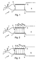
- a burner 1 according to the invention has a fuel injection device 2, which injects a fuel into an oxidant containing gas flow 3 injected. That symbolized here by an arrow Gas flow 3 can be formed, for example, by an air flow his. Methane can also be injected as fuel.
- the fuel injector 2 can be designed here as a so-called "venturi injector".
- the burner 1 Downstream of the fuel injection device 2, the burner 1 contains a catalyst structure 4, which is symbolized here by a rectangular frame.
- This Catalyst structure 4 is from the fuel / gas mixture or reaction mixture through which a catalyst is arranged inside the catalyst structure 4 is that initiates a combustion reaction of the reaction mixture.
- a stabilization zone 5 is arranged in the burner 1, which symbolizes here by a sudden increase in cross-section of the burner 1 is. This stabilization zone 5 merges into a burnout zone 6, in which the actual combustion reaction of the reaction mixture, namely the homogeneous gas phase reaction takes place.
- burner 1 is a component a gas turbine plant, not shown, can in the burnout zone 6 hot combustion gases formed by the homogeneous gas phase reaction a downstream turbine can be supplied. Since the burner 1 initiates and / or stabilizes the combustion reaction by means of the catalyst structure 4, burner 1 works catalytically.
- the catalyst structure 4 has an inlet end 7 and an outlet end 8 and, according to FIGS. 2 and 3, can be subdivided or divided into several zones 9 which follow one another in the flow direction.
- An inlet zone 9 I comprises the inlet end 7, while an outlet zone 9 III contains the outlet end 8.
- a central zone 9 II is formed between inlet end 7 and outlet end 8, which in turn can be divided into several partial zones 9 IIa to 9 IIc or 9 IId .
- the type and number of subdivisions is given here purely by way of example and without restricting the generality.
- Fig. 4 shows a section of the catalyst structure 4, the direction of view runs parallel to a flow direction with which the reaction mixture in the Catalyst structure 4 occurs.
- 4 there is a carrier material 10, from which the catalyst structure 4 is made up of several layers one Material web 11. In the detail shown in FIG. 4, three such layers are made Material webs 11 shown.
- the material webs 11 are each zigzag-shaped here folded, with apex lines 12 of the individual folds in such material webs 11, which is transverse to the direction of flow, corresponding to Fig. 4 in vertical Direction, are adjacent, are oriented differently.
- 4 are the Vertex lines 12 of the upper and lower material webs 11 are oriented such that they move away from a vertical axis towards the right.
- the difference the apex lines 12 of the middle material web 11 are oriented so that they move away from a vertical axis towards the left.
- the adjacent material webs 11 in the vertical axis lie on the intersecting apex lines 12 to each other.
- Between adjacent to each other Layers 11 are formed more or less tortuous channels 13, which allow the flow through the catalyst structure 4.
- the material webs 11 form the walls of these channels 13.
- connection openings 14 are provided in these walls, through which adjacent channels 13 communicate with each other.
- connection openings 14 can thus be mixed in the individual Channels 13 guided flows take place.
- Different degrees of conversion or reaction states that form in the different channels 13 can be by the flow exchange between the channels 13 in essentially balanced.
- FIG. 5 shows a larger section of the catalyst structure 4, whose carrier material 10 also consists of several layers of the material webs11 is constructed. 5, however, is only a section with four material webs 11 played.
- Fig. 5 is a flow direction 15, in Fig. 4 with the viewing direction coincides, represented by an arrow. Cut the apex lines 12 in the special embodiment shown here, the flow direction 15 with an angle of about 45 °. The adjacent crest lines 12 Adjacent material webs 11 are then approximately perpendicular to one another.
- zigzag folded material webs 11 can for the layers also triangular or rectangular folded or corrugated material webs be used.
- FIG. 6 also shows a section of the catalyst structure 4 in which the support material 10 in contrast to the embodiments of FIGS. 4 and 5 not from several material webs, but from a multi-fold material web 16 exists.
- the apex lines 12 of the folds of this material web 16 can doing e.g. run in the longitudinal direction of the catalyst structure 4, in particular parallel to the flow direction 15. Between successive apex lines 12 the material web 16 has flat areas which form flat wall sections 17, that run parallel to each other. Between adjacent wall sections 17 the channels 13 are formed. In these flat wall sections 17 are the Connection openings 14 are formed through which the adjacent channels 13 communicate with each other.
- material for the material web 16 according to FIG. 6 or for the material web 11 4 and 5 for example, one built on metallic fibers Serve fiber tissue, which in the catalytically active sections with a corresponding catalyst is coated. It is also possible to use the material webs 11 and 16 to be formed from a relatively thin metal foil. These materials are characterized by a high thermal conductivity and a low one Heat storage capacity because the combination of these properties into one uniform temperature distribution within the catalyst structure 4 leads and thus temperature peaks and overheating and especially initiation prevent a homogeneous gas phase reaction within the catalyst structure 4.
- the folded material webs 11, from which the individual Layers of the carrier material 10 are formed with flow guide means e.g. be provided in the form of triangular wings 18.
- Each wing 18 is one assigned to the connection openings 14. The flow in a corresponding manner Wing 18 support a redirection of the flow from the one channel through the connection opening 14 into the adjacent channel.
- the vanes 18 also serve as turbulators operating in a flow comes into contact with the wings 18, vortex formation and thus turbulence stimulate.
- connection openings 14, Flow guide and the turbulators in the form of the wing 18 particularly simple e.g. be produced by punching processes.
- 18 two triangle sides cut free so that the wing 18 around the third triangle side can be bent over such that the wing 18 projects into one of the channels.
- By bending the wings 18 out of the material web 11 arise there triangular openings, which form the connecting openings 14.
- the layers are through according to FIG. 8 Rectangularly folded material webs 11 formed, which instead of apex lines Have apex surfaces 19.
- connection openings 14 and Wing 18 which serve as flow guide and turbulators, preferably produced by a punching process with cutting free and bending the wing 18.
- that side of the triangle runs of the wing 18 on which the bending deformation of the wing 18 takes place for example transversely to the direction of extent of the apex surfaces 19 of the associated material web 11.
- a tip 20 of each wing 18 points upstream, that is, opposite the direction of flow.
- the wings 18 can be as far from the respective Stick out wall that they are on a parallel, opposite wall come to the plant.
- FIG. 9 shows an arrangement of seven guide vane structures 21, which are arranged transversely to a flow direction in one of the channels can.
- a guide vane structure 21 forces one flowing through it Flow a rotation around a parallel to the flow direction Axis on.
- the guide vane structures 21 have a hexagonal circumference, which creates a corresponding for the adjacent channels Honeycomb structure results.
- Each of these vane structures 21 has a plurality of blades 22, which are inclined to the direction of flow, and thus are oriented so that the desired rotation occurs downstream of the guide vane structure 21 in the flow.
- the catalyst structure 4 for example, consist entirely of a fiber fabric, which with a Catalyst is coated.
- This structure ensures a low thermal Storage capacity for the catalyst structure 4 and leads to an advantageous Ignition characteristics.
- this structure ensures a favorable Temperature transport and flow exchange between the neighboring ones Channels within the catalyst structure. Due to the surface quality of the fabric material, the walls of the channels have a certain roughness, which causes vortex formation in the flow and thus intensive mixing is promoted.
- the so formed Catalytic converter structure 4 can sufficiently swirl at outlet end 8 or turbulence can be achieved in the flow, so that the burnout zone 6 relative can be built small.
- the inlet zone 9 I is catalytically inactive or inert and is equipped with turbulators, not shown here.
- the inlet zone 9 I works as a static mixer which ensures homogeneous mixing of the gas flow 3 with the injected fuel.
- the support material is coated with a catalyst.
- the individual sub-zones 9 IIa to 9 IId can differ from one another in terms of catalytic activity and / or in terms of flow properties (for example turbulator density).
- the catalyst initiates the combustion reaction of the reaction mixture.
- this catalytically active region of the catalyst structure 4 is specifically designed in such a way that a low ignition temperature is reached, and in addition the formation of a homogeneous gas phase reaction within the catalyst structure 4 is avoided.
- one or the other of the partial zones 9 IIa to 9 IId can also be made catalytically inactive or inert.
- the outlet zone 9 III is again catalytically inactive or inert and has turbulators in order in this way to achieve intensive mixing of the individual channel flows at the outlet 8 of the catalyst structure 4. This intensive swirling also has the consequence here that the burner 1 manages with a relatively short burnout zone 6.
- the inlet zone 9 I is designed in such a way that a relatively strong mixing is formed between the adjacent channels, which causes a correspondingly intensive temperature compensation. This can be achieved in particular by means of appropriately arranged turbulators. Furthermore, the inlet zone 9 I is designed to be catalytically highly active, so that the inlet zone 9 I serves as an ignition zone. These properties of the inlet zone 9 I can be realized particularly simply by using a metal fiber fabric as the carrier material, which is coated with the highly active catalyst. The middle zone 9 II is also coated with a catalyst, the middle zone 9 II being designed for a minimal pressure drop, which reduces the risk that a homogeneous gas phase reaction is ignited within the catalyst structure 4.
- the middle zone 9 II can be subdivided into several partial zones 9 IIa to 9 IIc , which differ from one another, for example, in terms of their catalytic activity.
- active and inert sub-zones can follow one another.
- the outlet zone 9 III again has turbulators for generating an intensive swirling and mixing at the outlet end 8 of the catalyst structure 4.
- the outlet zone 9 III can be designed to be catalytically active or inactive.
- the middle zone 9 II and the outlet zone 9 III can also be made from a porous fiber fabric in this embodiment; alternatively, a thin metal foil or a ceramic carrier material can also be used.
Landscapes
- Engineering & Computer Science (AREA)
- Chemical & Material Sciences (AREA)
- Chemical Kinetics & Catalysis (AREA)
- Combustion & Propulsion (AREA)
- Mechanical Engineering (AREA)
- General Engineering & Computer Science (AREA)
- Gas Burners (AREA)
- Catalysts (AREA)
Abstract
Description
- Fig. 1
- eine stark vereinfachte Prinzipdarstellung eines erfindungsgemäßen Brenners bei einer ersten Ausführungsform,
- Fig. 2
- eine Ansicht wie in Fig. 1, jedoch bei einer zweiten Ausführungsform,
- Fig. 3
- eine Ansicht wie in Fig. 1, jedoch bei einer dritten Ausführungsform,
- Fig. 4
- eine Ansicht auf einen Ausschnitt einer Katalysator-Struktur nach der Erfindung bei einer ersten Ausführungsform,
- Fig. 5
- eine perspektivische Ansicht auf einen Ausschnitt der Katalysator-Struktur, jedoch bei einer zweiten Ausführungsform,
- Fig. 6
- eine Ansicht wie in Fig. 4, jedoch bei einer dritten Ausführungsform,
- Fig. 7
- eine perspektivische Ansicht auf einen Bestandteil der Katalysator-Struktur,
- Fig. 8
- eine Ansicht wie in Fig. 7, jedoch bei einer anderen Ausführungsform, und
- Fig. 9
- eine Ansicht wie in Fig. 7, jedoch bei einer weiteren Ausführungsform.
- 1
- Brenner
- 2
- Kraftstoffeinspritzeinrichtung
- 3
- Gasströmung
- 4
- Katalysator-Struktur
- 5
- Stabilisierungszone
- 6
- Ausbrennzone
- 7
- Einlassende von 4
- 8
- Auslassende von 4
- 9
- Zone von 4
- 9I
- Einlasszone
- 9II
- mittlere Zone
- 9III
- Auslasszone
- 10
- Trägermaterial
- 11
- Materialbahn
- 12
- Scheitellinie
- 13
- Kanal
- 14
- Verbindungsöffnung
- 15
- Anströmrichtung
- 16
- Materialbahn
- 17
- ebener Wandabschnitt
- 18
- Flügel
- 19
- Scheitelfläche
- 20
- Dreieckspitze
- 21
- Leitschaufelstruktur
- 22
- Schaufel
Claims (24)
- Katalytisch arbeitender Brenner, insbesondere für eine Gasturbinenanlage, mit einer Katalysator-Struktur (4), die ein hitzebeständiges Trägermaterial (10) aufweist, das die Wände von mehreren benachbarten Kanälen (13) bildet, welche die Katalysator-Struktur (4) in Längsrichtung durchdringen und eine Durchströmung der Katalysator-Struktur (4) mit einem gasförmigen Reaktionsgemisch ermöglichen, wobei zumindest ein Teil der Wände mit einem Katalysator beschichtet ist, dadurch gekennzeichnet, dass zwischen einem Einlassende (7) und einem Auslassende (8) der Katalysator-Struktur (4) Verbindungsöffnungen (14) in den Wänden ausgebildet sind, durch die benachbarte Kanäle (13) miteinander kommunizieren.
- Brenner nach Anspruch 1, dadurch gekennzeichnet, dass wenigstens einer der Verbindungsöffnungen (14) Strömungsleitmittel (18) zugeordnet sind, die zumindest einen Teil der Strömung eines Kanals (13) in einen durch die Verbindungsöffnung (14) damit kommunizierenden benachbarten Kanal (13) umleiten.
- Brenner nach Anspruch 1 oder 2, dadurch gekennzeichnet, dass wenigstens einer der Verbindungsöffnungen (14) ein Turbulator (18) zugeordnet ist.
- Brenner zumindest nach Anspruch 2, dadurch gekennzeichnet, dass die Strömungsleitmittel als Turbulator (18) ausgebildet sind.
- Brenner nach einem der Ansprüche 1 bis 4, dadurch gekennzeichnet, dass die Kanäle (13) zumindest teilweise einen gewundenen Strömungsweg durch die Katalysator-Struktur (4) bilden.
- Brenner nach einem der Ansprüche 1 bis 5, dadurch gekennzeichnet, dass die Beschichtung der Wände mit dem Katalysator so ausgeführt ist, dass einige der Kanäle (13) katalytisch aktiv sind, während andere Kanäle (13) katalytisch inaktiv oder inert sind.
- Brenner nach einem der Ansprüche 1 bis 6, dadurch gekennzeichnet, dass die Beschichtung der Wände mit dem Katalysator so ausgebildet ist, dass zumindest einige der Kanäle (13) in Strömungsrichtung mindestens eine katalytisch aktive Zone und mindestens eine katalytisch inaktive oder inerte Zone aufweisen.
- Brenner nach einem der Ansprüche 1 bis 7, dadurch gekennzeichnet, dass die Beschichtung der Wände mit dem Katalysator so ausgeführt ist, dass zumindest einige der Kanäle (13) in Strömungsrichtung mehrere aktive Zonen aufweisen, deren katalytische Aktivitäten unterschiedlich ausgebildet sind.
- Brenner nach einem der Ansprüche 1 bis 8, dadurch gekennzeichnet, dass zumindest ein Teil des mit dem Katalysator beschichteten Trägermaterials (10) aus einem porösen Werkstoff besteht.
- Brenner nach einem der Ansprüche 1 bis 9, dadurch gekennzeichnet, dass zumindest ein Teil des mit dem Katalysator beschichteten Trägermaterials (10) aus einem Fasergewebe besteht.
- Brenner nach einem der Ansprüche 1 bis 10, dadurch gekennzeichnet, dass zumindest ein Teil des mit dem Katalysator beschichteten Trägermaterials (10) aus einer Metallfolie besteht.
- Brenner nach einem der Ansprüche 1 bis 11, dadurch gekennzeichnet, dass in den Kanälen (13) Turbulatoren (18) angeordnet sind, wobei diese Turbulatoren entlang der Katalysator-Struktur (4) so in den Kanälen (13) verteilt sind, dass die Katalysator-Struktur (4) in Strömungsrichtung zumindest eine mit den Turbulatoren ausgestattete Zone sowie mindestens eine turbulatorfreie Zone aufweist.
- Brenner nach Anspruch 12, dadurch gekennzeichnet, dass eine der zumindest einen mit den Turbulatoren (18) ausgestatteten Zonen das Auslassende (8) der Katalysator-Struktur (4) aufweist.
- Brenner nach Anspruch 13, dadurch gekennzeichnet, dass die das Auslassende (8) aufweisende Zone (9III) der Katalysator-Struktur (4) katalytisch inaktiv oder inert ausgebildet ist.
- Brenner nach einem der Ansprüche 12 bis 14, dadurch gekennzeichnet, dass eine der zumindest einen mit den Turbulatoren (18) ausgestatteten Zonen das Einlassende (7) der Katalysator-Struktur (4) aufweist, wobei diese Zone (9I) außerdem katalytisch inaktiv oder inert ausgebildet ist.
- Brenner nach einem der Ansprüche 12 bis 15, dadurch gekennzeichnet, dass eine das Einlassende (7) aufweisende Zone (9I) der Katalysator-Struktur (4) mit Turbulatoren (18) ausgestattet und katalytisch inaktiv oder inert ausgebildet ist, dass in einem Bereich zwischen Einlassende (7) und Auslassende (8) der Katalysator-Struktur (4) mindestens eine katalytisch aktive Zone (9II) ausgebildet ist, dass eine das Auslassende (8) aufweisende Zone (9III) der Katalysator-Struktur (4) mit Turbulatoren (18) ausgestattet und katalytisch inaktiv oder inert ausgebildet ist.
- Brenner nach einem der Ansprüche 12 bis 15, dadurch gekennzeichnet, dass eine das Einlassende (7) aufweisende Zone (9I) der Katalysator-Struktur (4) mit Turbulatoren (18) ausgestattet und katalytisch hoch aktiv ausgebildet ist, dass in einem Bereich zwischen Einlassende (7) und Auslassende (8) der Katalysator-Struktur (4) eine turbulatorfreie Zone (9II) katalytisch aktiv ausgebildet ist, dass eine das Auslassende (8) aufweisende Zone (9III) der Katalysator-Struktur (4) mit Turbulatoren (18) ausgestattet ist.
- Brenner nach einem der Ansprüche 1 bis 17, dadurch gekennzeichnet, dass das Trägermaterial (10) zumindest teilweise aus mehreren Lagen besteht, wobei jede Lage aus einer zick-zack-förmig oder dreieckförmig oder rechteckwellig gefalteten und/oder gewellten Materialbahn (11) gebildet ist, wobei die Scheitellinien (12) oder Scheitelflächen (19) der Falten und/oder Wellen bei quer zur Strömungsrichtung benachbarten Materialbahnen (11) unterschiedlich ausgerichtet sind, wobei benachbarte Materialbahnen (11) an den sich schneidenden Scheitellinien (12) oder Scheitelflächen (19) aneinander anliegen und zwischen sich die Kanäle (13) ausbilden.
- Brenner nach Anspruch 18, dadurch gekennzeichnet, dass die Scheitellinien (12) oder Scheitelflächen (19) geneigt zur Längsrichtung der Katalysator-Struktur (4) ausgerichtet sind.
- Brenner nach einem der Ansprüche 1 bis 19, dadurch gekennzeichnet, dass das Trägermaterial (10) zumindest teilweise aus einer mehrfach gefalteten Materialbahn (16) besteht, wobei die Scheitellinien (12) oder Scheitelflächen der Falten etwa in Längsrichtung der Katalysator-Struktur (4) verlaufen, wobei zwischen aufeinanderfolgenden Scheitellinien (12) oder Scheitelflächen ebene Wandabschnitte (17) ausgebildet sind, wobei benachbarte ebene Wandabschnitte (17) parallel zueinander verlaufen und wobei zwischen den benachbarten Wandabschnitten (17) die Kanäle (13) ausgebildet sind.
- Brenner nach einem der Ansprüche 1 bis 20, dadurch gekennzeichnet, dass die Strömungsleitmittel und/oder die Turbulatoren in den Wänden durch dreieckige Flügel (18) gebildet sind, wobei zwei Dreiecksseiten des Flügels (18) freigeschnitten sind und wobei der Flügel (18) an der dritten Dreiecksseite umgebogen ist, so dass der Flügel (18) in einen der Kanäle (13) hineinragt, wobei die dabei in den Wänden entstehenden Dreiecksöffnungen die Verbindungsöffnungen (14) bilden.
- Brenner nach Anspruch 21, dadurch gekennzeichnet, dass die umgebogene Dreiecksseite des Flügels (18) etwa quer zur Erstreckungsrichtung der Scheitellinien (12) oder Scheitelflächen (19) der Materialbahn (11) verläuft und dass die Dreiecksspitze (20) des Flügels (18) stromauf zeigt.
- Brenner nach einem der Ansprüche 1 bis 22 dadurch gekennzeichnet, dass wenigstens einer der Kanäle (13) entlang der Katalysator-Struktur (4) an mindestens einer Stelle eine quer zur Strömungsrichtung ausgerichtete Leitschaufelstruktur (21) aufweist, die einer durch sie hindurchströmenden Strömung eine Rotation um eine parallel zur Strömungsrichtung verlaufende Achse aufzwingt.
- Verwendung einer Katalysator-Struktur mit einem hitzebeständigen Trägermaterial (10), das die Wände mehrerer benachbarter Kanäle (13) bildet, welche die Katalysator-Struktur (4) in Längsrichtung durchdringen und eine Durchströmung der Katalysator-Struktur (4) mit einem gasförmigen Reaktionsgemisch ermöglichen, wobei zumindest ein Teil der Wände mit einem Katalysator beschichtet ist und wobei zwischen einem Einlassende (7) und einem Auslassende (8) der Katalysator-Struktur (4) Verbindungsöffnungen (14) in den Wänden ausgebildet sind, durch die benachbarte Kanäle (13) miteinander kommunizieren, in einem katalytisch arbeitenden Brenner (1).
Applications Claiming Priority (2)
| Application Number | Priority Date | Filing Date | Title |
|---|---|---|---|
| DE10119035A DE10119035A1 (de) | 2001-04-18 | 2001-04-18 | Katalytisch arbeitender Brenner |
| DE10119035 | 2001-04-18 |
Publications (2)
| Publication Number | Publication Date |
|---|---|
| EP1251314A2 true EP1251314A2 (de) | 2002-10-23 |
| EP1251314A3 EP1251314A3 (de) | 2003-10-01 |
Family
ID=7681873
Family Applications (1)
| Application Number | Title | Priority Date | Filing Date |
|---|---|---|---|
| EP02405294A Withdrawn EP1251314A3 (de) | 2001-04-18 | 2002-04-12 | Katalytisch arbeitender Brenner |
Country Status (6)
| Country | Link |
|---|---|
| US (1) | US6887067B2 (de) |
| EP (1) | EP1251314A3 (de) |
| JP (1) | JP2003028426A (de) |
| CA (1) | CA2381677A1 (de) |
| DE (1) | DE10119035A1 (de) |
| NO (1) | NO20021769L (de) |
Cited By (1)
| Publication number | Priority date | Publication date | Assignee | Title |
|---|---|---|---|---|
| EP1491824B1 (de) * | 2003-06-27 | 2017-01-25 | General Electric Technology GmbH | Katalytischer Reaktor und zugehöriges Betriebsverfahren |
Families Citing this family (30)
| Publication number | Priority date | Publication date | Assignee | Title |
|---|---|---|---|---|
| EP1255078A1 (de) * | 2001-04-30 | 2002-11-06 | ALSTOM (Switzerland) Ltd | Katalysator |
| EP1255079A1 (de) * | 2001-04-30 | 2002-11-06 | ALSTOM (Switzerland) Ltd | Katalysator |
| EP1532395B1 (de) * | 2002-08-30 | 2016-11-16 | General Electric Technology GmbH | Verfahren und vorrichtung zum vermischen von fluidströmungen |
| US6829896B2 (en) * | 2002-12-13 | 2004-12-14 | Siemens Westinghouse Power Corporation | Catalytic oxidation module for a gas turbine engine |
| DE10339468B4 (de) * | 2003-08-27 | 2008-11-13 | Oberland Mangold Gmbh | Katalysatorkörper und Abgasanlage für einen Kleinmotor sowie Verfahren zur Herstellung des Katalysatorkörpers |
| WO2005047769A2 (en) * | 2003-11-14 | 2005-05-26 | Oglesby & Butler Research & Development Limited | A converting device for converting fuel gas to heat and a gas powered heating device |
| US20070237692A1 (en) * | 2006-04-10 | 2007-10-11 | United Technologies Corporation | Catalytic reactor with tube inserts |
| JP2011503411A (ja) * | 2007-11-12 | 2011-01-27 | インパルス エンジン テクノロジー ピーティーワイ リミテッド | マフラー |
| US8468803B2 (en) * | 2011-02-26 | 2013-06-25 | International Engine Intellectual Property Company, Llc | Soot resistant diesel fuel reformer for diesel engine emissions aftertreatment |
| CN102798123B (zh) * | 2011-05-26 | 2016-05-04 | 中山炫能燃气科技股份有限公司 | 一种红外线金属发热体及其制作方法 |
| US10571124B2 (en) | 2013-02-14 | 2020-02-25 | Clearsign Combustion Corporation | Selectable dilution low NOx burner |
| WO2015112950A1 (en) | 2014-01-24 | 2015-07-30 | Clearsign Combustion Corporation | LOW NOx FIRE TUBE BOILER |
| US10458649B2 (en) | 2013-02-14 | 2019-10-29 | Clearsign Combustion Corporation | Horizontally fired burner with a perforated flame holder |
| US10125983B2 (en) | 2013-02-14 | 2018-11-13 | Clearsign Combustion Corporation | High output porous tile burner |
| WO2014127306A1 (en) | 2013-02-14 | 2014-08-21 | Clearsign Combustion Corporation | SELECTABLE DILUTION LOW NOx BURNER |
| US11460188B2 (en) | 2013-02-14 | 2022-10-04 | Clearsign Technologies Corporation | Ultra low emissions firetube boiler burner |
| US10386062B2 (en) | 2013-02-14 | 2019-08-20 | Clearsign Combustion Corporation | Method for operating a combustion system including a perforated flame holder |
| US10119704B2 (en) | 2013-02-14 | 2018-11-06 | Clearsign Combustion Corporation | Burner system including a non-planar perforated flame holder |
| CA2892229A1 (en) * | 2013-02-14 | 2014-08-21 | Clearsign Combustion Corporation | Startup method and mechanism for a burner having a perforated flame holder |
| US10190767B2 (en) | 2013-03-27 | 2019-01-29 | Clearsign Combustion Corporation | Electrically controlled combustion fluid flow |
| WO2015042613A1 (en) * | 2013-09-23 | 2015-03-26 | Christopher A. Wiklof | POROUS FLAME HOLDER FOR LOW NOx COMBUSTION |
| EP3049721A4 (de) | 2013-09-23 | 2017-09-20 | Clearsign Combustion Corporation | Brennersystem mit mehreren perforierten flammenhaltern und verfahren zum betrieb |
| EP3055616B1 (de) * | 2013-10-07 | 2020-12-09 | ClearSign Technologies Corporation | Brenner für vorgemischten brennstoff mit perforiertem flammenhalter |
| CN105637293B (zh) * | 2013-10-07 | 2018-04-27 | 克利尔赛恩燃烧公司 | 具有有孔火焰保持器的水平点火式燃烧器 |
| CN106103338B (zh) | 2014-02-14 | 2018-04-20 | 克利尔赛恩燃烧公司 | 具有有孔火焰保持器的顶烧式燃烧器 |
| WO2016134061A1 (en) | 2015-02-17 | 2016-08-25 | Clearsign Combustion Corporation | Perforated flame holder with adjustable fuel nozzle |
| US10514165B2 (en) | 2016-07-29 | 2019-12-24 | Clearsign Combustion Corporation | Perforated flame holder and system including protection from abrasive or corrosive fuel |
| US10539326B2 (en) | 2016-09-07 | 2020-01-21 | Clearsign Combustion Corporation | Duplex burner with velocity-compensated mesh and thickness |
| WO2022115349A1 (en) * | 2020-11-30 | 2022-06-02 | Corning Incorporated | Electrically powered catalyst heater for fluid treatment systems |
| CN121611901A (zh) * | 2025-12-25 | 2026-03-06 | 辽宁材料实验室 | 一种多孔燃烧介质及多孔介质燃烧器 |
Citations (6)
| Publication number | Priority date | Publication date | Assignee | Title |
|---|---|---|---|---|
| US5248251A (en) | 1990-11-26 | 1993-09-28 | Catalytica, Inc. | Graded palladium-containing partial combustion catalyst and a process for using it |
| US5512250A (en) | 1994-03-02 | 1996-04-30 | Catalytica, Inc. | Catalyst structure employing integral heat exchange |
| US5850731A (en) | 1995-12-22 | 1998-12-22 | General Electric Co. | Catalytic combustor with lean direct injection of gas fuel for low emissions combustion and methods of operation |
| WO1999034911A1 (en) | 1998-01-02 | 1999-07-15 | Abb Lummus Global Inc. | Structured packing and element therefor |
| WO1999062629A1 (en) | 1998-05-29 | 1999-12-09 | Abb Lummus Global Inc. | Structured packing and element therefor |
| US6015285A (en) | 1998-01-30 | 2000-01-18 | Gas Research Institute | Catalytic combustion process |
Family Cites Families (61)
| Publication number | Priority date | Publication date | Assignee | Title |
|---|---|---|---|---|
| US2490079A (en) * | 1944-04-18 | 1949-12-06 | Francis L Melvill | Contacting apparatus |
| US2526657A (en) * | 1945-07-13 | 1950-10-24 | Phillips Petroleum Co | Method of contacting vapors with a solid catalytic material |
| US3492098A (en) * | 1965-12-01 | 1970-01-27 | Universal Oil Prod Co | Multiple section catalyst unit |
| US3819334A (en) * | 1970-10-27 | 1974-06-25 | Mitsui Mining & Smelting Co | Catalytic reaction apparatus for purifying waste gases containing carbon monoxide |
| US3773894A (en) * | 1971-07-22 | 1973-11-20 | Exxon | Nitrogen oxide conversion using reinforced nickel-copper catalysts |
| US3785781A (en) * | 1971-10-04 | 1974-01-15 | Universal Oil Prod Co | Apparatus for catalytically converting fluid |
| US4032310A (en) * | 1974-05-15 | 1977-06-28 | Ignoffo Vincent E | Muffler and exhaust gas purifier for internal combustion engines |
| US3928691A (en) * | 1974-06-17 | 1975-12-23 | Richard A Knudson | Reinforced panels and method of constructing same |
| US4072007A (en) * | 1976-03-03 | 1978-02-07 | Westinghouse Electric Corporation | Gas turbine combustor employing plural catalytic stages |
| US4154568A (en) * | 1977-05-24 | 1979-05-15 | Acurex Corporation | Catalytic combustion process and apparatus |
| CA1104111A (en) * | 1977-06-20 | 1981-06-30 | United Kingdom Atomic Energy Authority | Catalyst supports |
| US4285838A (en) * | 1977-12-08 | 1981-08-25 | Babcock-Hitachi Kabushiki Kaisha | Method of producing plate-shaped catalyst unit for NOx reduction of exhaust gas |
| JPS57150443A (en) * | 1981-03-12 | 1982-09-17 | Matsushita Electric Ind Co Ltd | Combustion catalyst body |
| US4530418A (en) * | 1982-06-01 | 1985-07-23 | Currie Neil L | Automotive exhaust system |
| DE3341868A1 (de) * | 1983-11-19 | 1985-05-30 | Süddeutsche Kühlerfabrik Julius Fr. Behr GmbH & Co KG, 7000 Stuttgart | Matrix fuer einen katalytischen reaktor |
| JPS60179101A (ja) * | 1984-02-28 | 1985-09-13 | Ngk Insulators Ltd | 流体接触用多孔体 |
| US4672809A (en) * | 1984-09-07 | 1987-06-16 | Cornelison Richard C | Catalytic converter for a diesel engine |
| DE3574937D1 (de) * | 1985-05-14 | 1990-02-01 | Sulzer Ag | Reaktor zum durchfuehren von heterogenen, katalysierten chemischen reaktionen. |
| DE3530893A1 (de) * | 1985-08-29 | 1987-03-05 | Interatom | Wachstumskompensierender metallischer abgaskatalysatortraegerkoerper und blech zu seiner herstellung |
| US4676934A (en) * | 1985-09-27 | 1987-06-30 | Jaeger Products, Inc. | Structured WV packing elements |
| SE454101B (sv) * | 1986-03-10 | 1988-03-28 | Sven Runo Vilhelm Gebelius | Avgassystem vid forbrenningsmotor |
| US4870824A (en) * | 1987-08-24 | 1989-10-03 | Westinghouse Electric Corp. | Passively cooled catalytic combustor for a stationary combustion turbine |
| DE3742891A1 (de) * | 1987-12-17 | 1989-06-29 | Bayerische Motoren Werke Ag | Gasturbinenanlage |
| US4882130A (en) * | 1988-06-07 | 1989-11-21 | Ngk Insulators, Ltd. | Porous structure of fluid contact |
| US5026273A (en) * | 1988-07-15 | 1991-06-25 | W. R. Grace & Co.-Conn. | High temperature combuster |
| US5346389A (en) | 1989-02-24 | 1994-09-13 | W. R. Grace & Co.-Conn. | Combustion apparatus for high-temperature environment |
| US5202303A (en) * | 1989-02-24 | 1993-04-13 | W. R. Grace & Co.-Conn. | Combustion apparatus for high-temperature environment |
| US4928485A (en) * | 1989-06-06 | 1990-05-29 | W. R. Grace & Co.,-Conn. | Metallic core member for catalytic converter and catalytic converter containing same |
| US5403559A (en) * | 1989-07-18 | 1995-04-04 | Emitec Gesellschaft Fuer Emissionstechnologie | Device for cleaning exhaust gases of motor vehicles |
| DE8909128U1 (de) * | 1989-07-27 | 1990-11-29 | Emitec Gesellschaft für Emissionstechnologie mbH, 5204 Lohmar | Wabenkörper mit internen Anströmkanten, insbesondere Katalysatorkörper für Kraftfahrzeuge |
| JPH03181338A (ja) * | 1989-12-11 | 1991-08-07 | Gebr Sulzer Ag | 触媒エレメントおよび触媒反応用反応器 |
| GB9027331D0 (en) * | 1990-12-18 | 1991-02-06 | Ici Plc | Catalytic combustion |
| US5312694A (en) * | 1991-10-17 | 1994-05-17 | Ishino Corporation Co., Ltd. | Material for catalyzer for purification of exhaust gas and catalyzer using such a material |
| US5328359A (en) * | 1992-05-19 | 1994-07-12 | W. R. Grace & Co.-Conn. | Ignition stage for a high temperature combustor |
| DE4221763A1 (de) * | 1992-07-02 | 1994-01-05 | Schwaebische Huettenwerke Gmbh | Verfahren zum Herstellen eines Katalysators |
| FR2695326B1 (fr) * | 1992-09-08 | 1994-12-02 | Strasbourg Ecole Nale Sup Arts | Matrice métallique de réacteur catalytique pour le traitement des gaz de combustion. |
| JPH06254413A (ja) * | 1993-03-01 | 1994-09-13 | Ngk Insulators Ltd | 乱流穴を有するハニカム体 |
| WO1994020790A1 (en) * | 1993-03-01 | 1994-09-15 | Engelhard Corporation | Improved catalytic combustion system including a separator body |
| AU6268094A (en) * | 1993-03-04 | 1994-09-26 | Engelhard Corporation | Improved substrate configuration for catalytic combustion system |
| US5820832A (en) * | 1993-05-13 | 1998-10-13 | Siemens Aktiengesellschaft | Plate-type catalytic converter |
| US5460002A (en) * | 1993-05-21 | 1995-10-24 | General Electric Company | Catalytically-and aerodynamically-assisted liner for gas turbine combustors |
| AU681271B2 (en) * | 1994-06-07 | 1997-08-21 | Westinghouse Electric Corporation | Method and apparatus for sequentially staged combustion using a catalyst |
| JPH07328452A (ja) * | 1994-06-13 | 1995-12-19 | Showa Aircraft Ind Co Ltd | 触媒装置用金属担体 |
| JPH08177473A (ja) * | 1994-12-22 | 1996-07-09 | Nippon Soken Inc | 排ガス浄化装置 |
| US5540899A (en) * | 1994-12-22 | 1996-07-30 | Uop | BI-directional control of temperatures in reactant channels |
| FR2732752B1 (fr) * | 1995-04-05 | 1997-05-16 | Applic Gaz Sa | Bruleur catalytique a air induit, et appareil integrant un tel bruleur |
| US6116014A (en) * | 1995-06-05 | 2000-09-12 | Catalytica, Inc. | Support structure for a catalyst in a combustion reaction chamber |
| US5628181A (en) * | 1995-06-07 | 1997-05-13 | Precision Combustion, Inc. | Flashback system |
| DE19527583C2 (de) * | 1995-07-28 | 1998-01-29 | Max Rhodius Gmbh | Brenner, insbesondere für Heizungsanlagen |
| DE19544683A1 (de) * | 1995-11-30 | 1997-06-05 | Buderus Heiztechnik Gmbh | Katalytischer Brenner |
| DE29611143U1 (de) * | 1996-06-25 | 1996-09-12 | Emitec Gesellschaft für Emissionstechnologie mbH, 53797 Lohmar | Konischer Wabenkörper mit Longitudinalstrukturen |
| US5916128A (en) * | 1997-02-21 | 1999-06-29 | Degussa Corporation | Sound deadening and catalyst treating system |
| ES2214645T3 (es) * | 1997-08-20 | 2004-09-16 | Calsonic Kansei Corporation | Pelicula delgada metalica para soporte de catalizador metalico y convertidor de catalizador metalico que emplea la pelicula delgada metalica. |
| US6174159B1 (en) * | 1999-03-18 | 2001-01-16 | Precision Combustion, Inc. | Method and apparatus for a catalytic firebox reactor |
| US6179608B1 (en) * | 1999-05-28 | 2001-01-30 | Precision Combustion, Inc. | Swirling flashback arrestor |
| US6667017B2 (en) * | 1999-10-15 | 2003-12-23 | Abb Lummus Global, Inc. | Process for removing environmentally harmful compounds |
| WO2001028665A1 (en) * | 1999-10-15 | 2001-04-26 | Abb Lummus Global, Inc. | Conversion of nitrogen oxides in the presence of a catalyst supported of a mesh-like structure |
| EP1179709B1 (de) | 2000-08-09 | 2005-12-14 | Calsonic Kansei Corporation | Mit Wasserstoffverbrennung betriebene Heizungsanlage |
| EP1197256A1 (de) * | 2000-10-13 | 2002-04-17 | ALSTOM (Switzerland) Ltd | Verfahren und Vorrichtung zur Erzeugung von heissen Verbrennungsabgasen |
| DE50212351D1 (de) * | 2001-04-30 | 2008-07-24 | Alstom Technology Ltd | Vorrichtung zum Verbrennen eines gasförmigen Brennstoff-Oxidator-Gemischs |
| EP1255079A1 (de) * | 2001-04-30 | 2002-11-06 | ALSTOM (Switzerland) Ltd | Katalysator |
-
2001
- 2001-04-18 DE DE10119035A patent/DE10119035A1/de not_active Withdrawn
- 2001-04-30 US US09/843,836 patent/US6887067B2/en not_active Expired - Fee Related
-
2002
- 2002-04-12 EP EP02405294A patent/EP1251314A3/de not_active Withdrawn
- 2002-04-15 NO NO20021769A patent/NO20021769L/no not_active Application Discontinuation
- 2002-04-15 CA CA002381677A patent/CA2381677A1/en not_active Abandoned
- 2002-04-17 JP JP2002115017A patent/JP2003028426A/ja not_active Withdrawn
Patent Citations (6)
| Publication number | Priority date | Publication date | Assignee | Title |
|---|---|---|---|---|
| US5248251A (en) | 1990-11-26 | 1993-09-28 | Catalytica, Inc. | Graded palladium-containing partial combustion catalyst and a process for using it |
| US5512250A (en) | 1994-03-02 | 1996-04-30 | Catalytica, Inc. | Catalyst structure employing integral heat exchange |
| US5850731A (en) | 1995-12-22 | 1998-12-22 | General Electric Co. | Catalytic combustor with lean direct injection of gas fuel for low emissions combustion and methods of operation |
| WO1999034911A1 (en) | 1998-01-02 | 1999-07-15 | Abb Lummus Global Inc. | Structured packing and element therefor |
| US6015285A (en) | 1998-01-30 | 2000-01-18 | Gas Research Institute | Catalytic combustion process |
| WO1999062629A1 (en) | 1998-05-29 | 1999-12-09 | Abb Lummus Global Inc. | Structured packing and element therefor |
Cited By (1)
| Publication number | Priority date | Publication date | Assignee | Title |
|---|---|---|---|---|
| EP1491824B1 (de) * | 2003-06-27 | 2017-01-25 | General Electric Technology GmbH | Katalytischer Reaktor und zugehöriges Betriebsverfahren |
Also Published As
| Publication number | Publication date |
|---|---|
| US20020155403A1 (en) | 2002-10-24 |
| NO20021769L (no) | 2002-10-21 |
| JP2003028426A (ja) | 2003-01-29 |
| EP1251314A3 (de) | 2003-10-01 |
| NO20021769D0 (no) | 2002-04-15 |
| DE10119035A1 (de) | 2002-10-24 |
| CA2381677A1 (en) | 2002-10-18 |
| US6887067B2 (en) | 2005-05-03 |
Similar Documents
| Publication | Publication Date | Title |
|---|---|---|
| EP1251314A2 (de) | Katalytisch arbeitender Brenner | |
| DE4426351B4 (de) | Brennkammer für eine Gasturbine | |
| EP1532395B1 (de) | Verfahren und vorrichtung zum vermischen von fluidströmungen | |
| DE10217913B4 (de) | Gasturbine mit Brennkammer zur flammenlosen Oxidation | |
| EP1279898B1 (de) | Vormischbrenner mit hoher Flammenstabilität | |
| DE69526492T2 (de) | Verbesserte katalysatorstruktur mit integriertem wärmeaustausch | |
| DE69729505T2 (de) | Arbeitsweise einer Gasturbinenbrennkammer | |
| DE69719591T2 (de) | Arbeitsweise einer katalytischen Brennkammer | |
| CH680014A5 (de) | ||
| CH674561A5 (de) | ||
| EP0481111B1 (de) | Brennkammer einer Gasturbine | |
| DE112014005025B4 (de) | Ringförmige Verbrennungskammer in einem Gasturbinen-Triebwerk und Verfahren zu dessen Betrieb | |
| DE4411623A1 (de) | Vormischbrenner | |
| CH680084A5 (de) | ||
| EP0851172B1 (de) | Brenner und Verfahren zum Betrieb einer Brennkammer mit einem flüssigen und/oder gasförmigen Brennstoff | |
| EP0724114A2 (de) | Brenner | |
| EP1800062B1 (de) | Brenner zur verbrennung eines niederkalorischen brenngases und verfahren zum betrieb eines brenners | |
| DE2261596B2 (de) | Verfahren und Brennkammer zum Verbrennen eines Brennstoffes | |
| DE102017118165B4 (de) | Brennerkopf, Brennersystem und Verwendung des Brennersystems | |
| EP1255077B1 (de) | Vorrichtung zum Verbrennen eines gasförmigen Brennstoff-Oxidator-Gemischs | |
| DE69526212T2 (de) | Verbesserte verfahren und katalytische, struktur, benutzend integralen wärmeaustausch mit wahlweise vorgeschaltetem flammenhalter | |
| DE19537636B4 (de) | Kraftwerksanlage | |
| EP1255079A1 (de) | Katalysator | |
| EP1255078A1 (de) | Katalysator | |
| EP1491824B1 (de) | Katalytischer Reaktor und zugehöriges Betriebsverfahren |
Legal Events
| Date | Code | Title | Description |
|---|---|---|---|
| PUAI | Public reference made under article 153(3) epc to a published international application that has entered the european phase |
Free format text: ORIGINAL CODE: 0009012 |
|
| AK | Designated contracting states |
Kind code of ref document: A2 Designated state(s): AT BE CH CY DE DK ES FI FR GB GR IE IT LI LU MC NL PT SE TR |
|
| AX | Request for extension of the european patent |
Free format text: AL;LT;LV;MK;RO;SI |
|
| PUAL | Search report despatched |
Free format text: ORIGINAL CODE: 0009013 |
|
| AK | Designated contracting states |
Kind code of ref document: A3 Designated state(s): AT BE CH CY DE DK ES FI FR GB GR IE IT LI LU MC NL PT SE TR |
|
| AX | Request for extension of the european patent |
Extension state: AL LT LV MK RO SI |
|
| RIC1 | Information provided on ipc code assigned before grant |
Ipc: 7F 23C 11/00 B Ipc: 7F 23R 3/40 A |
|
| RAP1 | Party data changed (applicant data changed or rights of an application transferred) |
Owner name: ALSTOM TECHNOLOGY LTD |
|
| 17P | Request for examination filed |
Effective date: 20040320 |
|
| AKX | Designation fees paid |
Designated state(s): DE FR GB SE |
|
| STAA | Information on the status of an ep patent application or granted ep patent |
Free format text: STATUS: THE APPLICATION IS DEEMED TO BE WITHDRAWN |
|
| 18D | Application deemed to be withdrawn |
Effective date: 20071031 |