EP1249919B1 - Rotor de machine electrique tournante - Google Patents
Rotor de machine electrique tournante Download PDFInfo
- Publication number
- EP1249919B1 EP1249919B1 EP02291384A EP02291384A EP1249919B1 EP 1249919 B1 EP1249919 B1 EP 1249919B1 EP 02291384 A EP02291384 A EP 02291384A EP 02291384 A EP02291384 A EP 02291384A EP 1249919 B1 EP1249919 B1 EP 1249919B1
- Authority
- EP
- European Patent Office
- Prior art keywords
- rotor
- fact
- magnets
- stator
- rotor according
- Prior art date
- Legal status (The legal status is an assumption and is not a legal conclusion. Google has not performed a legal analysis and makes no representation as to the accuracy of the status listed.)
- Expired - Lifetime
Links
- 230000000694 effects Effects 0.000 claims description 8
- 239000000696 magnetic material Substances 0.000 claims description 8
- XAGFODPZIPBFFR-UHFFFAOYSA-N aluminium Chemical compound [Al] XAGFODPZIPBFFR-UHFFFAOYSA-N 0.000 claims description 7
- 229910052782 aluminium Inorganic materials 0.000 claims description 7
- 230000007423 decrease Effects 0.000 claims description 6
- 239000000463 material Substances 0.000 claims description 6
- 230000000295 complement effect Effects 0.000 claims description 5
- 230000004907 flux Effects 0.000 abstract description 8
- 238000004519 manufacturing process Methods 0.000 description 17
- 238000004804 winding Methods 0.000 description 11
- 239000004020 conductor Substances 0.000 description 8
- 229910000831 Steel Inorganic materials 0.000 description 5
- 238000001816 cooling Methods 0.000 description 5
- 239000010959 steel Substances 0.000 description 5
- 230000001360 synchronised effect Effects 0.000 description 5
- 230000008901 benefit Effects 0.000 description 4
- 238000002955 isolation Methods 0.000 description 4
- 230000002093 peripheral effect Effects 0.000 description 4
- 239000011347 resin Substances 0.000 description 4
- 229920005989 resin Polymers 0.000 description 4
- 230000005355 Hall effect Effects 0.000 description 3
- 230000003247 decreasing effect Effects 0.000 description 3
- 238000010438 heat treatment Methods 0.000 description 3
- 238000005470 impregnation Methods 0.000 description 3
- 238000012423 maintenance Methods 0.000 description 3
- 239000000243 solution Substances 0.000 description 3
- 229910000838 Al alloy Inorganic materials 0.000 description 2
- 230000006835 compression Effects 0.000 description 2
- 238000007906 compression Methods 0.000 description 2
- 238000001514 detection method Methods 0.000 description 2
- 238000010586 diagram Methods 0.000 description 2
- 230000006870 function Effects 0.000 description 2
- 238000000034 method Methods 0.000 description 2
- 230000008439 repair process Effects 0.000 description 2
- RYGMFSIKBFXOCR-UHFFFAOYSA-N Copper Chemical compound [Cu] RYGMFSIKBFXOCR-UHFFFAOYSA-N 0.000 description 1
- 230000009471 action Effects 0.000 description 1
- 239000000853 adhesive Substances 0.000 description 1
- 230000001070 adhesive effect Effects 0.000 description 1
- 238000004364 calculation method Methods 0.000 description 1
- 238000005119 centrifugation Methods 0.000 description 1
- 230000008859 change Effects 0.000 description 1
- 239000002131 composite material Substances 0.000 description 1
- 238000010276 construction Methods 0.000 description 1
- 229910052802 copper Inorganic materials 0.000 description 1
- 239000010949 copper Substances 0.000 description 1
- 238000005336 cracking Methods 0.000 description 1
- 238000006073 displacement reaction Methods 0.000 description 1
- 230000005284 excitation Effects 0.000 description 1
- 239000004744 fabric Substances 0.000 description 1
- 238000005194 fractionation Methods 0.000 description 1
- 238000002347 injection Methods 0.000 description 1
- 239000007924 injection Substances 0.000 description 1
- 238000009413 insulation Methods 0.000 description 1
- 238000005461 lubrication Methods 0.000 description 1
- 238000003754 machining Methods 0.000 description 1
- 230000005415 magnetization Effects 0.000 description 1
- 230000007257 malfunction Effects 0.000 description 1
- 238000005259 measurement Methods 0.000 description 1
- 238000003032 molecular docking Methods 0.000 description 1
- 244000045947 parasite Species 0.000 description 1
- 238000005192 partition Methods 0.000 description 1
- 230000010363 phase shift Effects 0.000 description 1
- 229920006395 saturated elastomer Polymers 0.000 description 1
- 230000035945 sensitivity Effects 0.000 description 1
- 238000000926 separation method Methods 0.000 description 1
- 238000007493 shaping process Methods 0.000 description 1
- 238000005491 wire drawing Methods 0.000 description 1
Images


Classifications
-
- H—ELECTRICITY
- H02—GENERATION; CONVERSION OR DISTRIBUTION OF ELECTRIC POWER
- H02K—DYNAMO-ELECTRIC MACHINES
- H02K7/00—Arrangements for handling mechanical energy structurally associated with dynamo-electric machines, e.g. structural association with mechanical driving motors or auxiliary dynamo-electric machines
- H02K7/14—Structural association with mechanical loads, e.g. with hand-held machine tools or fans
-
- H—ELECTRICITY
- H02—GENERATION; CONVERSION OR DISTRIBUTION OF ELECTRIC POWER
- H02K—DYNAMO-ELECTRIC MACHINES
- H02K1/00—Details of the magnetic circuit
- H02K1/06—Details of the magnetic circuit characterised by the shape, form or construction
- H02K1/22—Rotating parts of the magnetic circuit
- H02K1/27—Rotor cores with permanent magnets
- H02K1/2786—Outer rotors
- H02K1/2787—Outer rotors the magnetisation axis of the magnets being perpendicular to the rotor axis
- H02K1/2789—Outer rotors the magnetisation axis of the magnets being perpendicular to the rotor axis the rotor consisting of two or more circumferentially positioned magnets
- H02K1/2791—Surface mounted magnets; Inset magnets
-
- B—PERFORMING OPERATIONS; TRANSPORTING
- B66—HOISTING; LIFTING; HAULING
- B66D—CAPSTANS; WINCHES; TACKLES, e.g. PULLEY BLOCKS; HOISTS
- B66D1/00—Rope, cable, or chain winding mechanisms; Capstans
- B66D1/02—Driving gear
- B66D1/12—Driving gear incorporating electric motors
-
- H—ELECTRICITY
- H02—GENERATION; CONVERSION OR DISTRIBUTION OF ELECTRIC POWER
- H02K—DYNAMO-ELECTRIC MACHINES
- H02K1/00—Details of the magnetic circuit
- H02K1/06—Details of the magnetic circuit characterised by the shape, form or construction
- H02K1/12—Stationary parts of the magnetic circuit
- H02K1/14—Stator cores with salient poles
- H02K1/141—Stator cores with salient poles consisting of C-shaped cores
-
- H—ELECTRICITY
- H02—GENERATION; CONVERSION OR DISTRIBUTION OF ELECTRIC POWER
- H02K—DYNAMO-ELECTRIC MACHINES
- H02K1/00—Details of the magnetic circuit
- H02K1/06—Details of the magnetic circuit characterised by the shape, form or construction
- H02K1/12—Stationary parts of the magnetic circuit
- H02K1/14—Stator cores with salient poles
- H02K1/146—Stator cores with salient poles consisting of a generally annular yoke with salient poles
-
- H—ELECTRICITY
- H02—GENERATION; CONVERSION OR DISTRIBUTION OF ELECTRIC POWER
- H02K—DYNAMO-ELECTRIC MACHINES
- H02K1/00—Details of the magnetic circuit
- H02K1/06—Details of the magnetic circuit characterised by the shape, form or construction
- H02K1/12—Stationary parts of the magnetic circuit
- H02K1/18—Means for mounting or fastening magnetic stationary parts on to, or to, the stator structures
- H02K1/185—Means for mounting or fastening magnetic stationary parts on to, or to, the stator structures to outer stators
-
- H—ELECTRICITY
- H02—GENERATION; CONVERSION OR DISTRIBUTION OF ELECTRIC POWER
- H02K—DYNAMO-ELECTRIC MACHINES
- H02K11/00—Structural association of dynamo-electric machines with electric components or with devices for shielding, monitoring or protection
- H02K11/20—Structural association of dynamo-electric machines with electric components or with devices for shielding, monitoring or protection for measuring, monitoring, testing, protecting or switching
- H02K11/25—Devices for sensing temperature, or actuated thereby
-
- H—ELECTRICITY
- H02—GENERATION; CONVERSION OR DISTRIBUTION OF ELECTRIC POWER
- H02K—DYNAMO-ELECTRIC MACHINES
- H02K21/00—Synchronous motors having permanent magnets; Synchronous generators having permanent magnets
- H02K21/12—Synchronous motors having permanent magnets; Synchronous generators having permanent magnets with stationary armatures and rotating magnets
- H02K21/14—Synchronous motors having permanent magnets; Synchronous generators having permanent magnets with stationary armatures and rotating magnets with magnets rotating within the armatures
- H02K21/16—Synchronous motors having permanent magnets; Synchronous generators having permanent magnets with stationary armatures and rotating magnets with magnets rotating within the armatures having annular armature cores with salient poles
-
- H—ELECTRICITY
- H02—GENERATION; CONVERSION OR DISTRIBUTION OF ELECTRIC POWER
- H02K—DYNAMO-ELECTRIC MACHINES
- H02K21/00—Synchronous motors having permanent magnets; Synchronous generators having permanent magnets
- H02K21/12—Synchronous motors having permanent magnets; Synchronous generators having permanent magnets with stationary armatures and rotating magnets
- H02K21/22—Synchronous motors having permanent magnets; Synchronous generators having permanent magnets with stationary armatures and rotating magnets with magnets rotating around the armatures, e.g. flywheel magnetos
-
- H—ELECTRICITY
- H02—GENERATION; CONVERSION OR DISTRIBUTION OF ELECTRIC POWER
- H02K—DYNAMO-ELECTRIC MACHINES
- H02K29/00—Motors or generators having non-mechanical commutating devices, e.g. discharge tubes or semiconductor devices
- H02K29/06—Motors or generators having non-mechanical commutating devices, e.g. discharge tubes or semiconductor devices with position sensing devices
- H02K29/08—Motors or generators having non-mechanical commutating devices, e.g. discharge tubes or semiconductor devices with position sensing devices using magnetic effect devices, e.g. Hall-plates, magneto-resistors
-
- H—ELECTRICITY
- H02—GENERATION; CONVERSION OR DISTRIBUTION OF ELECTRIC POWER
- H02K—DYNAMO-ELECTRIC MACHINES
- H02K3/00—Details of windings
- H02K3/04—Windings characterised by the conductor shape, form or construction, e.g. with bar conductors
- H02K3/18—Windings for salient poles
-
- H—ELECTRICITY
- H02—GENERATION; CONVERSION OR DISTRIBUTION OF ELECTRIC POWER
- H02K—DYNAMO-ELECTRIC MACHINES
- H02K3/00—Details of windings
- H02K3/04—Windings characterised by the conductor shape, form or construction, e.g. with bar conductors
- H02K3/28—Layout of windings or of connections between windings
-
- H—ELECTRICITY
- H02—GENERATION; CONVERSION OR DISTRIBUTION OF ELECTRIC POWER
- H02K—DYNAMO-ELECTRIC MACHINES
- H02K3/00—Details of windings
- H02K3/46—Fastening of windings on the stator or rotor structure
- H02K3/52—Fastening salient pole windings or connections thereto
- H02K3/521—Fastening salient pole windings or connections thereto applicable to stators only
- H02K3/522—Fastening salient pole windings or connections thereto applicable to stators only for generally annular cores with salient poles
-
- H—ELECTRICITY
- H02—GENERATION; CONVERSION OR DISTRIBUTION OF ELECTRIC POWER
- H02K—DYNAMO-ELECTRIC MACHINES
- H02K5/00—Casings; Enclosures; Supports
- H02K5/04—Casings or enclosures characterised by the shape, form or construction thereof
-
- H—ELECTRICITY
- H02—GENERATION; CONVERSION OR DISTRIBUTION OF ELECTRIC POWER
- H02K—DYNAMO-ELECTRIC MACHINES
- H02K7/00—Arrangements for handling mechanical energy structurally associated with dynamo-electric machines, e.g. structural association with mechanical driving motors or auxiliary dynamo-electric machines
- H02K7/10—Structural association with clutches, brakes, gears, pulleys or mechanical starters
- H02K7/1004—Structural association with clutches, brakes, gears, pulleys or mechanical starters with pulleys
- H02K7/1012—Machine arranged inside the pulley
- H02K7/1016—Machine of the outer rotor type
-
- H—ELECTRICITY
- H02—GENERATION; CONVERSION OR DISTRIBUTION OF ELECTRIC POWER
- H02K—DYNAMO-ELECTRIC MACHINES
- H02K7/00—Arrangements for handling mechanical energy structurally associated with dynamo-electric machines, e.g. structural association with mechanical driving motors or auxiliary dynamo-electric machines
- H02K7/10—Structural association with clutches, brakes, gears, pulleys or mechanical starters
- H02K7/102—Structural association with clutches, brakes, gears, pulleys or mechanical starters with friction brakes
- H02K7/1021—Magnetically influenced friction brakes
-
- H—ELECTRICITY
- H02—GENERATION; CONVERSION OR DISTRIBUTION OF ELECTRIC POWER
- H02K—DYNAMO-ELECTRIC MACHINES
- H02K7/00—Arrangements for handling mechanical energy structurally associated with dynamo-electric machines, e.g. structural association with mechanical driving motors or auxiliary dynamo-electric machines
- H02K7/10—Structural association with clutches, brakes, gears, pulleys or mechanical starters
- H02K7/116—Structural association with clutches, brakes, gears, pulleys or mechanical starters with gears
-
- B—PERFORMING OPERATIONS; TRANSPORTING
- B60—VEHICLES IN GENERAL
- B60K—ARRANGEMENT OR MOUNTING OF PROPULSION UNITS OR OF TRANSMISSIONS IN VEHICLES; ARRANGEMENT OR MOUNTING OF PLURAL DIVERSE PRIME-MOVERS IN VEHICLES; AUXILIARY DRIVES FOR VEHICLES; INSTRUMENTATION OR DASHBOARDS FOR VEHICLES; ARRANGEMENTS IN CONNECTION WITH COOLING, AIR INTAKE, GAS EXHAUST OR FUEL SUPPLY OF PROPULSION UNITS IN VEHICLES
- B60K7/00—Disposition of motor in, or adjacent to, traction wheel
- B60K7/0007—Disposition of motor in, or adjacent to, traction wheel the motor being electric
-
- B—PERFORMING OPERATIONS; TRANSPORTING
- B60—VEHICLES IN GENERAL
- B60Y—INDEXING SCHEME RELATING TO ASPECTS CROSS-CUTTING VEHICLE TECHNOLOGY
- B60Y2200/00—Type of vehicle
- B60Y2200/10—Road Vehicles
- B60Y2200/15—Fork lift trucks, Industrial trucks
-
- B—PERFORMING OPERATIONS; TRANSPORTING
- B62—LAND VEHICLES FOR TRAVELLING OTHERWISE THAN ON RAILS
- B62B—HAND-PROPELLED VEHICLES, e.g. HAND CARTS OR PERAMBULATORS; SLEDGES
- B62B5/00—Accessories or details specially adapted for hand carts
- B62B5/0026—Propulsion aids
- B62B5/0033—Electric motors
- B62B5/0036—Arrangements of motors
- B62B5/004—Arrangements of motors in wheels
-
- H—ELECTRICITY
- H02—GENERATION; CONVERSION OR DISTRIBUTION OF ELECTRIC POWER
- H02K—DYNAMO-ELECTRIC MACHINES
- H02K11/00—Structural association of dynamo-electric machines with electric components or with devices for shielding, monitoring or protection
-
- H—ELECTRICITY
- H02—GENERATION; CONVERSION OR DISTRIBUTION OF ELECTRIC POWER
- H02K—DYNAMO-ELECTRIC MACHINES
- H02K15/00—Processes or apparatus specially adapted for manufacturing, assembling, maintaining or repairing of dynamo-electric machines
- H02K15/02—Processes or apparatus specially adapted for manufacturing, assembling, maintaining or repairing of dynamo-electric machines of stator or rotor bodies
- H02K15/021—Magnetic cores
- H02K15/022—Magnetic cores with salient poles
-
- H—ELECTRICITY
- H02—GENERATION; CONVERSION OR DISTRIBUTION OF ELECTRIC POWER
- H02K—DYNAMO-ELECTRIC MACHINES
- H02K15/00—Processes or apparatus specially adapted for manufacturing, assembling, maintaining or repairing of dynamo-electric machines
- H02K15/08—Forming windings by laying conductors into or around core parts
- H02K15/095—Forming windings by laying conductors into or around core parts by laying conductors around salient poles
-
- H—ELECTRICITY
- H02—GENERATION; CONVERSION OR DISTRIBUTION OF ELECTRIC POWER
- H02K—DYNAMO-ELECTRIC MACHINES
- H02K16/00—Machines with more than one rotor or stator
- H02K16/04—Machines with one rotor and two stators
-
- H—ELECTRICITY
- H02—GENERATION; CONVERSION OR DISTRIBUTION OF ELECTRIC POWER
- H02K—DYNAMO-ELECTRIC MACHINES
- H02K2203/00—Specific aspects not provided for in the other groups of this subclass relating to the windings
- H02K2203/06—Machines characterised by the wiring leads, i.e. conducting wires for connecting the winding terminations
Definitions
- the present invention relates to electric rotating machines and more particularly to synchronous motors comprising a rotor with permanent magnets.
- EP-A-0 872 943 discloses a rotary electric machine whose rotor comprises magnets deposited on the surface of the rotor and the magnetic circuit of the stator receives individual coils. Such a machine is not designed to rotate at high rotational speeds because currents induced at the rotor surface at high speeds tend to heat the magnets, which do not withstand high temperatures.
- the maximum speed of rotation is, for example, of the order of 200 rpm for a rotor with 16 poles and 400 rpm for an 8-speed motor. poles, which is insufficient for some applications.
- One solution to avoid the heating of magnets is to split them but this complicates the manufacture and increases the cost.
- the number of magnets to be provided in case of fractionation, increases with the square of the speed, so that in addition to its cost, this solution becomes physically inapplicable as soon as the speed required is relatively high, for example greater than a few thousand rpm.
- magnets dedicated solely to the detection of the rotation of the rotor are mounted thereon which complicates the manufacture of the rotor.
- the stator exerts on the rotor diametrically opposed, rotating radial forces. This results in a mechanical stress of the stator tending to ovalize, which generates vibrations and noise.
- the width of the teeth is constant, which has two disadvantages at least.
- the magnetic material of the stator is likely to be saturated at the base of the teeth.
- the replacement of a coil requires a new impregnation of the stator, to properly immobilize the coil on the stator, and the machine can not be repaired on site and must return to the manufacturer.
- EP-A-0 823 771 discloses a stator having a winding on each tooth.
- the magnetic circuit of the stator is formed by the assembly of sectors defining gaps at mid-width of the notches.
- a reluctance effect is sought and obtained by seeking to maximize the difference L d - L q , where L d is the inductance in the direct axis and L q the inductance in the quadrature axis ( conventional notations).
- the disadvantage is to generate torque ripples.
- the division into sectors as described in EP-A-0 823 771 weakens the stator because the bearing surfaces of the sectors on each other are relatively narrow.
- the magnetic flux passes through as many gaps as sectors, decreasing the efficiency of the machine.
- U.S. Patent No. 5,829,120 discloses a flux concentration rotor comprising links between the pole pieces to facilitate positioning of the magnets. Such a rotor is relatively difficult to manufacture, due to the presence of narrow portions of sheets outside the rotor, to hold the pole pieces in some embodiments.
- US Pat. No. 5,091,668 also discloses a flux-concentration rotor in which the pole pieces are connected to the rotor shaft by dovetail connections and the magnets are parallelepipedic.
- a rotor is not suitable for high rotational speeds, as the centrifugal force tends to separate the regions of each pole piece which enclose the corresponding rib formed on the shaft. It is therefore necessary to engage the pole pieces on bars integral with the shaft.
- Such a solution is not entirely satisfactory, because besides the fact that it complicates the manufacture of the rotor, the bars tend to bend when the length of the rotor is large and / or the high speed.
- the invention aims in particular to meet this need.
- a new electrical rotating machine including a new synchronous motor, comprising a flux concentration rotor, comprising permanent magnets arranged between pole pieces, and a stator wound on teeth.
- each tooth serves as the core of a winding.
- the combination of a flux-concentrating rotor and a stator wound on teeth makes it possible to have a relatively powerful machine with a small footprint, which notably allows the cantilever motor to be mounted at the end of the engine. a tree, resulting in a decrease in the number of bearings.
- the rotor can rotate at a high speed because the magnets are protected from the pulsating flow by the pole pieces. It is therefore not necessary to use fragmented magnets at high speeds, as is the case with the rotors whose magnets are mounted on the surface.
- the use of a flux concentration rotor also makes it possible to easily produce the magnets and the pole pieces with a shape that makes it possible to minimize the difference L d - L q , thus not to use the reluctance to generate the driving force, unlike to what is the subject of the aforementioned EP-A-0 823 771, and the torque ripples are therefore minimal.
- the rotor is made so that L d is substantially equal to L q , giving in particular a curved shape to the faces of the pole pieces facing the stator.
- the rotor magnets advantageously have a wedge shape when the machine is observed along the axis of rotation of the rotor, of decreasing width away from the geometrical axis of rotation of the rotor, and the pole pieces have cutouts and are engaged by these cuts on the ribs of the tree and are fixed on the tree by complementarity of forms.
- the cooperation between the wedge-shaped magnets on the one hand and the polar parts connected to the shaft by complementary shapes on the other hand is particularly advantageous in that the magnets can, at high speeds, exert on the pole pieces compression forces that tend to oppose the separation of the regions of the pole pieces located on either side of the ribs on which they are engaged. It thus becomes possible to avoid having to engage the pole pieces on bars, unlike what is described in the aforementioned US Patent 5,091,668.
- the aforementioned ribs are preferably made in one piece with a central part of the shaft, made of non-magnetic material for example aluminum, aluminum alloy, or non-magnetic steel, or composite materials.
- Spaces are preferably provided between the radially inner edges of the pole pieces and the shaft, to facilitate the placement of the magnets.
- Such a structure differs from that described in the European patent application EP-A-0 327 470, in which the pole pieces have cylindrical bearing surfaces bearing on the shaft.
- each rib has, in cross-section, a profile with opposite sides having portions inclined relative to a radius passing through the middle of the rib, for example inclined to an angle (ii) chosen so as to allow the use, for making the ribs, of a material less resistant to shear stresses than that used to make the pole pieces.
- the angle (ii) is of the order of 70 ° for example, when the shaft is made of aluminum and the steel pole pieces.
- the aforementioned profile advantageously comprises rounded portions, to limit the risk of cracking. These rounded portions may have different radii of curvature (R a , R c ).
- the pole pieces may advantageously each have, on their side facing the stator, a domed face, convex towards the stator.
- the rotor then has lobes at its periphery, which reduces the ripple as explained above, cogging and create a cooling air flow.
- the rotor comprises at least one end cheek of a non-magnetic material, whose periphery extends back from the edge of the magnets which is adjacent to the stator.
- the stator comprises individual coils. This facilitates the construction and maintenance of the machine.
- the stator may thus comprise at least one individual coil comprising a bundle of insulated wires, this bundle being substantially flat and wound around a geometric winding axis so as to form a plurality of superimposed turns, the cross section of the beam, at the superimposed turns, having a large dimension oriented substantially perpendicular to the winding axis of the coil.
- the son are preferably of circular section, of diameter for example between 0.3 mm and 2.5 mm; this configuration makes it possible to reduce the high frequency losses inside the copper at the high rotational speeds of the rotor.
- the inner section of the coil is preferably substantially rectangular. It is advantageously wider on one side than the other, so as to allow its mounting on a tooth having a complementary profile with a certain clamping effect.
- This clamping effect is particularly useful for helping to immobilize a pre-impregnated replacement coil, mounted on the stator, without the need to re-impregnate the latter with an insulating resin.
- Such a clamping effect is not possible with the machine described in patent application EP-A-0 872 943, in which the teeth have a constant width.
- another advantage of having teeth whose width increases from a certain distance from their free end away from the rotor lies in reducing the risk of saturation of the magnetic sheets used, because of the larger section. great offered to magnetic field lines. It is thus possible to use a less expensive magnetic material.
- the wires are stripped at the electrical connection ends of the coil and bent to form hooks. This allows in particular to facilitate the introduction of the coil and its replacement. Said hooks can be directed towards a median plane of the coil, perpendicular to the winding axis.
- the crooked hook-shaped connection ends are advantageously welded to locally bare portions of sheathed electrical cables.
- the coil advantageously has an inner section whose dimension of the long side is greater than the axial dimension of the tooth on which it is engaged, in order to provide a space sufficient to allow the passage of a detector for delivering a signal representative of the rotation of the rotor.
- the machine thus advantageously comprises at least one detector of magnetic field, mounted on the stator so as to detect the magnetic field of the rotor magnets from a location overlapping, when the machine is observed along the axis of rotation of the rotor, a peripheral region of the rotor.
- This peripheral region is advantageously that extending around an end cheek lying behind the radially outer edge of the magnets, as indicated above.
- the machine preferably has n detectors mounted on n consecutive teeth near a hearing of a housing of the machine.
- This or these detectors can be fixed on a front face of the magnetic circuit of the stator and each extend along the radial axis of the corresponding tooth. They advantageously cross the coils engaged on the teeth, as mentioned above. The machine thus gains in compactness.
- the detectors may each include, in addition to a magnetic field sensor, a temperature sensor, and the location of the temperature sensor, between the coil and the tooth, provides a good picture of the actual temperature of the electrical circuit. of the corresponding phase.
- the teeth of the stator comprise cutouts for fixing on the stator holding blocks of individual coils mounted on the teeth, each shim having a separating wall extending substantially in the middle of the corresponding notch.
- the magnetic circuit of the stator comprises sectors assembled, defining air gaps intersecting the teeth at mid-width. These sectors advantageously have reliefs cooperating on their sides of docking.
- the manufacture of the magnetic circuit of the stator with cut sectors notably makes it possible to reduce falls.
- the presence of gaps at the mid-width of the teeth also makes it possible not to cut the magnetic field lines that circulate between two half teeth of the same sector.
- the bearing surfaces are larger than in the case where the air gaps are at mid-width of the notches, which is particularly the case of the machine described in EP-A-823,771. improves the maintenance of the sectors and makes it possible to ensure their cohesion by simply inserting force into a cylindrical housing.
- Each rib is advantageously able to cooperate by complementarity of shapes with a corresponding cut made on the associated polar mass, as explained above. This results in an improved maintenance of the polar masses on the rotor shaft, thanks to the forces induced on the polar masses by the wedge shape of the magnets.
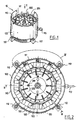
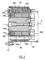
- FIGS. 1 to 4 show a synchronous motor 10 according to the invention, comprising a stator 100 and a rotor 200.
- the motor 10 is brushless, with a flux concentration rotor and with a stator wound on teeth, and operates in three-phase current.
- the stator 100 comprises a housing 110 made of steel, having a side opening 111 for the passage including the electrical conductors for supplying the stator windings.
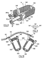
- the casing is externally provided with fixing lugs 112 and a lifting hook 113.
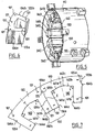
- the stator 100 comprises a magnetic circuit comprising, in the example shown, a plurality of identical sectors 120, one of which is shown separately in perspective in FIG.
- Each sector 120 is constituted by a bundle of identical magnetic sheets superimposed and clipped together so as to constitute a unitary unit, the clipping being obtained according to a technique known in itself by means of point deformations of each sheet at several points. 121.
- the use of a magnetic sheet package makes it possible to limit the losses due to induced currents.
- the magnetic circuit of the stator could be formed by the superposition of sheets, each of generally annular shape, into which all the teeth 130 of the stator would be cut.
- the sectors could have several teeth each. Two sectors 120 form, when assembled, a tooth 130 of non-constant width, used to mount an individual coil 340, as can be seen in Figure 5 in particular.
- n teeth is in the example described equal to 12, the motor being intended to be supplied with three-phase current and the rotor having 8 poles.
- the number of rotor poles could be different and in particular be equal to 12 or 16 for example.
- Each sector 120 comprises, on its sides 123a and 123b intended to cooperate with the adjacent sectors 120, respective reliefs 124a and 124b.
- These reliefs 124a and 124b have complementary shapes, with a generally triangular profile in plan view, one recessed the other projecting, with two substantially straight sides connected by a rounded. The cooperation of the reliefs 124a and 124b contributes to the good positioning of the sectors 120 between them during the assembly of the magnetic circuit of the stator.
- Each sector 120 also has, on its sides 123a and 123b, respective grooves 125a and 125b, each of semi-circular cross section, situated in the vicinity of the reliefs 124a and 124b, and forming holes 125 of circular section when the sectors 120 are assembled. These holes 125 are used to mount three detectors 190, as will be specified in the following.
- the gap E at the interface between two sectors 120 adjacent passes through the middle of the corresponding tooth 130, which reduces the magnetic losses since the magnetic flux can flow without encountering an air gap of a half tooth to the adjacent half tooth of the same sector 120, during operation of the machine.
- the sectors can be made with cut elements practically without falling with tools of relatively small size, so capable of high rates.
- the set of sectors 120 is force-fitted into the cylindrical casing 110 and the cohesion of the magnetic circuit formed by all the sectors 120 is provided by the radial compression forces exerted by the casing 110 on the sectors 120, the dif- the support of the sectors between them being relatively large.
- Each sector 120 defines a notch 140 whose opposite sides 141a and 141b each make an angle of more than 90 ° with the adjacent regions 142a and 142b of the bottom of the notch 140, themselves perpendicular to the radii passing through the line of connection of the concerned tooth with the bottom of the notch.
- the angle i is 90.4 °, this value being of course only an example.
- the sides 123a and 123b of the sectors are generally each aligned with a radius, except the reliefs 124a, 124b, 125a and 125b, and the width of each tooth 130 increases significantly, except for cutouts 144a or 144b made near its free end 131 turned towards the rotor, as one moves away from the rotor.
- each tooth 130 does not have, in the vicinity of its free end 131, pole shoes, unlike a large number of known stators which have semi-closed notches.
- the end portions 132a and 132b of each tooth 130, located between its free end 131 and the cutouts 144a or 144b, are aligned with the sides 141a and 141b, respectively.
- the free end 131 is a cylindrical portion of revolution, of the same axis as the axis of rotation of the rotor, and concave towards the rotor.
- each notch has a median region 142c connecting the regions 142a and 142b and perpendicular to a radius intersecting the notch 140 at mid-width, shown in broken lines in FIG. 7.
- each tooth 130 receives an individual coil 340, occupying in each notch 140 adjacent to the tooth 130 considered, substantially half the volume of this notch.
- an individual coil 340 is shown separately. This coil is formed by the winding around a winding geometric axis W of a bundle 341 of enamelled electric wires 342, this bundle being substantially flat in section. cross-section, as can be seen in Figure 9.
- the beam 341 comprises about ten individual conductors 342, each of circular section.
- the beam 341 forms about twenty turns 343 superimposed.
- the conductors 342 are electrically insulated from each other at the turns by the use of enamelled wire.
- the conductors 342 are stripped at their ends to form electrical connection ends 344a and 344b, each curved hook-shaped towards a median plane of the coil, perpendicular to the winding axis W. These hooks, at the end of the manufacturing process of the coil, are open towards the body of it.
- the inner section of the coil 340 has a generally rectangular shape, as can be seen in FIG. 10.
- the coils 340 are wound on shapes having two large opposite planar faces forming between them the same angle as the sides 141a and 141b. a tooth, so that the width of the inner section of each coil varies substantially from one end face to the opposite face. This can be seen by trying to mount a coil upside down on a tooth 130 of the stator 100.
- the coils 340 are electrically connected by an electrical connection end 344a or 344b to electrical conductors sheathed 150, partially stripped, before being mounted on the teeth 130 of the stator 100.
- the hooks formed by the ends 344a and 344b are for example arranged to substantially match the outer diameter of the electrical conductors 150 in the stripped portions 151.
- These stripped portions may be formed not only at the ends of the electrical conductors 150 but also between them, by removal over a limited length of the plastic insulating sheath.
- two coils 340 are formed which are then mounted on the corresponding teeth 130, as illustrated in FIG. 11.
- Insulating sheets 349 are interposed between the teeth and the bottom of the notches and the coils. . The ends of these sheets 349 can be seen in Figures 5 and 11.
- wedges 160 comprise, as can be seen in FIG. partitions 161 extending between the parts of the two coils 340 housed in the notch 140 concerned.
- the cables 150 extend along substantially circular paths on one side of the magnetic circuit of the stator, behind the free ends 131 of the teeth, as represented in FIG. 12, these cables being attached to each other by collars, and the impregnation of the stator with an insulating resin, conventionally.
- the precise electrical connection diagram of the twelve coils with each other is given in Figure 20, but it is only an example.
- the convergence of the sides 141a and 141b of the tooth 130 to the rotor and the corresponding shape of the section inside the coil contribute to its immobilization on the tooth 130.
- the repair can be done on the spot, without having to return the machine to the manufacturer, and without having to re-impregnate the stator, which makes it possible to shorten the repair time.
- the motor 10 may advantageously be delivered with one or more replacement coils 340.
- the rotor 200 will now be described with reference to FIGS. 13 to 18.
- the latter comprises a non-magnetic shaft 210, shown in isolation in front view in FIG. 15, comprising a central portion 211, of generally annular shape, and its periphery a plurality of ribs 220 for fastening pole pieces 230 each constituted by a stack of identical magnetic sheets superimposed and clipped.
- the use of superimposed magnetic sheets makes it possible to reduce the induced current losses.
- the ribs 220 have a generally T-shaped cross section.
- the pole pieces 230 are not connected magnetically to one another, given the use of a non-magnetic material to make the shaft.
- a pole piece 230 in FIG. 16 is shown separately in plan view.
- Each pole piece 230 has a cutout 250 having a shape adapted to engage a rib 220, by sliding parallel to the axis of rotation of the rib. rotor.
- the ribs 220 are made in one piece with the central portion 211, aluminum, by machining in the example, but other techniques such as wire drawing or injection could be used. It will be noted that the pole pieces 230, in the example described, are not engaged on anything other than the ribs of the shaft.
- the ribs 220 could be replaced by inserted bars, made integral with end flanges, when the rotor is relatively short or is not intended to rotate at a high speed, as will be explained later.
- the cutout 250 is symmetrical with respect to a median plane passing through its middle and containing a radius. It comprises a bottom 251 which is intended to come into contact with the radially outer face 221 of the corresponding rib 220.
- the bottom 251 is connected to opposite sides 252, each having a first rounded portion 252a, of radius of curvature R a , a straight oblique intermediate portion 252b making a non-zero angle ii with the radius passing through the middle of the bottom 251 and a second rounded portion 252c, of radius of curvature R c .
- R a is 3 mm
- R c is 5 mm
- the angle ii is 70 °.
- the cutout 250 has a narrowed opening, which allows attachment to a rib 220.
- each rib 220 is substantially complementary to that of the cutout 252, except for the presence of a chamfer 221a bordering the radially outer face 221 of the rib 220.
- Each side 222 of the rib thus comprises a rounded portion 222a having the same radius of curvature R a as the rounded portion 252a, a rectilinear portion 222b parallel to the portion 252b when the pole piece 230 is in place on the shaft 210 and a rounded portion 222c having the same radius of curvature R c that part 252c.
- the radially inner edges 233 of the pole piece 230 located on either side of the notch 250, extend back from the regions 213 of the shaft 210 situated between the ribs 220, as can be seen on the Figures 17 and 18 in particular.
- a free space 260 is thus formed between two adjacent ribs 220, the pole pieces 230 engaged on these ribs and the shaft 210.
- Permanent magnets 270 of slightly trapezoidal section are arranged radially, being inserted between the pole pieces 230, as shown in FIG. 18.
- Each magnet 270 has, when observed along the axis of rotation of the rotor, a slightly wedge shape, its width decreasing going radially outwards.
- Each magnet 270 which has a transverse magnetization may be monoblock or consist of several magnetic elements placed end to end. The magnetic poles of the same polarity of two adjacent magnets 270 are directed towards the pole piece 230 situated between these magnets 270, as illustrated in FIG. 18.
- each magnet 270 is constituted by three magnetic elements 270a, 270b and 270c placed end to end in the direction of the axis X of rotation of the rotor, as can be seen in Figure 3.
- the magnets 270 extend over substantially the entire radial dimension of the sides 238 of the rotor pole pieces 230 and their contact.
- the angle between the opposite planar faces of the magnets 270 coming into contact with the pole pieces 230 is relatively small, by a few degrees.
- the angle iii between the side 238 of a pole piece 230 and the adjacent edge 233 is equal in the example shown in FIG. 16 at 92.4 °.
- the radially outer side 235 of a pole piece 230 is of circular cross section, of radius of curvature less than the maximum radius of the rotor, so that each pole piece 230 has an outer face 235 which forms a slightly convex lobe outwardly, as can be seen in Figure 18.
- the curved shape of the pole pieces 230 reduces the torque ripple and create a cooling air stream.
- the housings formed between the pole pieces 230, and in which the magnets 270 are placed, tend to widen under the effect of the centrifugal force when the rotor 200 rotates at a speed greater than a predetermined speed, taking into account the elasticity of the materials used, this enlargement tends to decrease when the speed of rotation decreases.
- the magnets 270 have a radial dimension chosen so that when they are placed in the corresponding housing of the rotor, their radially outer end is set back from the radially outer edge, adjacent to the magnets, of the pole pieces.
- the magnets 270 are arranged to engage in the intervals formed by the widening of the aforementioned housings when the rotor rotates at a speed greater than said predetermined speed, so that the pole pieces 230 enclose the magnets 270 when the rotor speed drops back down. below said predetermined speed.
- the presence of the spaces 260 facilitates the placement of the magnets 270. It is understood that this provides a simple and effective means for securing the magnets 270 to the pole pieces 230.
- the magnet can be rotated. rotor 200 at a speed for example 10% greater than its nominal rotational speed, or even at a speed greater than 20% thereof.
- the magnets 270 are easily put in place, since it is not necessary to initially insert them between the pole pieces 230 with a large force, the final positioning of the magnets 270 taking place of itself when the rotor 200 is rotated. In addition, by rotating the rotor more or less quickly, it is possible, if necessary, to obtain a greater or lesser displacement of the pole pieces 230 and the magnets 270 and to act slightly on the outside diameter of the rotor. This can make it possible to produce the magnets 270 and the pole pieces 230, as well as the stator 100, with wider manufacturing tolerances, since it is possible to adjust the external diameter of the rotor 200 to a desired value by rotating it. more or less quickly.
- the magnets 270 have a low electrical resistivity, but are not subjected to heating risk of demagnetizing through the protection conferred vis-à-vis the pulsating flow by the pole pieces 230 at high speeds.
- the wedge shape of the magnets 270 makes it possible to exert on the parts polar parts 230 which enclose the ribs 220 of the compressive forces which tend to close the cutouts 250 on the ribs 220, and all the more so as the speed is high. , so that the whole is self-blocking.
- the above-mentioned compressive forces make it possible to reduce the width of the parts of the pole pieces located on either side of a rib, thus to benefit from a greater width at the connection of the rib to the shaft and to use to achieve the latter a less mechanically resistant material than nonmagnetic steel, but less expensive and lighter, such as aluminum.
- End cheeks 280 and 290 are fixed on the shaft 210 on either side thereof, for axially locking the pole pieces 230 and the magnets 270 as needed. These flanges define a stage of the machine .
- the rotor 200 may comprise several stages separated by intermediate cheeks and the number of magnets 270 per stage may be for example between 4 and 64, which can be equal to 8 as in the example shown for an 8-pole motor. When several stages are used and are separated by intermediate cheeks, the number of cheeks will preferably be equal to the number of stages plus one.
- the cheeks 280, 290 may be made for example of aluminum or non-magnetic steel.
- the cheeks 280 and 290 are fixed on the shaft 210 by means of bolts 281.
- Tapped holes 500 are made on the cheeks 280, 290, at their periphery, to allow the fixing of balancing screws.
- the flange 280 has a radially outer edge 282 circular, set back from the radially outer edge 235 of the pole pieces 230 and the radially outer edge of the magnets 270, which is substantially at the level of ends 235a of the curved faces.
- An annular zone A is thus formed around cheek 280, enabling the magnetic field of magnets 270 of the rotor to be read by means of detectors 190 that can be seen in FIG. 4. It can be seen in FIG. 4 that detectors 190 may slightly cover the rotor 200, thanks to the recessed positioning of the cheek 280.
- the detectors 190 are, in the example described, the number of three, the motor being three-phase, and each comprise a Hall effect sensor arranged to detect the magnetic field above the peripheral region A of the rotor 200, around of the cheek 280. The magnetic field is read along an axis parallel to the axis of rotation of the rotor, the Hall effect sensor overlapping the peripheral region A.
- the detectors 190 are mounted in the illustrated example on three consecutive teeth 130 located in the vicinity of the hearing 111.
- Each detector 190 is fixed by a screw 191 on a tooth 130 of the stator, this screw 191 being engaged in a hole 125.
- Each detector 190 extends along the radial axis Z u , Z v or Z w of the associated tooth and crosses the coil 340 engaged on this tooth.
- the coils 340 have for this purpose an inner section whose length is large enough to allow the passage of the detector 190.
- the space between a coil and the corresponding tooth for the passage of the detector may be of the order of 5 mm, for example, such a space to isolate the coil and the tooth where there is no insulation 349.
- the direct reading of the magnetic field of the permanent magnets 270 is advantageous because it makes it possible to avoid having to relate to the rotor specific elements serving only to read the angular position of the rotor.
- the manufacture of the rotor is simplified and increased reliability.
- the mounting of the detectors 190 in the space between the coils 340 and the teeth 130 is particularly compact, while allowing easy access to the detectors 190 to replace them, if necessary.
- Each detector 190 is positioned within a given phase coil 340 (u, v and w). Each detector 190 makes it possible to detect which polarity of the rotor is in front of the associated coil (and therefore of the phase concerned) at a given instant. Each detector 190 delivers a low or high signal according to the detected polarity. Each detector 190 comprises an electronic circuit for shaping the signals delivered by the Hall effect sensor, in order to reduce the sensitivity to the parasites. Depending on the position of the rotor, there are six possible combinations of the different signals delivered by the detectors 190, and each change of triplet constituted by the states of the detectors 190 corresponding to a determined angular position of the rotor.
- Each detector 190 further comprises a temperature sensor.
- the rotor 200 comprises, on at least one of the flanges 280 and 290, cooling fins 291, visible in FIG. 1 in particular. It will be noted that an additional cooling action is obtained thanks to the presence of the lobes 235 formed by the pole pieces 230 at the periphery of the rotor, which make it possible to generate a cooling air stream at the very heart of the engine.
- the invention makes it possible, for example, to manufacture electrical rotating machines from a range of magnetic circuits of stators and prefabricated rotors, of different diameters, the stators having standard teeth.
- the axial dimensions of the magnetic circuits of the rotor and the stator will be chosen as a function of the power to be supplied, by stacking a greater or lesser number of sectors and pole pieces.
- Only the coils can for example be custom made for a stator magnetic circuit made from prefabricated elements, by determining the number of turns of the coil, the diameter of the conductive wires of the flat bundle and the number of these wires, in depending on the performance demanded by the user of the machine.
- the invention is not limited to a synchronous motor and also applies to a generator.
- the rotor can be inside or outside.
- the electrical power of the machine can be for example between 1 and 750 kW.
- the rotational speed of the rotor may be for example between 1000 and 10 000 rpm.
- a machine according to the invention can also find applications when the speed is less than 1000 rpm.
- the outer diameter of the machine may be for example between 50 mm and 1 m; in the most common applications, the outside diameter may be between 100 and 600 mm.
- the invention is not limited to a particular number of poles or the supply of the stator with three-phase current.
- the current can be polyphase with n phase phases, n different from three.
- the shaft can be made of other non-magnetic materials than aluminum, for example aluminum alloys.
- the stator teeth may have a face facing the rotor other than cylindrical of revolution about the axis of the rotor.
- the notches could be semi-closed.
- the pole pieces 230 ' are stacked on bars 220', held by end flanges integral with the shaft, as shown in FIG. 20.
- the magnets 270 ' which have a wedge shape, are arranged between the pole pieces 230 'engaged on the bars 220'.
- the pole pieces may include a recess, as shown in Figure 21, to retain the magnets 270 'before centrifugation.
Landscapes
- Engineering & Computer Science (AREA)
- Power Engineering (AREA)
- Microelectronics & Electronic Packaging (AREA)
- Mechanical Engineering (AREA)
- Iron Core Of Rotating Electric Machines (AREA)
- Synchronous Machinery (AREA)
- Permanent Field Magnets Of Synchronous Machinery (AREA)
- Permanent Magnet Type Synchronous Machine (AREA)
Applications Claiming Priority (5)
| Application Number | Priority Date | Filing Date | Title |
|---|---|---|---|
| FR0005639A FR2808627B1 (fr) | 2000-05-03 | 2000-05-03 | Rotor de machine tournante electrique et procede de fabrication |
| FR0005639 | 2000-05-03 | ||
| FR0102263 | 2001-02-20 | ||
| FR0102263A FR2821023A1 (fr) | 2001-02-20 | 2001-02-20 | Roue motrice a moteur synchrone |
| EP01400981A EP1152516B1 (fr) | 2000-05-03 | 2001-04-17 | Machine tournante électrique à rotor à concentration de flux et à stator bobiné sur dents |
Related Parent Applications (2)
| Application Number | Title | Priority Date | Filing Date |
|---|---|---|---|
| EP01400981.5 Division | 2001-04-17 | ||
| EP01400981A Division EP1152516B1 (fr) | 2000-05-03 | 2001-04-17 | Machine tournante électrique à rotor à concentration de flux et à stator bobiné sur dents |
Publications (2)
| Publication Number | Publication Date |
|---|---|
| EP1249919A1 EP1249919A1 (fr) | 2002-10-16 |
| EP1249919B1 true EP1249919B1 (fr) | 2006-03-15 |
Family
ID=26212373
Family Applications (2)
| Application Number | Title | Priority Date | Filing Date |
|---|---|---|---|
| EP02291384A Expired - Lifetime EP1249919B1 (fr) | 2000-05-03 | 2001-04-17 | Rotor de machine electrique tournante |
| EP01400981A Expired - Lifetime EP1152516B1 (fr) | 2000-05-03 | 2001-04-17 | Machine tournante électrique à rotor à concentration de flux et à stator bobiné sur dents |
Family Applications After (1)
| Application Number | Title | Priority Date | Filing Date |
|---|---|---|---|
| EP01400981A Expired - Lifetime EP1152516B1 (fr) | 2000-05-03 | 2001-04-17 | Machine tournante électrique à rotor à concentration de flux et à stator bobiné sur dents |
Country Status (4)
| Country | Link |
|---|---|
| EP (2) | EP1249919B1 (es) |
| AT (2) | ATE320674T1 (es) |
| DE (3) | DE60100046T2 (es) |
| ES (2) | ES2186664T3 (es) |
Cited By (2)
| Publication number | Priority date | Publication date | Assignee | Title |
|---|---|---|---|---|
| CN101608393A (zh) * | 2009-07-20 | 2009-12-23 | 叶露微 | 一种家用离心式脱水机 |
| DE102021117625A1 (de) | 2021-07-08 | 2023-01-12 | Knorr-Bremse Systeme für Nutzfahrzeuge GmbH | Permanenterregte Elektromaschine |
Families Citing this family (18)
| Publication number | Priority date | Publication date | Assignee | Title |
|---|---|---|---|---|
| US6700288B2 (en) | 2001-08-15 | 2004-03-02 | Drs Power & Control Technologies, Inc. | High speed rotor |
| DE20122394U1 (de) * | 2001-12-22 | 2005-06-23 | Grundfos A/S | Stator eines Elektromotors |
| WO2003073583A1 (de) * | 2002-02-28 | 2003-09-04 | Abb Research Ltd. | Synchrongenerator |
| FR2852162B1 (fr) | 2003-03-06 | 2005-09-23 | Leroy Somer Moteurs | Machine electrique tournante comportant un stator et deux rotors |
| FR2895844A1 (fr) | 2006-01-03 | 2007-07-06 | Leroy Somer Moteurs | Machine electrique tournante comportant des pieces polaires et des aimants permanents |
| KR101225971B1 (ko) * | 2006-04-07 | 2013-01-24 | 엘지전자 주식회사 | 모터 및 그를 갖는 공기조화기 |
| WO2007117078A2 (en) * | 2006-04-07 | 2007-10-18 | Lg Electronics Inc. | Air conditioner and motor of air conditioner |
| FR2903824A1 (fr) * | 2006-07-13 | 2008-01-18 | Leroy Somer Moteurs | Rotor de machine tournante electrique et procede de fabrication |
| EP2066008B1 (de) * | 2007-11-29 | 2011-08-03 | Siemens Aktiengesellschaft | Stator einer dynamoelektrischen Maschine mit Mitteln zur Temperaturerfassung |
| FR2932618B1 (fr) * | 2008-06-16 | 2010-11-19 | Leroy Somer Moteurs | Rotor a aimants permanents et machine tournante comportant un tel rotor |
| JP5241769B2 (ja) | 2010-05-12 | 2013-07-17 | 三菱電機株式会社 | 電動式パワーステアリング装置用モータ |
| FR2976139B1 (fr) | 2011-05-31 | 2016-04-15 | Moteurs Leroy-Somer | Rotor a aimants permanents et machine tournante comportant un tel rotor. |
| KR101949198B1 (ko) * | 2011-09-08 | 2019-02-20 | 삼성전자주식회사 | 모터와 이를 가지는 세탁기 |
| CN202334208U (zh) * | 2011-11-16 | 2012-07-11 | 宁波威士顿车业有限公司 | 自行车用轮毂发电机 |
| FR2983008B1 (fr) | 2011-11-18 | 2013-12-20 | Leroy Somer Moteurs | Rotor de machine electrique tournante a concentration de flux |
| FR2983007B1 (fr) | 2011-11-18 | 2015-03-06 | Leroy Somer Moteurs | Rotor de machine electrique tournante a aimants permanents. |
| ES2547454T3 (es) | 2013-04-15 | 2015-10-06 | Siemens Aktiengesellschaft | Máquina eléctrica con carcasa sobre una porción de su circunferencia |
| FR3105633B1 (fr) | 2019-12-20 | 2022-06-24 | Nidec Psa Emotors | Rotor de machine electrique tournante |
Family Cites Families (10)
| Publication number | Priority date | Publication date | Assignee | Title |
|---|---|---|---|---|
| US4339874A (en) * | 1978-12-26 | 1982-07-20 | The Garrett Corporation | Method of making a wedge-shaped permanent magnet rotor assembly |
| JPH01278247A (ja) * | 1988-04-30 | 1989-11-08 | Fanuc Ltd | 同期電動機 |
| JPH0332333A (ja) * | 1989-06-26 | 1991-02-12 | Fanuc Ltd | ラジアルタイプのロータ構造 |
| FR2655214B1 (fr) * | 1989-11-27 | 1992-02-07 | Alsthom Gec | Rotor de moteur a aimants. |
| FR2655784B1 (fr) * | 1989-12-08 | 1992-01-24 | Alsthom Gec | Moteur a aimants a concentration de flux. |
| JP3690616B2 (ja) * | 1996-04-15 | 2005-08-31 | 日立金属株式会社 | 回転機 |
| US5952755A (en) * | 1997-03-18 | 1999-09-14 | Electric Boat Corporation | Permanent magnet motor rotor |
| TW380329B (en) * | 1997-04-16 | 2000-01-21 | Japan Servo | Permanent-magnet revolving electrodynamic machine with a concentrated winding stator |
| FR2784815B1 (fr) * | 1998-10-20 | 2001-06-08 | Valeo Equip Electr Moteur | Machine electrique tournante, en particulier alternateur de vehicule automobile, possedant des moyens perfectionnes de reduction de bruit |
| ES2257837T3 (es) * | 1998-11-13 | 2006-08-01 | Conception Et Developpement Michelin | Maquina electrica cuyo rotor esta especialmente adaptado a las altas velocidades. |
-
2001
- 2001-04-17 DE DE60100046T patent/DE60100046T2/de not_active Expired - Lifetime
- 2001-04-17 EP EP02291384A patent/EP1249919B1/fr not_active Expired - Lifetime
- 2001-04-17 DE DE20107523U patent/DE20107523U1/de not_active Expired - Lifetime
- 2001-04-17 ES ES01400981T patent/ES2186664T3/es not_active Expired - Lifetime
- 2001-04-17 AT AT02291384T patent/ATE320674T1/de not_active IP Right Cessation
- 2001-04-17 AT AT01400981T patent/ATE227898T1/de not_active IP Right Cessation
- 2001-04-17 EP EP01400981A patent/EP1152516B1/fr not_active Expired - Lifetime
- 2001-04-17 DE DE60118044T patent/DE60118044T2/de not_active Expired - Lifetime
- 2001-04-17 ES ES02291384T patent/ES2258603T3/es not_active Expired - Lifetime
Cited By (3)
| Publication number | Priority date | Publication date | Assignee | Title |
|---|---|---|---|---|
| CN101608393A (zh) * | 2009-07-20 | 2009-12-23 | 叶露微 | 一种家用离心式脱水机 |
| CN101608393B (zh) * | 2009-07-20 | 2013-03-27 | 江门金羚电机有限公司 | 一种家用离心式脱水机 |
| DE102021117625A1 (de) | 2021-07-08 | 2023-01-12 | Knorr-Bremse Systeme für Nutzfahrzeuge GmbH | Permanenterregte Elektromaschine |
Also Published As
| Publication number | Publication date |
|---|---|
| EP1152516A3 (fr) | 2001-12-05 |
| ES2186664T3 (es) | 2003-05-16 |
| DE60118044T2 (de) | 2006-11-16 |
| DE60100046D1 (de) | 2002-12-19 |
| EP1249919A1 (fr) | 2002-10-16 |
| EP1152516B1 (fr) | 2002-11-13 |
| ATE227898T1 (de) | 2002-11-15 |
| DE60118044D1 (de) | 2006-05-11 |
| DE60100046T2 (de) | 2003-08-21 |
| ATE320674T1 (de) | 2006-04-15 |
| EP1152516A2 (fr) | 2001-11-07 |
| DE20107523U1 (de) | 2001-07-12 |
| ES2258603T3 (es) | 2006-09-01 |
Similar Documents
| Publication | Publication Date | Title |
|---|---|---|
| EP1251629B1 (fr) | Machine électrique comportant au moins un détecteur de champ magnétique | |
| EP1249919B1 (fr) | Rotor de machine electrique tournante | |
| EP1251620B1 (fr) | Machine tournante électrique comportant un stator formé de secteurs assemblés | |
| EP1251623A1 (fr) | Stator de machine tournante électrique comportant des bobines individuelles démontables | |
| WO2004082100A2 (fr) | Machine electrique tournante comportant un stator et deux rotors | |
| FR2852461A1 (fr) | Stator pour machine dynamo-electriques | |
| EP1251622B1 (fr) | Bobine pour machine électrique tournante | |
| FR3054746A1 (fr) | Machine electrique tournante munie d'un interconnecteur dote de bequilles d'appui | |
| WO2014174200A2 (fr) | Élément isolant muni de crochets de maintien de fils de bobinage d'un stator de machine électrique et stator correspondant | |
| FR3103649A1 (fr) | Stator de machine électrique tournante avec bobinage asymétrique | |
| EP3811505A1 (fr) | Machine électrique tournante ayant une configuration de rotor réduisant les ondulations de couple | |
| WO2020174190A1 (fr) | Stator de machine electrique tournante | |
| EP3259830B1 (fr) | Rotor de machine électrique tournante a aimants permanents segmentes | |
| FR2906942A1 (fr) | Rotor a griffes muni d'elements ferromagnetiques interpolaires de largeur optimisee et machine tournante equipe d'un tel rotor | |
| EP3895294B1 (fr) | Rotor à arbre non traversant et machine électrique tournante associée | |
| FR3053543A1 (fr) | Machine electrique tournante munie d'un interconnecteur fixe sur le corps du stator | |
| FR3054748B1 (fr) | Machine electrique tournante munie d'un interconnecteur a traces de couplage empilees radialement | |
| EP3107193B1 (fr) | Rotor à tôles empilées | |
| FR3086118A1 (fr) | Machine electrique tournante munie d'un rotor a masse reduite | |
| FR3093385A1 (fr) | Stator de machine électrique tournante | |
| EP3607640A1 (fr) | Rotor pour machine électrique à aimants permanents internes | |
| FR2802724A1 (fr) | Stator a dents convexes | |
| FR3054747B1 (fr) | Machine electrique tournante munie d'un bobinage a configuration amelioree | |
| WO2021064315A1 (fr) | Rotor de machine electrique tournante | |
| WO2008026032A1 (fr) | Machine electrique a stator muni de griffes et de bobinages deportes |
Legal Events
| Date | Code | Title | Description |
|---|---|---|---|
| PUAI | Public reference made under article 153(3) epc to a published international application that has entered the european phase |
Free format text: ORIGINAL CODE: 0009012 |
|
| AC | Divisional application: reference to earlier application |
Ref document number: 1152516 Country of ref document: EP |
|
| AK | Designated contracting states |
Kind code of ref document: A1 Designated state(s): AT BE CH CY DE DK ES FI FR GB GR IE IT LI LU MC NL PT SE TR |
|
| AX | Request for extension of the european patent |
Free format text: AL;LT;LV;MK;RO;SI |
|
| 17P | Request for examination filed |
Effective date: 20021129 |
|
| AKX | Designation fees paid |
Designated state(s): AT BE CH CY DE DK ES FI FR GB GR IE IT LI LU MC NL PT SE TR |
|
| GRAP | Despatch of communication of intention to grant a patent |
Free format text: ORIGINAL CODE: EPIDOSNIGR1 |
|
| GRAS | Grant fee paid |
Free format text: ORIGINAL CODE: EPIDOSNIGR3 |
|
| GRAA | (expected) grant |
Free format text: ORIGINAL CODE: 0009210 |
|
| AC | Divisional application: reference to earlier application |
Ref document number: 1152516 Country of ref document: EP Kind code of ref document: P |
|
| AK | Designated contracting states |
Kind code of ref document: B1 Designated state(s): AT BE CH CY DE DK ES FI FR GB GR IE IT LI LU MC NL PT SE TR |
|
| PG25 | Lapsed in a contracting state [announced via postgrant information from national office to epo] |
Ref country code: NL Free format text: LAPSE BECAUSE OF FAILURE TO SUBMIT A TRANSLATION OF THE DESCRIPTION OR TO PAY THE FEE WITHIN THE PRESCRIBED TIME-LIMIT Effective date: 20060315 Ref country code: FI Free format text: LAPSE BECAUSE OF FAILURE TO SUBMIT A TRANSLATION OF THE DESCRIPTION OR TO PAY THE FEE WITHIN THE PRESCRIBED TIME-LIMIT Effective date: 20060315 Ref country code: IE Free format text: LAPSE BECAUSE OF FAILURE TO SUBMIT A TRANSLATION OF THE DESCRIPTION OR TO PAY THE FEE WITHIN THE PRESCRIBED TIME-LIMIT Effective date: 20060315 Ref country code: AT Free format text: LAPSE BECAUSE OF FAILURE TO SUBMIT A TRANSLATION OF THE DESCRIPTION OR TO PAY THE FEE WITHIN THE PRESCRIBED TIME-LIMIT Effective date: 20060315 |
|
| REG | Reference to a national code |
Ref country code: GB Ref legal event code: FG4D Free format text: NOT ENGLISH Ref country code: CH Ref legal event code: EP |
|
| REG | Reference to a national code |
Ref country code: IE Ref legal event code: FG4D Free format text: LANGUAGE OF EP DOCUMENT: FRENCH |
|
| PG25 | Lapsed in a contracting state [announced via postgrant information from national office to epo] |
Ref country code: BE Free format text: LAPSE BECAUSE OF NON-PAYMENT OF DUE FEES Effective date: 20060430 Ref country code: LI Free format text: LAPSE BECAUSE OF NON-PAYMENT OF DUE FEES Effective date: 20060430 Ref country code: CH Free format text: LAPSE BECAUSE OF NON-PAYMENT OF DUE FEES Effective date: 20060430 Ref country code: MC Free format text: LAPSE BECAUSE OF NON-PAYMENT OF DUE FEES Effective date: 20060430 |
|
| REF | Corresponds to: |
Ref document number: 60118044 Country of ref document: DE Date of ref document: 20060511 Kind code of ref document: P |
|
| GBT | Gb: translation of ep patent filed (gb section 77(6)(a)/1977) |
Effective date: 20060426 |
|
| PG25 | Lapsed in a contracting state [announced via postgrant information from national office to epo] |
Ref country code: SE Free format text: LAPSE BECAUSE OF FAILURE TO SUBMIT A TRANSLATION OF THE DESCRIPTION OR TO PAY THE FEE WITHIN THE PRESCRIBED TIME-LIMIT Effective date: 20060615 Ref country code: DK Free format text: LAPSE BECAUSE OF FAILURE TO SUBMIT A TRANSLATION OF THE DESCRIPTION OR TO PAY THE FEE WITHIN THE PRESCRIBED TIME-LIMIT Effective date: 20060615 |
|
| PG25 | Lapsed in a contracting state [announced via postgrant information from national office to epo] |
Ref country code: PT Free format text: LAPSE BECAUSE OF FAILURE TO SUBMIT A TRANSLATION OF THE DESCRIPTION OR TO PAY THE FEE WITHIN THE PRESCRIBED TIME-LIMIT Effective date: 20060816 |
|
| NLV1 | Nl: lapsed or annulled due to failure to fulfill the requirements of art. 29p and 29m of the patents act | ||
| REG | Reference to a national code |
Ref country code: ES Ref legal event code: FG2A Ref document number: 2258603 Country of ref document: ES Kind code of ref document: T3 |
|
| REG | Reference to a national code |
Ref country code: IE Ref legal event code: FD4D |
|
| REG | Reference to a national code |
Ref country code: CH Ref legal event code: PL |
|
| PLBE | No opposition filed within time limit |
Free format text: ORIGINAL CODE: 0009261 |
|
| STAA | Information on the status of an ep patent application or granted ep patent |
Free format text: STATUS: NO OPPOSITION FILED WITHIN TIME LIMIT |
|
| 26N | No opposition filed |
Effective date: 20061218 |
|
| BERE | Be: lapsed |
Owner name: MOTEURS LEROY-SOMER Effective date: 20060430 |
|
| PG25 | Lapsed in a contracting state [announced via postgrant information from national office to epo] |
Ref country code: GR Free format text: LAPSE BECAUSE OF FAILURE TO SUBMIT A TRANSLATION OF THE DESCRIPTION OR TO PAY THE FEE WITHIN THE PRESCRIBED TIME-LIMIT Effective date: 20060616 |
|
| PG25 | Lapsed in a contracting state [announced via postgrant information from national office to epo] |
Ref country code: TR Free format text: LAPSE BECAUSE OF FAILURE TO SUBMIT A TRANSLATION OF THE DESCRIPTION OR TO PAY THE FEE WITHIN THE PRESCRIBED TIME-LIMIT Effective date: 20060315 Ref country code: LU Free format text: LAPSE BECAUSE OF NON-PAYMENT OF DUE FEES Effective date: 20060417 |
|
| PG25 | Lapsed in a contracting state [announced via postgrant information from national office to epo] |
Ref country code: CY Free format text: LAPSE BECAUSE OF FAILURE TO SUBMIT A TRANSLATION OF THE DESCRIPTION OR TO PAY THE FEE WITHIN THE PRESCRIBED TIME-LIMIT Effective date: 20060315 |
|
| PGFP | Annual fee paid to national office [announced via postgrant information from national office to epo] |
Ref country code: DE Payment date: 20120626 Year of fee payment: 12 |
|
| PGFP | Annual fee paid to national office [announced via postgrant information from national office to epo] |
Ref country code: GB Payment date: 20120420 Year of fee payment: 12 Ref country code: FR Payment date: 20120529 Year of fee payment: 12 |
|
| PGFP | Annual fee paid to national office [announced via postgrant information from national office to epo] |
Ref country code: IT Payment date: 20120426 Year of fee payment: 12 |
|
| PGFP | Annual fee paid to national office [announced via postgrant information from national office to epo] |
Ref country code: ES Payment date: 20120416 Year of fee payment: 12 |
|
| GBPC | Gb: european patent ceased through non-payment of renewal fee |
Effective date: 20130417 |
|
| PG25 | Lapsed in a contracting state [announced via postgrant information from national office to epo] |
Ref country code: GB Free format text: LAPSE BECAUSE OF NON-PAYMENT OF DUE FEES Effective date: 20130417 Ref country code: DE Free format text: LAPSE BECAUSE OF NON-PAYMENT OF DUE FEES Effective date: 20131101 |
|
| REG | Reference to a national code |
Ref country code: FR Ref legal event code: ST Effective date: 20131231 |
|
| REG | Reference to a national code |
Ref country code: DE Ref legal event code: R119 Ref document number: 60118044 Country of ref document: DE Effective date: 20131101 |
|
| PG25 | Lapsed in a contracting state [announced via postgrant information from national office to epo] |
Ref country code: IT Free format text: LAPSE BECAUSE OF NON-PAYMENT OF DUE FEES Effective date: 20130417 Ref country code: FR Free format text: LAPSE BECAUSE OF NON-PAYMENT OF DUE FEES Effective date: 20130430 |
|
| REG | Reference to a national code |
Ref country code: ES Ref legal event code: FD2A Effective date: 20140606 |
|
| PG25 | Lapsed in a contracting state [announced via postgrant information from national office to epo] |
Ref country code: ES Free format text: LAPSE BECAUSE OF NON-PAYMENT OF DUE FEES Effective date: 20130418 |