EP1152516A2 - Machine tournante électrique à rotor à concentration de flux et à stator bobiné sur dents - Google Patents
Machine tournante électrique à rotor à concentration de flux et à stator bobiné sur dents Download PDFInfo
- Publication number
- EP1152516A2 EP1152516A2 EP01400981A EP01400981A EP1152516A2 EP 1152516 A2 EP1152516 A2 EP 1152516A2 EP 01400981 A EP01400981 A EP 01400981A EP 01400981 A EP01400981 A EP 01400981A EP 1152516 A2 EP1152516 A2 EP 1152516A2
- Authority
- EP
- European Patent Office
- Prior art keywords
- machine according
- rotor
- stator
- teeth
- magnets
- Prior art date
- Legal status (The legal status is an assumption and is not a legal conclusion. Google has not performed a legal analysis and makes no representation as to the accuracy of the status listed.)
- Granted
Links
Images


Classifications
-
- H—ELECTRICITY
- H02—GENERATION; CONVERSION OR DISTRIBUTION OF ELECTRIC POWER
- H02K—DYNAMO-ELECTRIC MACHINES
- H02K7/00—Arrangements for handling mechanical energy structurally associated with dynamo-electric machines, e.g. structural association with mechanical driving motors or auxiliary dynamo-electric machines
- H02K7/14—Structural association with mechanical loads, e.g. with hand-held machine tools or fans
-
- H—ELECTRICITY
- H02—GENERATION; CONVERSION OR DISTRIBUTION OF ELECTRIC POWER
- H02K—DYNAMO-ELECTRIC MACHINES
- H02K1/00—Details of the magnetic circuit
- H02K1/06—Details of the magnetic circuit characterised by the shape, form or construction
- H02K1/22—Rotating parts of the magnetic circuit
- H02K1/27—Rotor cores with permanent magnets
- H02K1/2786—Outer rotors
- H02K1/2787—Outer rotors the magnetisation axis of the magnets being perpendicular to the rotor axis
- H02K1/2789—Outer rotors the magnetisation axis of the magnets being perpendicular to the rotor axis the rotor consisting of two or more circumferentially positioned magnets
- H02K1/2791—Surface mounted magnets; Inset magnets
-
- B—PERFORMING OPERATIONS; TRANSPORTING
- B66—HOISTING; LIFTING; HAULING
- B66D—CAPSTANS; WINCHES; TACKLES, e.g. PULLEY BLOCKS; HOISTS
- B66D1/00—Rope, cable, or chain winding mechanisms; Capstans
- B66D1/02—Driving gear
- B66D1/12—Driving gear incorporating electric motors
-
- H—ELECTRICITY
- H02—GENERATION; CONVERSION OR DISTRIBUTION OF ELECTRIC POWER
- H02K—DYNAMO-ELECTRIC MACHINES
- H02K1/00—Details of the magnetic circuit
- H02K1/06—Details of the magnetic circuit characterised by the shape, form or construction
- H02K1/12—Stationary parts of the magnetic circuit
- H02K1/14—Stator cores with salient poles
- H02K1/141—Stator cores with salient poles consisting of C-shaped cores
-
- H—ELECTRICITY
- H02—GENERATION; CONVERSION OR DISTRIBUTION OF ELECTRIC POWER
- H02K—DYNAMO-ELECTRIC MACHINES
- H02K1/00—Details of the magnetic circuit
- H02K1/06—Details of the magnetic circuit characterised by the shape, form or construction
- H02K1/12—Stationary parts of the magnetic circuit
- H02K1/14—Stator cores with salient poles
- H02K1/146—Stator cores with salient poles consisting of a generally annular yoke with salient poles
-
- H—ELECTRICITY
- H02—GENERATION; CONVERSION OR DISTRIBUTION OF ELECTRIC POWER
- H02K—DYNAMO-ELECTRIC MACHINES
- H02K1/00—Details of the magnetic circuit
- H02K1/06—Details of the magnetic circuit characterised by the shape, form or construction
- H02K1/12—Stationary parts of the magnetic circuit
- H02K1/18—Means for mounting or fastening magnetic stationary parts on to, or to, the stator structures
- H02K1/185—Means for mounting or fastening magnetic stationary parts on to, or to, the stator structures to outer stators
-
- H—ELECTRICITY
- H02—GENERATION; CONVERSION OR DISTRIBUTION OF ELECTRIC POWER
- H02K—DYNAMO-ELECTRIC MACHINES
- H02K11/00—Structural association of dynamo-electric machines with electric components or with devices for shielding, monitoring or protection
- H02K11/20—Structural association of dynamo-electric machines with electric components or with devices for shielding, monitoring or protection for measuring, monitoring, testing, protecting or switching
- H02K11/25—Devices for sensing temperature, or actuated thereby
-
- H—ELECTRICITY
- H02—GENERATION; CONVERSION OR DISTRIBUTION OF ELECTRIC POWER
- H02K—DYNAMO-ELECTRIC MACHINES
- H02K21/00—Synchronous motors having permanent magnets; Synchronous generators having permanent magnets
- H02K21/12—Synchronous motors having permanent magnets; Synchronous generators having permanent magnets with stationary armatures and rotating magnets
- H02K21/14—Synchronous motors having permanent magnets; Synchronous generators having permanent magnets with stationary armatures and rotating magnets with magnets rotating within the armatures
- H02K21/16—Synchronous motors having permanent magnets; Synchronous generators having permanent magnets with stationary armatures and rotating magnets with magnets rotating within the armatures having annular armature cores with salient poles
-
- H—ELECTRICITY
- H02—GENERATION; CONVERSION OR DISTRIBUTION OF ELECTRIC POWER
- H02K—DYNAMO-ELECTRIC MACHINES
- H02K21/00—Synchronous motors having permanent magnets; Synchronous generators having permanent magnets
- H02K21/12—Synchronous motors having permanent magnets; Synchronous generators having permanent magnets with stationary armatures and rotating magnets
- H02K21/22—Synchronous motors having permanent magnets; Synchronous generators having permanent magnets with stationary armatures and rotating magnets with magnets rotating around the armatures, e.g. flywheel magnetos
-
- H—ELECTRICITY
- H02—GENERATION; CONVERSION OR DISTRIBUTION OF ELECTRIC POWER
- H02K—DYNAMO-ELECTRIC MACHINES
- H02K29/00—Motors or generators having non-mechanical commutating devices, e.g. discharge tubes or semiconductor devices
- H02K29/06—Motors or generators having non-mechanical commutating devices, e.g. discharge tubes or semiconductor devices with position sensing devices
- H02K29/08—Motors or generators having non-mechanical commutating devices, e.g. discharge tubes or semiconductor devices with position sensing devices using magnetic effect devices, e.g. Hall-plates, magneto-resistors
-
- H—ELECTRICITY
- H02—GENERATION; CONVERSION OR DISTRIBUTION OF ELECTRIC POWER
- H02K—DYNAMO-ELECTRIC MACHINES
- H02K3/00—Details of windings
- H02K3/04—Windings characterised by the conductor shape, form or construction, e.g. with bar conductors
- H02K3/18—Windings for salient poles
-
- H—ELECTRICITY
- H02—GENERATION; CONVERSION OR DISTRIBUTION OF ELECTRIC POWER
- H02K—DYNAMO-ELECTRIC MACHINES
- H02K3/00—Details of windings
- H02K3/04—Windings characterised by the conductor shape, form or construction, e.g. with bar conductors
- H02K3/28—Layout of windings or of connections between windings
-
- H—ELECTRICITY
- H02—GENERATION; CONVERSION OR DISTRIBUTION OF ELECTRIC POWER
- H02K—DYNAMO-ELECTRIC MACHINES
- H02K3/00—Details of windings
- H02K3/46—Fastening of windings on the stator or rotor structure
- H02K3/52—Fastening salient pole windings or connections thereto
- H02K3/521—Fastening salient pole windings or connections thereto applicable to stators only
- H02K3/522—Fastening salient pole windings or connections thereto applicable to stators only for generally annular cores with salient poles
-
- H—ELECTRICITY
- H02—GENERATION; CONVERSION OR DISTRIBUTION OF ELECTRIC POWER
- H02K—DYNAMO-ELECTRIC MACHINES
- H02K5/00—Casings; Enclosures; Supports
- H02K5/04—Casings or enclosures characterised by the shape, form or construction thereof
-
- H—ELECTRICITY
- H02—GENERATION; CONVERSION OR DISTRIBUTION OF ELECTRIC POWER
- H02K—DYNAMO-ELECTRIC MACHINES
- H02K7/00—Arrangements for handling mechanical energy structurally associated with dynamo-electric machines, e.g. structural association with mechanical driving motors or auxiliary dynamo-electric machines
- H02K7/10—Structural association with clutches, brakes, gears, pulleys or mechanical starters
- H02K7/1004—Structural association with clutches, brakes, gears, pulleys or mechanical starters with pulleys
- H02K7/1012—Machine arranged inside the pulley
- H02K7/1016—Machine of the outer rotor type
-
- H—ELECTRICITY
- H02—GENERATION; CONVERSION OR DISTRIBUTION OF ELECTRIC POWER
- H02K—DYNAMO-ELECTRIC MACHINES
- H02K7/00—Arrangements for handling mechanical energy structurally associated with dynamo-electric machines, e.g. structural association with mechanical driving motors or auxiliary dynamo-electric machines
- H02K7/10—Structural association with clutches, brakes, gears, pulleys or mechanical starters
- H02K7/102—Structural association with clutches, brakes, gears, pulleys or mechanical starters with friction brakes
- H02K7/1021—Magnetically influenced friction brakes
-
- H—ELECTRICITY
- H02—GENERATION; CONVERSION OR DISTRIBUTION OF ELECTRIC POWER
- H02K—DYNAMO-ELECTRIC MACHINES
- H02K7/00—Arrangements for handling mechanical energy structurally associated with dynamo-electric machines, e.g. structural association with mechanical driving motors or auxiliary dynamo-electric machines
- H02K7/10—Structural association with clutches, brakes, gears, pulleys or mechanical starters
- H02K7/116—Structural association with clutches, brakes, gears, pulleys or mechanical starters with gears
-
- B—PERFORMING OPERATIONS; TRANSPORTING
- B60—VEHICLES IN GENERAL
- B60K—ARRANGEMENT OR MOUNTING OF PROPULSION UNITS OR OF TRANSMISSIONS IN VEHICLES; ARRANGEMENT OR MOUNTING OF PLURAL DIVERSE PRIME-MOVERS IN VEHICLES; AUXILIARY DRIVES FOR VEHICLES; INSTRUMENTATION OR DASHBOARDS FOR VEHICLES; ARRANGEMENTS IN CONNECTION WITH COOLING, AIR INTAKE, GAS EXHAUST OR FUEL SUPPLY OF PROPULSION UNITS IN VEHICLES
- B60K7/00—Disposition of motor in, or adjacent to, traction wheel
- B60K7/0007—Disposition of motor in, or adjacent to, traction wheel the motor being electric
-
- B—PERFORMING OPERATIONS; TRANSPORTING
- B60—VEHICLES IN GENERAL
- B60Y—INDEXING SCHEME RELATING TO ASPECTS CROSS-CUTTING VEHICLE TECHNOLOGY
- B60Y2200/00—Type of vehicle
- B60Y2200/10—Road Vehicles
- B60Y2200/15—Fork lift trucks, Industrial trucks
-
- B—PERFORMING OPERATIONS; TRANSPORTING
- B62—LAND VEHICLES FOR TRAVELLING OTHERWISE THAN ON RAILS
- B62B—HAND-PROPELLED VEHICLES, e.g. HAND CARTS OR PERAMBULATORS; SLEDGES
- B62B5/00—Accessories or details specially adapted for hand carts
- B62B5/0026—Propulsion aids
- B62B5/0033—Electric motors
- B62B5/0036—Arrangements of motors
- B62B5/004—Arrangements of motors in wheels
-
- H—ELECTRICITY
- H02—GENERATION; CONVERSION OR DISTRIBUTION OF ELECTRIC POWER
- H02K—DYNAMO-ELECTRIC MACHINES
- H02K11/00—Structural association of dynamo-electric machines with electric components or with devices for shielding, monitoring or protection
-
- H—ELECTRICITY
- H02—GENERATION; CONVERSION OR DISTRIBUTION OF ELECTRIC POWER
- H02K—DYNAMO-ELECTRIC MACHINES
- H02K15/00—Methods or apparatus specially adapted for manufacturing, assembling, maintaining or repairing of dynamo-electric machines
- H02K15/02—Methods or apparatus specially adapted for manufacturing, assembling, maintaining or repairing of dynamo-electric machines of stator or rotor bodies
- H02K15/022—Methods or apparatus specially adapted for manufacturing, assembling, maintaining or repairing of dynamo-electric machines of stator or rotor bodies with salient poles or claw-shaped poles
-
- H—ELECTRICITY
- H02—GENERATION; CONVERSION OR DISTRIBUTION OF ELECTRIC POWER
- H02K—DYNAMO-ELECTRIC MACHINES
- H02K15/00—Methods or apparatus specially adapted for manufacturing, assembling, maintaining or repairing of dynamo-electric machines
- H02K15/08—Forming windings by laying conductors into or around core parts
- H02K15/095—Forming windings by laying conductors into or around core parts by laying conductors around salient poles
-
- H—ELECTRICITY
- H02—GENERATION; CONVERSION OR DISTRIBUTION OF ELECTRIC POWER
- H02K—DYNAMO-ELECTRIC MACHINES
- H02K16/00—Machines with more than one rotor or stator
- H02K16/04—Machines with one rotor and two stators
-
- H—ELECTRICITY
- H02—GENERATION; CONVERSION OR DISTRIBUTION OF ELECTRIC POWER
- H02K—DYNAMO-ELECTRIC MACHINES
- H02K2203/00—Specific aspects not provided for in the other groups of this subclass relating to the windings
- H02K2203/06—Machines characterised by the wiring leads, i.e. conducting wires for connecting the winding terminations
Definitions
- the present invention relates to electric rotating machines and more particularly synchronous motors with a permanent magnet rotor.
- EP-A-0 872 943 discloses a rotary electric machine the rotor of which comprises magnets deposited on the surface on the rotor and the circuit stator magnet receives individual coils. Such a machine is not planned to rotate at high rotational speeds because the currents induced on the surface of the rotor at high speeds tend to overheat the magnets, which do not resist high temperatures. For example, when these magnets are mounted on the surface without be split, the limit speed of rotation is for example of the order of 200 rpm for a 16-pole rotor and 400 rpm for an 8-pole motor, which turns out insufficient for certain applications.
- a solution to avoid overheating magnets consist of splitting them but this complicates the manufacture and increases the cost.
- the material magnetic stator is likely to be saturated at the base of the teeth.
- the replacement of a coil requires a new impregnation of the stator, to immobilize the coil correctly on the stator, and the machine cannot be repaired on site and must return to the manufacturer.
- Application EP-A-0 823 771 describes a stator comprising a winding on each tooth.
- the magnetic circuit of the stator is formed by the assembly of sectors defining air gaps at mid-width of the notches.
- a reluctance effect is sought and obtained by seeking to maximize the difference L d - Lq, where L d is the inductance in the direct axis and Lq the inductance in the quadrature axis (conventional notations ).
- the disadvantage is to generate torque ripples.
- the cutting into sectors as described in application EP-A-0 823 771 weakens the stator because the bearing surfaces of the sectors on each other are relatively narrow.
- the magnetic flux passes through as many air gaps as there are sectors, reducing the efficiency of the machine.
- US patent 5,829,120 describes a flux concentration rotor, comprising connections between the pole pieces to facilitate the positioning of the magnets. Such rotor is relatively difficult to manufacture, due to the presence of narrow portions of sheets outside the rotor, to hold the pole pieces, in some embodiments.
- US patent 5,091,668 also describes a flux concentration rotor, in which the pole pieces are connected to the rotor shaft by shank connections dovetail and the magnets are parallelepiped.
- a rotor is not suitable for high rotational speeds because the centrifugal force tends to spread the regions of each pole piece which encloses the corresponding rib formed on the shaft. It is therefore necessary to engage the pole pieces on bars integral with the tree.
- a such a solution is not entirely satisfactory, however, because in addition to the fact that it complicates the manufacture of the rotor, the bars tend to bend when the length of the rotor is important and / or high speed.
- the invention aims in particular to meet this need.
- a new electric rotating machine in particular a new synchronous motor, comprising a flux concentration rotor, comprising permanent magnets arranged between pole pieces, and a stator wound on teeth.
- each tooth serves as a core for a winding.
- the combination of a flux concentration rotor and a stator wound on teeth allows to have a relatively powerful machine in a small footprint, which allows in particular the mounting of the engine overhanging at the end of a shaft, causing a decrease in the number of bearings.
- the rotor can rotate at a speed high, because the magnets are protected from pulsating flux by the pole pieces. It is therefore not no need to use fragmented magnets at high speeds, as is the case with the rotors whose magnets are mounted on the surface.
- the use of a flux concentration rotor also makes it possible to easily produce the magnets and the pole pieces with a shape making it possible to minimize the difference L d - Lq, therefore not to use the reluctance to generate the driving force, unlike which is the subject of the aforementioned EP-A-0 823 771, and the torque ripples are therefore minimal.
- the rotor is made so that L d is substantially equal to Lq, in particular giving a domed shape to the faces of the pole pieces facing the stator.
- the rotor magnets advantageously have a wedge shape when the machine is observed along the axis of rotation of the rotor, of width decreasing in away from the geometric axis of rotation of the rotor, and the pole pieces have cutouts and are engaged by these cutouts on ribs of the tree and are found fixed on the tree by complementarity of shapes.
- Cooperation between on the one hand the wedge-shaped magnets and secondly the pole pieces connected to the shaft by complementarity of shapes is particularly advantageous in that the magnets can, at high speeds, exert compression forces on the pole pieces which tend to oppose the separation of the regions of the pole pieces located on the one hand and on the other, the ribs on which they are engaged. It thus becomes possible to avoid to have to engage the pole pieces on bars, unlike what is described in the aforementioned US patent 5,091,668.
- the aforementioned ribs are preferably made in one piece with a central part of the shaft, made of non-magnetic material, for example aluminum, aluminum alloy, or non-magnetic steel, or composite materials.
- Spaces are preferably provided between the radially inner edges pole pieces and the shaft, to facilitate the placement of magnets.
- Such a structure differs from that described in European patent application EP-A-0 327 470, in which the pole pieces have cylindrical bearing surfaces bearing on the tree.
- each rib has, in cross section, a profile with opposite sides having parts inclined with respect to a radius passing through the middle of the rib, for example inclined with an angle (ii) chosen so as to allow the use, for producing the ribs, of a material less resistant to shear stresses than that used to produce the pole pieces.
- the angle (ii) is of the order of 70 ° for example, when the shaft is made of aluminum and the pole pieces of steel.
- the aforementioned profile advantageously comprises rounded parts, to limit the risks of cracking. These rounded parts can have different radii of curvature (R a , R c ).
- the pole pieces can advantageously each, on their side facing the stator, have a convex face, convex towards the stator.
- the rotor then has lobes at its periphery, which reduces the torque ripples as explained above, cogging and create a cooling air flow.
- the rotor has at least one cheek end in a non-magnetic material, the periphery of which recedes from the edge of the magnets which is adjacent to the stator.
- the stator has coils individual. This facilitates the construction and maintenance of the machine.
- the stator can thus include at least one individual coil comprising a bundle of insulated wires, this bundle being substantially flat and wound around of a geometric winding axis so as to form a plurality of turns superimposed, the cross section of the beam, at the level of the superimposed turns, having a large dimension oriented substantially perpendicular to the winding axis of the coil.
- the wires are preferably of circular section, of diameter included by example between 0.3 mm and 2.5 mm; this configuration reduces losses by high frequency inside the copper at high rotational speeds of the rotor.
- the inner section of the coil is preferably substantially rectangular. It is advantageously wider on one side than on the other, so that allow its mounting on a tooth having a complementary profile with a certain tightening effect.
- This tightening effect is particularly useful in helping to immobilize a prepreg replacement coil, mounted on the stator, without it it is necessary to re-impregnate the latter with a resin insulating.
- Such a clamping effect is not possible with the machine described in the patent application EP-A- 0 872 943, in which the teeth have a width constant.
- another advantage of having teeth whose width increases from a certain distance from their free end away from the rotor lies in the decrease the risk of saturation of the magnetic sheets used, due to the larger section offered to magnetic field lines. It is thus possible to use a material less expensive magnetic.
- the wires are stripped at the ends of electrical connection of the coil and bent to form hooks. This allows in particular to facilitate the installation of the coil and its replacement. Said hooks can be directed to a median plane of the spool, perpendicular to the axis winding.
- the hook-shaped curved connection ends are advantageously soldered on locally stripped portions of electrical cables sheathed.
- the coil advantageously has an internal section whose dimension of the long side is greater than the axial dimension of the tooth on which it is engaged, in order to provide sufficient space to allow the passage of a detector allowing to deliver a signal representative of the rotation of the rotor.
- the machine thus advantageously comprises at least one detector of magnetic field, mounted on the stator to detect the magnetic field of rotor magnets from an overlapping location when the machine is observed along the axis of rotation of the rotor, of a peripheral region of the rotor.
- This region device is advantageously that extending around an end cheek located in removal of the radially outer edge of the magnets, as indicated above.
- the machine preferably comprises n detectors mounted on n consecutive teeth close to a hole in a casing of the machine.
- This or these detectors can be fixed on a front face of the magnetic circuit of the stator and each extend along the radial axis of the corresponding tooth. They advantageously cross the coils engaged on the teeth, as mentioned above. The machine thus gains in compactness.
- the detectors can each include, in addition to a field sensor magnetic, a temperature sensor, and the location of the temperature sensor, between the coil and the tooth, gives a good picture of the actual temperature of the electrical circuit of the corresponding phase.
- stator teeth have cut-outs for attaching individual coil holding shims to the stator mounted on the teeth, each shim having a separating partition extending substantially in the middle of the corresponding notch.
- the magnetic circuit of the stator has assembled sectors, defining air gaps cutting the teeth at half-width. These sectors advantageously have reliefs cooperating on their sides docking.
- the manufacture of the stator magnetic circuit with cut sectors allows in particular to reduce falls.
- the presence of air gaps at mid-width of teeth also help to avoid flowing magnetic field lines between two half teeth of the same sector.
- the bearing surfaces are more large dimension than in the case where the air gaps are located at half the width of the notches, this which is in particular the case of the machine described in application EP-A-823 771. This improves the maintenance of the sectors and makes it possible to ensure their cohesion by simple force insertion into a cylindrical housing.
- Each rib is advantageously able to cooperate by complementarity of shapes with a corresponding cut made on the associated polar mass, like explained above. This results in improved retention of the polar masses on the shaft of the rotor, thanks to the forces induced on the polar masses by the wedge shape of the magnets.
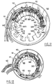
- FIGS. 1 to 4 show a synchronous motor 10 conforming to the invention, comprising a stator 100 and a rotor 200.
- the motor 10 is brushless, with rotor with flux concentration and stator wound on teeth, and operates with three-phase current.
- the stator 100 comprises a steel casing 110, having a lateral opening 111 for the passage in particular of the electrical supply conductors of the stator windings.
- the casing is provided externally with fixing lugs 112 and a lifting hook 113.
- the stator 100 comprises a magnetic circuit comprising, in the example shown, a plurality of identical sectors 120, one of which is shown in perspective in Figure 6.
- Each sector 120 is constituted by a bundle of identical magnetic sheets superimposed and clipped together so as to constitute a unitary assembly, the clipping being obtained according to a technique known in itself thanks to punctual deformations of each sheet in several points of hanging 121.
- the use of a pack of magnetic sheets makes it possible to limit losses by induced currents.
- the magnetic circuit of the stator could be formed by the superposition of sheets, each of generally annular shape, from which all the teeth 130 of the stator would be cut.
- the sectors could comprise several teeth each. Two sectors 120 form, when assembled, a tooth 130 of non-constant width, used for mounting an individual coil 340, as can be seen in FIG. 5 in particular.
- n teeth is in the example described equal to 12, the motor being intended to be supplied with three-phase current and the rotor comprising 8 poles.
- the number of poles of the rotor could be different and in particular be equal to 12 or 16 for example.
- Each sector 120 comprises, on its sides 123a and 123b intended to cooperate with the adjacent sectors 120, respective reliefs 124a and 124b.
- These reliefs 124a and 124b have complementary shapes, with a generally triangular profile in top view, one recessed the other projecting, with two substantially straight sides connected by a rounding. The cooperation of reliefs 124a and 124b contributes to the good positioning of sectors 120 together when assembling the magnetic circuit of the stator.
- Each sector 120 also has, on its sides 123a and 123b, grooves 125a and 125b respectively, each of semi-circular cross section, located in the in the vicinity of the reliefs 124a and 124b, and forming holes 125 of circular section when sectors 120 are assembled. These holes 125 are used for mounting three detectors 190, as will be explained below.
- the air gap E at the interface between two adjacent sectors 120, passes through the middle of the corresponding tooth 130, which allows reduce magnetic losses since the magnetic flux can circulate without meet the air gap of a half tooth to the adjacent half tooth of the same sector 120, during machine operation.
- the sectors can be made with elements cut practically without falling with relatively small tools, therefore capable of high rates.
- All of the sectors 120 are forcibly inserted into the cylindrical casing 110 and the cohesion of the magnetic circuit formed by all of the sectors 120 is ensured by the radial compression forces exerted by the casing 110 on the sectors 120, the support spans of the sectors between them being relatively large.
- Each sector 120 defines a notch 140 whose opposite sides 141a and 141b each make an angle i of more than 90 ° with the adjacent regions 142a and 142b of the bottom of the notch 140, themselves perpendicular to the rays passing through the line of connection of the tooth concerned with the bottom of the notch.
- the angle i is 90.4 °, this value being of course only an example.
- each tooth 130 does not include, in the vicinity of its free end 131, of polar expansions, unlike a large number of known stators which have semi-closed notches.
- the end parts 132a and 132b of each tooth 130, located between its free end 131 and the cutouts 144a or 144b are aligned with the sides 14aa and 141b, respectively.
- the free end 131 is a portion of cylinder of revolution, of the same axis as the axis of rotation of the rotor, and concave towards the rotor.
- each notch has a middle region 142c connecting the regions 142a and 142b and perpendicular to a radius intersecting the notch 140 at mid-width, shown in broken lines in Figure 7.
- each tooth 130 receives a coil individual 340, occupying in each notch 140 adjacent to the tooth 130 considered, substantially half the volume of this notch.
- FIG. 8 shows an individual coil 340 in isolation. is formed by winding around a geometric winding axis W of a bundle 341 of enamelled electrical wires 342, this bundle being substantially flat in cross section, as can be seen in Figure 9.
- the beam 341 comprises ten individual conductors 342, each of circular cross section. Beam 341 forms a twenty coiled 343 turns.
- the conductors 342 are electrically isolated each other at the level of the turns thanks to the use of enameled wire.
- the drivers 342 are stripped at their ends to form electrical connection ends 344a and 344b, each bent in the form of a hook towards a median plane of the coil, perpendicular to the winding axis W. These hooks, at the end of the manufacture of the coil, are open towards the body thereof.
- the inner section of the coil 340 has a general shape rectangular, as can be seen in Figure 10.
- the coils 340 are wound on shapes with two large opposite flat faces making the same between them angle as the sides 141a and 141b of a tooth, so that the width of the inner section of each coil varies substantially from one end face to the opposite face. We can notice this when trying to mount a coil upside down on a tooth 130 of the stator 100.
- the coils 340 are electrically connected by one end of electrical connection 344a or 344b to electrical conductors sheathed 150, partially stripped, before being mounted on the teeth 130 of the stator 100.
- the hooks formed by the ends 344a and 344b are for example arranged so to substantially match the outside diameter of the electrical conductors 150 in the bared parties 151.
- These bared parties may be formed not only for ends of electrical conductors 150 but still between them, by removal of the plastic insulating sheath over a limited length.
- strings of two coils 340 are formed which are then mounted on the corresponding teeth 130, as illustrated in FIG. 11.
- 349 sheets of insulation are interposed between the teeth and the bottom of the notches and the coils. The ends of these sheets 349 can be seen in Figures 5 and 11.
- shims of holding 160 are slid into the cutouts 144a, 144b to close the notches 140.
- These wedges 160 comprise, as can be seen in FIG. 4, partitions 161 extending between the parts of the two coils 340 housed in the notch 140 concerned.
- the cables 150 extend along substantially circular paths on one side of the magnetic circuit of the stator, in removal of the free ends 131 of the teeth, as shown in FIG. 12, these cables being attached to each other by necklaces, and the stator is impregnated with an insulating resin, in a conventional manner.
- the precise connection diagram electric of the twelve coils between them is given in figure 20, but it is only of an example.
- the convergence of the sides 141a and 141b of the tooth 130 towards the rotor and the corresponding shape of the inner section of the coil contribute to its immobilization on tooth 130. Repair can be done on site, without having to return the machine to the manufacturer, and without having to perform a new one impregnation of the stator, which shortens the repair time.
- the engine 10 can advantageously be delivered with one or more replacement coils 340.
- the rotor 200 This comprises a non-magnetic shaft 210, shown in isolation in front view on the FIG. 15, comprising a central part 211, of generally annular shape, and at its periphery a plurality of ribs 220 used for the attachment of pole pieces 230 each consisting of a bundle of superimposed identical magnetic sheets and clipped.
- the use of superimposed magnetic sheets reduces losses by induced currents.
- the ribs 220 have a general shape in cross section of T.
- the pole pieces 230 are not magnetically connected to each other, given the use of a non-magnetic material to make the tree.
- Each pole piece 230 has a cutout 250 having a shape adapted to engage on a rib 220, by sliding parallel to the axis of rotation of the rotor.
- the ribs 220 are made in one piece with the central part 211, in aluminum, by machining in the example considered, but other techniques such as wire drawing or injection could be used. Note that the pole pieces 230, in the example described, are not engaged on anything other than the ribs of the tree.
- the ribs 220 could be replaced by added bars, made integral with end cheeks, when the rotor is relatively short or not intended to rotate at high speed, as will be explained later.
- the cutout 250 is symmetrical with respect to a median plane passing through its middle and containing a radius. It has a bottom 251 which is intended to come into contact with the radially outer face 221 of the corresponding rib 220.
- the bottom 251 is connected to opposite sides 252, each having a first rounded part 252a, with a radius of curvature R a , an oblique rectilinear intermediate part 252b making a non-zero angle ii with the radius passing through the middle of the bottom 251 and a second rounded part 252c, of radius of curvature R c .
- R a is 3mm
- R c is 5mm
- the angle ii is 70 °.
- the cutout 250 has a narrowed opening, which allows attachment to a rib 220.
- each rib 220 is substantially complementary to that of the cutout 252, except for the presence of a chamfer 221a at the edge of the radially outer face 221 of the rib 220.
- Each side 222 of the rib thus comprises a part rounded 222a with the same radius of curvature R a as the rounded part 252a, a rectilinear part 222b parallel to the part 252b when the pole piece 230 is in place on the shaft 210 and a rounded part 222c with the same radius of curvature R c as part 252c.
- the radially inner edges 233 of the pole piece 230 located on either side of the notch 250, extend back from the regions 213 of the shaft 210 located between the ribs 220, as can be seen in the Figures 17 and 18 in particular.
- a free space 260 is thus created between two adjacent ribs 220, the pole pieces 230 engaged on these ribs and the shaft 210.
- Permanent magnets 270 of slightly trapezoidal section are arranged radially, being inserted between the pole pieces 230, as shown in the figure 18.
- Each magnet 270 has, when observed along the axis of rotation of the rotor, a slightly wedge-shaped, its width decreasing going radially outwards.
- Each magnet 270 which has transverse magnetization can be in one piece or be consisting of several magnetic elements placed end to end. The magnetic poles of same polarity of two adjacent magnets 270 are directed towards the pole piece 230 located between these magnets 270, as illustrated in FIG. 18.
- each magnet 270 consists of three magnetic elements 270a, 270b and 270c placed end to end tip in the direction of the X axis of rotation of the rotor, as can be seen in Figure 3.
- the magnets 270 extend over practically the entire radial dimension of the sides 238 of the pole pieces 230 and in contact with them.
- the angle between them of the opposite plane faces of the magnets 270 coming into contact with the pole pieces 230 is relatively small, a few degrees.
- the angle iii between the side 238 of a pole piece 230 and the adjacent edge 233 is equal in the example shown in Figure 16 at 92.4 °.
- the radially outer side 235 of a pole piece 230 is of circular cross section, with a radius of curvature less than the maximum radius of the rotor, so that each pole piece 230 has an outer face 235 which forms a slightly convex lobe towards the exterior, as can be seen in FIG. 18.
- the convex shape of the pole pieces 230 makes it possible to reduce the torque ripples and to create a flow of cooling air.
- the housings formed between the pole pieces 230, and in which are placed magnets 270, tend to widen under the effect of centrifugal force when the rotor 200 rotates at a speed greater than a predetermined speed, taking into account the elasticity of the materials used, this enlargement tending to decrease when the speed rotation decreases.
- the magnets 270 have a radial dimension chosen such that when they are placed in the corresponding housings of the rotor, their ends radially outside is set back from the radially outside edge, adjacent to the magnets, pole pieces.
- the magnets 270 are arranged to engage in the intervals formed by enlargement of the aforementioned housings when the rotor rotates at a speed greater than said predetermined speed, so that the pole pieces 230 enclose the magnets 270 when the speed of the rotor drops below said predetermined speed.
- the presence of spaces 260 facilitates the positioning of magnets 270. It is understood that there is thus a simple and effective means for securing the magnets 270 to pole pieces 230.
- the rotor 200 can be turned at a speed for example 10% higher than its nominal rotation speed, or even at a speed 20% higher than this.
- the magnets 270 are easily placed, since it is not necessary to insert them initially between the pole pieces 230 with a significant force, the final positioning of the magnets 270 taking place by itself when the rotor 200 is rotated. In addition, by rotating more or slower the rotor, one can if necessary obtain a more or less large displacement of the pole pieces 230 and magnets 270 and act slightly on the outside diameter of the rotor. This can make it possible to produce the magnets 270 and the pole pieces 230, as well as stator 100, with wider manufacturing tolerances, since it is possible adjust the outside diameter of rotor 200 to a desired value by rotating it more or less quickly.
- Magnets 270 have a low electrical resistivity, but are not not subjected to heating risking demagnetize them thanks to the protection conferred vis-à-vis the pulsating flow by the pole pieces 230, at high speeds.
- the wedge shape of the magnets 270 allows to exercise on the parts of the pieces polar 230 which encloses the ribs 220 of the compressive forces which tend to close the cutouts 250 on the ribs 220, especially since the speed is high, so that the assembly is self-locking.
- the aforementioned compression forces reduce the width of the parts of the pole pieces located on either side a rib, therefore to benefit from a greater width at the level of the connection of the rib to the shaft and use to make the latter a material less mechanically resistant than non-magnetic steel, but less expensive and more lightweight, such as aluminum.
- End cheeks 280 and 290 are fixed on the shaft 210 on either side of the latter, for axially locking the pole pieces 230 and the magnets 270. These cheeks define a stage of the machine.
- the rotor 200 may include several floors separated by intermediate cheeks and the number of magnets 270 by floor can be for example between 4 and 64, which can be equal to 8 as in the example shown for an 8-pole motor. When multiple floors are used and are separated by intermediate cheeks, the number of cheeks will preferably be equal to number of floors plus one.
- the cheeks 280, 290 can be made for example from aluminum or non-magnetic steel.
- the cheeks 280 and 290 are fixed to the shaft 210 by means of bolts 281.
- Threads 500 are made on the cheeks 280, 290, at their periphery, to allow the fixing of balancing screws.
- the cheek 280 has a radially outer edge 282 circular, set back from the radially outer edge 235 of the pole pieces 230 and of the radially outer edge of the magnets 270, which is located substantially at the ends 235a of the curved faces.
- An annular zone A is thus formed around the cheek 280, allowing the reading of the magnetic field of the magnets 270 of the rotor by means of detectors 190 that we can see in Figure 4.
- the detectors 190 can slightly cover the rotor 200, thanks to the recessed positioning of the cheek 280.
- the detectors 190 are, in the example of embodiment described, among the number of three, the motor being three-phase, and each comprise a Hall effect sensor arranged to detect the magnetic field above the peripheral region A of the rotor 200, around of the cheek 280. The magnetic field is read along an axis parallel to the axis of rotation of the rotor, the Hall effect sensor covering the peripheral region A.
- the detectors 190 are mounted, in the example illustrated, on three consecutive teeth 130 located in the vicinity of hearing 111.
- Each detector 190 is fixed by a screw 191 to a tooth 130 of the stator, this screw 191 being engaged in a hole 125.
- Each detector 190 extends along the radial axis Z u , Z v or Z w of the associated tooth and crosses the coil 340 engaged on this tooth.
- the coils 340 have for this purpose an internal section whose length is large enough to allow the passage of the detector 190.
- the space provided between a coil and the corresponding tooth for the passage of the detector can be of the order of 5 mm, for example, such a space making it possible to isolate the coil and the tooth where there is no insulation 349.
- the direct reading of the magnetic field of permanent magnets 270 is advantageous because it avoids having to bring elements to the rotor specific only for reading the angular position of the rotor.
- the rotor manufacturing is simplified and reliability enhanced.
- the mounting detectors 190 in the space between the coils 340 and the teeth 130 turns out particularly compact, while allowing easy access to detectors 190 in order to replace, if necessary.
- Each detector 190 is positioned inside a coil 340 of given phase (u, v and w). Each detector 190 makes it possible to detect which polarity of the rotor is located opposite the associated coil (and therefore of the phase concerned) at a given time. Each detector 190 delivers a low or high signal depending on the detected polarity. Each detector 190 includes an electronic circuit for shaping the signals delivered by the Hall effect sensor, in order to reduce the sensitivity to parasites. Depending on the position of the rotor, there are six possibilities of combining the different signals delivered by the detectors 190, and each change of triplet constituted by the states of the detectors 190 corresponding to a determined angular position of the rotor.
- Each detector 190 further includes a temperature sensor.
- the rotor 200 comprises, on at least one of the cheeks 280 and 290, fins 291 cooling, visible in Figure 1 in particular. Note that an action of additional cooling is obtained thanks to the presence of lobes 235 formed by the pole pieces 230 at the periphery of the rotor, which generate an air current cooling at the heart of the engine.
- the invention makes it possible for example to manufacture rotating machines electric from a range of magnetic circuits of stators and rotors prefabricated, of different diameters, the stators with standard teeth.
- Only the coils can, for example, be manufactured on measurement for a stator magnetic circuit made from prefabricated elements, in determining the number of turns of the coil, the diameter of the conductor wires of the bundle flat and the number of these wires, depending on the performance requested by the user of the machine.
- the invention is not limited to a synchronous motor and also applies to a generator.
- the rotor can be inside or outside.
- the electrical power of the machine can be for example between 1 and 750 kW.
- the speed of rotation of the rotor can be for example between 1000 and 10,000 rpm.
- a machine according to the invention can also find applications when the speed is less than 1000 rpm.
- the outside diameter of the machine can be for example between 50 mm and 1 m; in applications the more common, the outside diameter may be between 100 and 600 mm.
- the invention is not limited to a particular number of poles or to the supply of the stator with three-phase current.
- the current can be polyphase with n phase phases, n different from three.
- the tree can be made of other non-magnetic materials than aluminum, for example aluminum alloys.
- stator teeth could have one side facing the rotor other that cylindrical of revolution around the axis of the rotor.
- the notches could be semi-closed.
- the pole pieces 230 ′ are stacked on bars 220 ', held by end cheeks secured to the shaft, as illustrated in Figure 20.
- the magnets 270 ' which have a wedge shape, are arranged between the pole pieces 230 'engaged on the bars 220 '.
- the pole pieces may have a recess, as shown in the Figure 21, to retain the magnets 270 'before centrifugation.
Abstract
Description
- La figure 1 est une vue schématique en perspective d'un moteur synchrone conforme à un exemple de mise en oeuvre de l'invention,
- la figure 2 est une vue schématique de dessus selon la flèche II de la figure 1,
- la figure 3 est une coupe axiale schématique du moteur selon III-III de la figure 2,
- la figure 4 est une vue agrandie du détail IV de la figure 2,
- la figure 5 représente isolément, en perspective et d'une manière schématique, le stator,
- la figure 6 représente isolément, en perpective, un secteur du circuit magnétique du stator,
- la figure 7 illustre l'assemblage du secteur de la figure 6 avec un secteur identique,
- la figure 8 représente isolément, en perspective, une bobine individuelle,
- la figure 9 est une section selon IX-IX de la figure 8,
- la figure 10 représente de manière schématique un chapelet de bobines utilisé pour la fabrication du stator,
- la figure 11 illustre de manière schématique la mise en place des chapelets de bobines sur le stator, au cours de la fabrication du stator,
- la figure 12 est une vue analogue à la figure 11, très schématique et simplifiée, tous les chapelets ayant été mis en place, pour illustrer le trajet circulaire des câbles d'amenée du courant,
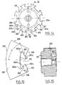
- la figure 13 est une vue schématique de face du rotor,
- la figure 14 représente isolément, en vue de face, l'arbre du rotor,
- la figure 15 est une section axiale schématique selon XV-XV de la figure 14,
- la figure 16 représente isolément, en vue de dessus, une pièce polaire du rotor,
- la figure 17 illustre l'assemblage des pièces polaires sur l'arbre du rotor,
- la figure 18 est une section transversale, schématique, de l'arbre du rotor après mise en place des aimants et des pièces polaires, et
- la figure 19 est un schéma non limitatif donnant un exemple de connexion électrique des bobines (numérotées de 1 à 12) entre elles,
- la figure 20 est une copie transversale schématique d'une variante de réalisation du rotor, et,
- la figure 21 représente un détail de la figure 20.
- sa structure particulièrement compacte permet de le monter en porte-à-faux à l'extrémité d'un arbre, donc de diminuer le nombre de roulements et les pertes mécaniques par friction, ainsi que les problèmes de lubrification,
- le rotor peut tourner à une vitesse de rotation élevée sans craindre un détachement des aimants ni un échauffement excessif de ces derniers, ceux-ci étant peu exposés aux courants induits de surface,
- les bobines individuelles peuvent être aisément mises en place et remplacées, sans avoir à procéder à une réimprégnation du stator,
- la masse des aimants peut être relativement faible, et il n'est pas nécessaire de la fractionner,
- le nombre de dents et de bobines est relativement faible, ce qui facilite la fabrication,
- les têtes de bobines sont très courtes, ce qui permet d'obtenir un faible encombrement axial,
- les phases peuvent être bien séparées électriquement, sans contacts ni croisements,
- les spires des bobines peuvent être bien jointives, ce qui permet un bon remplissage des encoches,
- les ondulations de couple peuvent être rendues négligeables.
Claims (35)
- Machine tournante électrique, comportant un rotor (200) à concentration de flux, comprenant des aimants permanents (270 ; 270') disposés entre des pièces polaires (230 ; 230') et un stator (100) bobiné sur dents.
- Machine selon la revendication 1, caractérisée par le fait que la forme des pièces polaires (230) et celle des aimants (270) sont choisies de manière à minimiser la différence Ld - Lq, où Ld est l'inductance dans l'axe direct et Lq est l'inductance dans l'axe en quadrature.
- Machine selon la revendication 1 ou 2, caractérisée par le fait que les dents (130) présentent une largeur non constante, augmentant en éloignement du rotor à partir d'une certaine distance de leur extrémité libre.
- Machine selon l'une quelconque des revendications 1 ou 3, caractérisée par le fait que les aimants (270) présentent une forme de coin lorsqu'observés selon l'axe de rotation du rotor, de largeur diminuant en éloignement de l'axe géométrique de rotation du rotor.
- Machine selon l'une quelconque des revendications 1 à 4, caractérisée par le fait que les pièces polaires (230) présentent des découpes (250) et sont engagées par ces découpes sur des nervures (220) de l'arbre (210).
- Machine selon la revendication précédente, caractérisée par le fait que lesdites nervures (220) sont réalisées d'un seul tenant avec une partie centrale (211) de l'arbre (210).
- Machine selon la revendication précédente, caractérisée par le fait que les nervures (220) et la partie centrale (211) de l'arbre (210) sont réalisées en un matériau amagnétique, notamment de l'aluminium.
- Machine selon l'une quelconque des revendications 5 à 7, caractérisée par le fait que des espaces (260) sont ménagés entre les bords radialement intérieurs des pièces polaires (230) et l'arbre (210).
- Machine selon l'une quelconque des revendications 5 à 8, caractérisée par le fait que chaque nervure (220) présente, en section transversale, un profil avec des côtés opposés (222) ayant des parties inclinées faisant un angle (ii) avec un rayon passant par le milieu de la nervure (222), cet angle étant choisi de manière à permettre l'emploi, pour réaliser les nervures, d'un matériau moins résistant aux contraintes de cisaillement que celui utilisé pour réaliser les pièces polaires (230).
- Machine selon la revendication précédente, caractérisée par le fait que l'angle (ii) est de l'ordre de 70°.
- Machine selon l'une des revendications 9 et 10, caractérisée par le fait que ledit profil comporte des parties arrondies (222a, 222c).
- Machine selon la revendication 11, caractérisée par le fait que les parties arrondies (222a, 222c) présentent des rayons de courbure (Ra, Rc) différents.
- Machine selon l'une quelconque des revendications précédentes, caractérisée par le fait que les pièces polaires (230) présentent chacune, sur leur côté tourné vers le stator, une face (235) bombée, convexe vers le stator.
- Machine selon l'une quelconque des revendications précédentes, caractérisée par le fait que le rotor comporte au moins une joue d'extrémité (280) en un matériau amagnétique, dont la périphérie s'étend en retrait des bords des aimants (270) qui sont adjacents au stator.
- Machine selon l'une quelconque des revendications précédentes, le stator comportant ndents dents, le rotor npaires paires de pôles et le courant étant à nphases phases, caractérisée par le fait que le nombre de dents ndents est choisi de manière à avoir la relation ndents = npaires * nphases.
- Machine selon l'une quelconque des revendications précédentes, caractérisée par le fait que le rotor est agencé pour tourner à une vitesse comprise entre 1000 et 10 000 trs/mn.
- Machine selon l'une quelconque des revendications précédentes, caractérisée par le fait que sa dimension radiale extérieure est comprise entre 50 mm et 1 m.
- Machine selon l'une quelconque des revendications précédentes, caractérisée par le fait que le stator (100) comporte des bobines individuelles (340).
- Machine selon l'une quelconque des revendications précédentes, caractérisée par le fait que le stator comporte au moins une bobine individuelle (340) comportant un faisceau (341) de fils isolés (342), sensiblement plat, enroulé autour d'un axe géométrique d'enroulement (W) de manière à former une pluralité de spires superposées, la section transversale du faisceau, au niveau des spires superposées, ayant une grande dimension orientée sensiblement perpendiculairement à l'axe d'enroulement (W) de la bobine.
- Machine selon la revendication précédente, caractérisée par le fait que les fils (342) sont de section circulaire, de diamètre compris entre 0,3 mm et 2,5 mm.
- Machine selon la revendication 19 ou 20, caractérisée par le fait que la section intérieure de la bobine (340) est sensiblement rectangulaire.
- Machine selon l'une quelconque des revendications 19 à 21, caractérisée par le fait que la section intérieure de la bobine (340) est plus large d'un côté que de l'autre, de façon à permettre son montage sur une dent (130) présentant un profil complémentaire avec un certain effet de serrage.
- Machine selon l'une des revendications 19 à 22, caractérisée par le fait que les fils (342) sont dénudés aux extrémités de connexion électrique de la bobine (340) et recourbés pour former des crochets.
- Machine selon la revendication 23, caractérisée par le fait que lesdits crochets sont dirigés vers un plan médian de la bobine, perpendiculaire à l'axe d'enroulement (W).
- Machine selon l'une quelconque des revendications 19 à 24, caractérisée par le fait que la bobine (340) présente une section intérieure dont la dimension du grand côté est supérieure à la dimension axiale de la dent sur laquelle est engagée la bobine, afin de ménager un espace suffisant pour permettre le passage d'un détecteur (190) permettant de délivrer un signal représentatif de la rotation du rotor.
- Machine selon l'une quelconque des revendications précédentes, caractérisée par le fait qu'elle comporte au moins un détecteur (190) comportant un capteur de champ magnétique, monté sur le stator de manière à détecter le champ magnétique des aimants (270) du rotor depuis un emplacement venant en recouvrement, lorsque la machine est observée selon l'axe de rotation du rotor, d'une région périphérique (A) du rotor.
- Machine selon la revendication précédente, le courant étant à n phases, caractérisée par le fait qu'elle comporte n détecteurs (190) montés sur des dents consécutives à proximité d'une ouie (111) d'un carter (110) de la machine.
- Machine selon l'une des deux revendications immédiatement précédentes, caractérisée par le fait que le ou les détecteurs (190) sont fixés sur le circuit magnétique du stator et s'étendent chacun selon l'axe radial (Zu ; Zv ; Zw) d'une dent.
- Machine selon l'une quelconque des revendications 26 à 28, caractérisée par le fait que le ou les détecteurs (190) comportent également, outre un capteur de champ magnétique, un capteur de température.
- Machine selon l'une quelconque des revendications précédentes, caractérisée par le fait que le rotor comporte au moins une joue (280) en un matériau amagnétique, le bord radialement extérieur de cette joue s'étendant au retrait du bord radialement extérieur des aimants et des pièces polaires, de manière à ménager une région annulaire (A) dans laquelle le champ magnétique du ou des aimants (270) peut être lu par un ou plusieurs détecteurs.
- Machine selon l'une quelconque des revendications précédentes, caractérisée par le fait qu'elle comporte des bobines individuelles (340) comprenant des extrémités de connexion formées par un faisceau plat (341) de fils dénudés recourbés en forme de crochet, ces extrémités de connexion (344a ; 344b) étant soudées sur des portions localement dénudées (151) de câbles électriques gainés (150).
- Machine selon l'une quelconque des revendications précédentes, caractérisée par le fait que le circuit magnétique du stator comporte des secteurs (120) assemblés, définissant des entrefers (E) coupant les dents (130) à mi-largeur.
- Machine selon la revendication précédente, caractérisée par le fait que les secteurs présentent des reliefs coopérant (124a, 124b) sur leurs côtés d'accostage (123a, 123b).
- Machine selon l'une quelconque des revendications précédentes, caractérisée par le fait que le circuit magnétique du stator est inséré à force dans un carter cylindrique (110).
- Machine selon l'une quelconque des revendications précédentes, caractérisée par le fait qu'elle constitue un moteur synchrone.
Priority Applications (15)
| Application Number | Priority Date | Filing Date | Title |
|---|---|---|---|
| EP02291384A EP1249919B1 (fr) | 2000-05-03 | 2001-04-17 | Rotor de machine electrique tournante |
| US09/843,808 US6891299B2 (en) | 2000-05-03 | 2001-04-30 | Rotary electric machine having a flux-concentrating rotor and a stator with windings on teeth |
| JP2001135282A JP2002010600A (ja) | 2000-05-03 | 2001-05-02 | ロータリ式電動機器 |
| FR0108933A FR2823617B1 (fr) | 2001-04-17 | 2001-07-05 | Machine electrique a rotor exterieur |
| FR0109180A FR2823615A1 (fr) | 2001-04-17 | 2001-07-10 | Stator de machine electrique |
| US10/121,674 US20020149281A1 (en) | 2001-04-17 | 2002-04-15 | Stator for an electric machine |
| US10/121,577 US20020171305A1 (en) | 2001-04-17 | 2002-04-15 | Electric machine having an outer rotor |
| ES02290954T ES2233780T3 (es) | 2001-04-17 | 2002-04-16 | Maquina electrica con rotor exterior. |
| DE60201937T DE60201937T2 (de) | 2001-04-17 | 2002-04-16 | Elektrische Maschine mit äusserem Läufer |
| EP02290954A EP1251023B1 (fr) | 2001-04-17 | 2002-04-16 | Machine électrique à rotor extérieur |
| EP02290955A EP1251625A1 (fr) | 2001-04-17 | 2002-04-16 | Stator de machine électrique |
| AT02290954T ATE282533T1 (de) | 2001-04-17 | 2002-04-16 | Elektrische maschine mit äusserem läufer |
| JP2002115014A JP2002325384A (ja) | 2001-04-17 | 2002-04-17 | 電機用固定子 |
| JP2002115038A JP4195788B2 (ja) | 2001-04-17 | 2002-04-17 | 外部回転子を備えた同期回転電機 |
| JP2006262849A JP2007049898A (ja) | 2000-05-03 | 2006-09-27 | ロータリ式電動機器 |
Applications Claiming Priority (4)
| Application Number | Priority Date | Filing Date | Title |
|---|---|---|---|
| FR0005639A FR2808627B1 (fr) | 2000-05-03 | 2000-05-03 | Rotor de machine tournante electrique et procede de fabrication |
| FR0005639 | 2000-05-03 | ||
| FR0102263A FR2821023A1 (fr) | 2001-02-20 | 2001-02-20 | Roue motrice a moteur synchrone |
| FR0102263 | 2001-04-20 |
Related Child Applications (2)
| Application Number | Title | Priority Date | Filing Date |
|---|---|---|---|
| EP02291384A Division EP1249919B1 (fr) | 2000-05-03 | 2001-04-17 | Rotor de machine electrique tournante |
| EP02291384.2 Division-Into | 2002-06-05 |
Publications (3)
| Publication Number | Publication Date |
|---|---|
| EP1152516A2 true EP1152516A2 (fr) | 2001-11-07 |
| EP1152516A3 EP1152516A3 (fr) | 2001-12-05 |
| EP1152516B1 EP1152516B1 (fr) | 2002-11-13 |
Family
ID=26212373
Family Applications (2)
| Application Number | Title | Priority Date | Filing Date |
|---|---|---|---|
| EP02291384A Expired - Lifetime EP1249919B1 (fr) | 2000-05-03 | 2001-04-17 | Rotor de machine electrique tournante |
| EP01400981A Expired - Lifetime EP1152516B1 (fr) | 2000-05-03 | 2001-04-17 | Machine tournante électrique à rotor à concentration de flux et à stator bobiné sur dents |
Family Applications Before (1)
| Application Number | Title | Priority Date | Filing Date |
|---|---|---|---|
| EP02291384A Expired - Lifetime EP1249919B1 (fr) | 2000-05-03 | 2001-04-17 | Rotor de machine electrique tournante |
Country Status (4)
| Country | Link |
|---|---|
| EP (2) | EP1249919B1 (fr) |
| AT (2) | ATE227898T1 (fr) |
| DE (3) | DE60118044T2 (fr) |
| ES (2) | ES2186664T3 (fr) |
Cited By (8)
| Publication number | Priority date | Publication date | Assignee | Title |
|---|---|---|---|---|
| EP1322026A1 (fr) * | 2001-12-22 | 2003-06-25 | Grundfos a/s | Stator d'un moteur électrique |
| WO2003073583A1 (fr) * | 2002-02-28 | 2003-09-04 | Abb Research Ltd. | Generateur synchrone |
| FR2932618A1 (fr) * | 2008-06-16 | 2009-12-18 | Leroy Somer Moteurs | Rotor a aimants permanents et machine tournante comportant un tel rotor |
| US7911103B2 (en) | 2006-01-03 | 2011-03-22 | Moteurs Leroy-Somer | Rotary electrical machine including pole pieces and permanent magnets |
| WO2012164519A1 (fr) | 2011-05-31 | 2012-12-06 | Moteurs Leroy-Somer | Rotor a aimants permanents et machine tournante comportant un tel rotor |
| WO2013072890A2 (fr) | 2011-11-18 | 2013-05-23 | Moteurs Leroy-Somer | Rotor de machine éléctrique tournante a concentration de flux |
| WO2013072892A2 (fr) | 2011-11-18 | 2013-05-23 | Moteurs Leroy-Somer | Rotor de machine éléctrique tournante a aimants permanents |
| CN105121250A (zh) * | 2013-04-15 | 2015-12-02 | 西门子公司 | 具有在部分圆周上的壳体的电机 |
Families Citing this family (12)
| Publication number | Priority date | Publication date | Assignee | Title |
|---|---|---|---|---|
| US6700288B2 (en) * | 2001-08-15 | 2004-03-02 | Drs Power & Control Technologies, Inc. | High speed rotor |
| FR2852162B1 (fr) | 2003-03-06 | 2005-09-23 | Leroy Somer Moteurs | Machine electrique tournante comportant un stator et deux rotors |
| KR101225971B1 (ko) * | 2006-04-07 | 2013-01-24 | 엘지전자 주식회사 | 모터 및 그를 갖는 공기조화기 |
| WO2007117078A2 (fr) * | 2006-04-07 | 2007-10-18 | Lg Electronics Inc. | Dispositif de climatisation et moteur pour dispositif de climatisation |
| FR2903824A1 (fr) * | 2006-07-13 | 2008-01-18 | Leroy Somer Moteurs | Rotor de machine tournante electrique et procede de fabrication |
| EP2066008B1 (fr) * | 2007-11-29 | 2011-08-03 | Siemens Aktiengesellschaft | Stator d'une machine dynamométrique doté de moyens d'enregistrement de la température |
| CN101608393B (zh) * | 2009-07-20 | 2013-03-27 | 江门金羚电机有限公司 | 一种家用离心式脱水机 |
| JP5241769B2 (ja) | 2010-05-12 | 2013-07-17 | 三菱電機株式会社 | 電動式パワーステアリング装置用モータ |
| KR101949198B1 (ko) * | 2011-09-08 | 2019-02-20 | 삼성전자주식회사 | 모터와 이를 가지는 세탁기 |
| CN202334208U (zh) * | 2011-11-16 | 2012-07-11 | 宁波威士顿车业有限公司 | 自行车用轮毂发电机 |
| FR3105633B1 (fr) | 2019-12-20 | 2022-06-24 | Nidec Psa Emotors | Rotor de machine electrique tournante |
| DE102021117625A1 (de) | 2021-07-08 | 2023-01-12 | Knorr-Bremse Systeme für Nutzfahrzeuge GmbH | Permanenterregte Elektromaschine |
Citations (8)
| Publication number | Priority date | Publication date | Assignee | Title |
|---|---|---|---|---|
| EP0365689A1 (fr) * | 1988-04-30 | 1990-05-02 | Fanuc Ltd. | Moteur synchrone |
| EP0438594A1 (fr) * | 1989-06-26 | 1991-07-31 | Fanuc Ltd. | Structure de rotor du type radial |
| US5091668A (en) * | 1989-12-08 | 1992-02-25 | Gec Alsthom Sa | Motor having flux-concentrating permanent magnets |
| US5162686A (en) * | 1989-11-27 | 1992-11-10 | Gec Alsthom Sa | Motor rotor having magnets |
| EP0866540A2 (fr) * | 1997-03-18 | 1998-09-23 | Electric Boat Corporation | Rotor pour moteur ou générateur |
| EP0872943A1 (fr) * | 1997-04-16 | 1998-10-21 | Japan Servo Co. Ltd. | Machine tornante électrodynamique à aimants permanents ayant un stator a bobinage concentré |
| US5841212A (en) * | 1996-04-15 | 1998-11-24 | Hitachi Metals, Ltd. | Permanent magnet field type rotating machine |
| FR2784815A1 (fr) * | 1998-10-20 | 2000-04-21 | Valeo Equip Electr Moteur | Machine electrique tournante, en particulier alternateur de vehicule automobile, possedant des moyens perfectionnes de reduction de bruit |
Family Cites Families (2)
| Publication number | Priority date | Publication date | Assignee | Title |
|---|---|---|---|---|
| US4339874A (en) * | 1978-12-26 | 1982-07-20 | The Garrett Corporation | Method of making a wedge-shaped permanent magnet rotor assembly |
| EP1001507B1 (fr) * | 1998-11-13 | 2006-03-01 | Conception et Développement Michelin | Machine électrique dont le rotor est spécialement adapté aux hautes vitesses |
-
2001
- 2001-04-17 ES ES01400981T patent/ES2186664T3/es not_active Expired - Lifetime
- 2001-04-17 EP EP02291384A patent/EP1249919B1/fr not_active Expired - Lifetime
- 2001-04-17 DE DE60118044T patent/DE60118044T2/de not_active Expired - Lifetime
- 2001-04-17 AT AT01400981T patent/ATE227898T1/de not_active IP Right Cessation
- 2001-04-17 EP EP01400981A patent/EP1152516B1/fr not_active Expired - Lifetime
- 2001-04-17 AT AT02291384T patent/ATE320674T1/de not_active IP Right Cessation
- 2001-04-17 ES ES02291384T patent/ES2258603T3/es not_active Expired - Lifetime
- 2001-04-17 DE DE20107523U patent/DE20107523U1/de not_active Expired - Lifetime
- 2001-04-17 DE DE60100046T patent/DE60100046T2/de not_active Expired - Lifetime
Patent Citations (8)
| Publication number | Priority date | Publication date | Assignee | Title |
|---|---|---|---|---|
| EP0365689A1 (fr) * | 1988-04-30 | 1990-05-02 | Fanuc Ltd. | Moteur synchrone |
| EP0438594A1 (fr) * | 1989-06-26 | 1991-07-31 | Fanuc Ltd. | Structure de rotor du type radial |
| US5162686A (en) * | 1989-11-27 | 1992-11-10 | Gec Alsthom Sa | Motor rotor having magnets |
| US5091668A (en) * | 1989-12-08 | 1992-02-25 | Gec Alsthom Sa | Motor having flux-concentrating permanent magnets |
| US5841212A (en) * | 1996-04-15 | 1998-11-24 | Hitachi Metals, Ltd. | Permanent magnet field type rotating machine |
| EP0866540A2 (fr) * | 1997-03-18 | 1998-09-23 | Electric Boat Corporation | Rotor pour moteur ou générateur |
| EP0872943A1 (fr) * | 1997-04-16 | 1998-10-21 | Japan Servo Co. Ltd. | Machine tornante électrodynamique à aimants permanents ayant un stator a bobinage concentré |
| FR2784815A1 (fr) * | 1998-10-20 | 2000-04-21 | Valeo Equip Electr Moteur | Machine electrique tournante, en particulier alternateur de vehicule automobile, possedant des moyens perfectionnes de reduction de bruit |
Non-Patent Citations (2)
| Title |
|---|
| PATENT ABSTRACTS OF JAPAN vol. 2000, no. 08, 6 octobre 2000 (2000-10-06) & JP 2000 152537 A (CONCEPTION &DEV MICHELIN SA), 30 mai 2000 (2000-05-30) * |
| WEINMANN D: "APPLICATIONS OF NDFEB-MAGNETS IN MOTORS" REVUE GENERALE DE L'ELECTRICITE,FR,RGE. PARIS, no. 4, 1 avril 1991 (1991-04-01), pages 45-51, XP000227187 ISSN: 0035-3116 * |
Cited By (12)
| Publication number | Priority date | Publication date | Assignee | Title |
|---|---|---|---|---|
| EP1322026A1 (fr) * | 2001-12-22 | 2003-06-25 | Grundfos a/s | Stator d'un moteur électrique |
| WO2003073583A1 (fr) * | 2002-02-28 | 2003-09-04 | Abb Research Ltd. | Generateur synchrone |
| US7911103B2 (en) | 2006-01-03 | 2011-03-22 | Moteurs Leroy-Somer | Rotary electrical machine including pole pieces and permanent magnets |
| FR2932618A1 (fr) * | 2008-06-16 | 2009-12-18 | Leroy Somer Moteurs | Rotor a aimants permanents et machine tournante comportant un tel rotor |
| WO2009153511A2 (fr) * | 2008-06-16 | 2009-12-23 | Moteurs Leroy-Somer | Rotor a aimants permanents et machine tournante comportante un tel rotor |
| WO2009153511A3 (fr) * | 2008-06-16 | 2010-05-14 | Moteurs Leroy-Somer | Rotor a aimants permanents et machine tournante comportante un tel rotor |
| WO2012164519A1 (fr) | 2011-05-31 | 2012-12-06 | Moteurs Leroy-Somer | Rotor a aimants permanents et machine tournante comportant un tel rotor |
| WO2013072890A2 (fr) | 2011-11-18 | 2013-05-23 | Moteurs Leroy-Somer | Rotor de machine éléctrique tournante a concentration de flux |
| WO2013072892A2 (fr) | 2011-11-18 | 2013-05-23 | Moteurs Leroy-Somer | Rotor de machine éléctrique tournante a aimants permanents |
| CN105121250A (zh) * | 2013-04-15 | 2015-12-02 | 西门子公司 | 具有在部分圆周上的壳体的电机 |
| CN105121250B (zh) * | 2013-04-15 | 2017-07-25 | 西门子公司 | 具有在部分圆周上的壳体的电机 |
| US9866086B2 (en) | 2013-04-15 | 2018-01-09 | Siemens Aktiengesellschaft | Electrical machine having a housing over a partial circumference |
Also Published As
| Publication number | Publication date |
|---|---|
| DE60100046T2 (de) | 2003-08-21 |
| DE20107523U1 (de) | 2001-07-12 |
| DE60118044T2 (de) | 2006-11-16 |
| EP1152516B1 (fr) | 2002-11-13 |
| DE60100046D1 (de) | 2002-12-19 |
| DE60118044D1 (de) | 2006-05-11 |
| EP1249919A1 (fr) | 2002-10-16 |
| ES2186664T3 (es) | 2003-05-16 |
| EP1152516A3 (fr) | 2001-12-05 |
| EP1249919B1 (fr) | 2006-03-15 |
| ES2258603T3 (es) | 2006-09-01 |
| ATE227898T1 (de) | 2002-11-15 |
| ATE320674T1 (de) | 2006-04-15 |
Similar Documents
| Publication | Publication Date | Title |
|---|---|---|
| EP1251629B1 (fr) | Machine électrique comportant au moins un détecteur de champ magnétique | |
| EP1152516B1 (fr) | Machine tournante électrique à rotor à concentration de flux et à stator bobiné sur dents | |
| EP1251623A1 (fr) | Stator de machine tournante électrique comportant des bobines individuelles démontables | |
| EP1251620B1 (fr) | Machine tournante électrique comportant un stator formé de secteurs assemblés | |
| FR2852461A1 (fr) | Stator pour machine dynamo-electriques | |
| EP1599930A2 (fr) | Machine electrique tournante comportant un stator et deux rotors | |
| EP1251622B1 (fr) | Bobine pour machine électrique tournante | |
| WO2015015089A2 (fr) | Rotor à griffes comportant un clip de fixation d'un fil d'extremite du bobinage et machine electrique associee | |
| FR3054746A1 (fr) | Machine electrique tournante munie d'un interconnecteur dote de bequilles d'appui | |
| WO2014174200A2 (fr) | Élément isolant muni de crochets de maintien de fils de bobinage d'un stator de machine électrique et stator correspondant | |
| EP2860847B1 (fr) | Stator bobiné à remplissage d'encoches optimisé et machine électrique correspondante | |
| FR3066333A1 (fr) | Rotor a poles vrilles pour machine electrique tournante synchrone. | |
| EP3259830B1 (fr) | Rotor de machine électrique tournante a aimants permanents segmentes | |
| FR3053543A1 (fr) | Machine electrique tournante munie d'un interconnecteur fixe sur le corps du stator | |
| FR3054748B1 (fr) | Machine electrique tournante munie d'un interconnecteur a traces de couplage empilees radialement | |
| EP3895294A1 (fr) | Rotor à arbre non traversant et machine électrique tournante associée | |
| WO2018020168A1 (fr) | Machine électrique tournante munie d'un interconnecteur à traces de couplage empilées radialement | |
| FR2802724A1 (fr) | Stator a dents convexes | |
| FR3033959A1 (fr) | Rotor de machine electrique tournante a configuration d'aimants permanents optimisee | |
| EP4338257A1 (fr) | Corps de stator pour machine électrique à flux axial | |
| FR3079685A1 (fr) | Stator de machine electrique tournante muni d'un bobinage a epingles ameliore. | |
| WO2018020167A1 (fr) | Machine électrique tournante munie d'un bobinage à configuration améliorée | |
| WO2019025150A1 (fr) | Rotor de machine électrique tournante muni d'un système de fixation de flasque amelioré | |
| FR2808627A1 (fr) | Rotor de machine tournante electrique et procede de fabrication | |
| FR3083651A1 (fr) | Stator bobine pour une machine electrique tournante |
Legal Events
| Date | Code | Title | Description |
|---|---|---|---|
| PUAI | Public reference made under article 153(3) epc to a published international application that has entered the european phase |
Free format text: ORIGINAL CODE: 0009012 |
|
| PUAL | Search report despatched |
Free format text: ORIGINAL CODE: 0009013 |
|
| AK | Designated contracting states |
Kind code of ref document: A2 Designated state(s): AT BE CH CY DE DK ES FI FR GB GR IE IT LI LU MC NL PT SE TR |
|
| AX | Request for extension of the european patent |
Free format text: AL;LT;LV;MK;RO;SI |
|
| 17P | Request for examination filed |
Effective date: 20011005 |
|
| AK | Designated contracting states |
Kind code of ref document: A3 Designated state(s): AT BE CH CY DE DK ES FI FR GB GR IE IT LI LU MC NL PT SE TR |
|
| AX | Request for extension of the european patent |
Free format text: AL;LT;LV;MK;RO;SI |
|
| GRAG | Despatch of communication of intention to grant |
Free format text: ORIGINAL CODE: EPIDOS AGRA |
|
| 17Q | First examination report despatched |
Effective date: 20020506 |
|
| GRAG | Despatch of communication of intention to grant |
Free format text: ORIGINAL CODE: EPIDOS AGRA |
|
| GRAH | Despatch of communication of intention to grant a patent |
Free format text: ORIGINAL CODE: EPIDOS IGRA |
|
| GRAG | Despatch of communication of intention to grant |
Free format text: ORIGINAL CODE: EPIDOS AGRA |
|
| GRAH | Despatch of communication of intention to grant a patent |
Free format text: ORIGINAL CODE: EPIDOS IGRA |
|
| AKX | Designation fees paid |
Free format text: AT BE CH CY DE DK ES FI FR GB GR IE IT LI LU MC NL PT SE TR |
|
| GRAA | (expected) grant |
Free format text: ORIGINAL CODE: 0009210 |
|
| AK | Designated contracting states |
Kind code of ref document: B1 Designated state(s): AT BE CH CY DE DK ES FI FR GB GR IE IT LI LU MC NL PT SE TR |
|
| PG25 | Lapsed in a contracting state [announced via postgrant information from national office to epo] |
Ref country code: TR Free format text: LAPSE BECAUSE OF FAILURE TO SUBMIT A TRANSLATION OF THE DESCRIPTION OR TO PAY THE FEE WITHIN THE PRESCRIBED TIME-LIMIT Effective date: 20021113 Ref country code: NL Free format text: LAPSE BECAUSE OF FAILURE TO SUBMIT A TRANSLATION OF THE DESCRIPTION OR TO PAY THE FEE WITHIN THE PRESCRIBED TIME-LIMIT Effective date: 20021113 Ref country code: AT Free format text: LAPSE BECAUSE OF FAILURE TO SUBMIT A TRANSLATION OF THE DESCRIPTION OR TO PAY THE FEE WITHIN THE PRESCRIBED TIME-LIMIT Effective date: 20021113 Ref country code: IE Free format text: LAPSE BECAUSE OF FAILURE TO SUBMIT A TRANSLATION OF THE DESCRIPTION OR TO PAY THE FEE WITHIN THE PRESCRIBED TIME-LIMIT Effective date: 20021113 Ref country code: GR Free format text: LAPSE BECAUSE OF FAILURE TO SUBMIT A TRANSLATION OF THE DESCRIPTION OR TO PAY THE FEE WITHIN THE PRESCRIBED TIME-LIMIT Effective date: 20021113 |
|
| REF | Corresponds to: |
Ref document number: 227898 Country of ref document: AT Date of ref document: 20021115 Kind code of ref document: T |
|
| REG | Reference to a national code |
Ref country code: GB Ref legal event code: FG4D Free format text: NOT ENGLISH |
|
| RIN1 | Information on inventor provided before grant (corrected) |
Inventor name: EYDELIE, ANDRE Inventor name: GAUTHIER, PASCAL Inventor name: GILLES, CHRISTOPHE Inventor name: SAINT-MICHEL, JACQUES Inventor name: COUPART, ERIC Inventor name: JADEAU, LAURENT Inventor name: AUGIER, PHILIPPE Inventor name: GUILLOT, JEAN-MARIE |
|
| REG | Reference to a national code |
Ref country code: CH Ref legal event code: EP |
|
| REG | Reference to a national code |
Ref country code: IE Ref legal event code: FG4D Free format text: FRENCH |
|
| REF | Corresponds to: |
Ref document number: 60100046 Country of ref document: DE Date of ref document: 20021219 |
|
| PG25 | Lapsed in a contracting state [announced via postgrant information from national office to epo] |
Ref country code: PT Free format text: LAPSE BECAUSE OF FAILURE TO SUBMIT A TRANSLATION OF THE DESCRIPTION OR TO PAY THE FEE WITHIN THE PRESCRIBED TIME-LIMIT Effective date: 20030213 Ref country code: DK Free format text: LAPSE BECAUSE OF FAILURE TO SUBMIT A TRANSLATION OF THE DESCRIPTION OR TO PAY THE FEE WITHIN THE PRESCRIBED TIME-LIMIT Effective date: 20030213 |
|
| GBT | Gb: translation of ep patent filed (gb section 77(6)(a)/1977) |
Effective date: 20030213 |
|
| NLV1 | Nl: lapsed or annulled due to failure to fulfill the requirements of art. 29p and 29m of the patents act | ||
| PG25 | Lapsed in a contracting state [announced via postgrant information from national office to epo] |
Ref country code: CY Free format text: LAPSE BECAUSE OF FAILURE TO SUBMIT A TRANSLATION OF THE DESCRIPTION OR TO PAY THE FEE WITHIN THE PRESCRIBED TIME-LIMIT Effective date: 20030417 Ref country code: LU Free format text: LAPSE BECAUSE OF NON-PAYMENT OF DUE FEES Effective date: 20030417 |
|
| PG25 | Lapsed in a contracting state [announced via postgrant information from national office to epo] |
Ref country code: MC Free format text: LAPSE BECAUSE OF NON-PAYMENT OF DUE FEES Effective date: 20030430 Ref country code: BE Free format text: LAPSE BECAUSE OF NON-PAYMENT OF DUE FEES Effective date: 20030430 |
|
| REG | Reference to a national code |
Ref country code: ES Ref legal event code: FG2A Ref document number: 2186664 Country of ref document: ES Kind code of ref document: T3 |
|
| REG | Reference to a national code |
Ref country code: IE Ref legal event code: FD4D Ref document number: 1152516E Country of ref document: IE |
|
| PLBE | No opposition filed within time limit |
Free format text: ORIGINAL CODE: 0009261 |
|
| STAA | Information on the status of an ep patent application or granted ep patent |
Free format text: STATUS: NO OPPOSITION FILED WITHIN TIME LIMIT |
|
| BERE | Be: lapsed |
Owner name: *MOTEURS LEROY-SOMER Effective date: 20030430 |
|
| 26N | No opposition filed |
Effective date: 20030814 |
|
| PG25 | Lapsed in a contracting state [announced via postgrant information from national office to epo] |
Ref country code: LI Free format text: LAPSE BECAUSE OF NON-PAYMENT OF DUE FEES Effective date: 20050430 Ref country code: CH Free format text: LAPSE BECAUSE OF NON-PAYMENT OF DUE FEES Effective date: 20050430 |
|
| REG | Reference to a national code |
Ref country code: CH Ref legal event code: PL |
|
| PGFP | Annual fee paid to national office [announced via postgrant information from national office to epo] |
Ref country code: DE Payment date: 20120626 Year of fee payment: 12 |
|
| PGFP | Annual fee paid to national office [announced via postgrant information from national office to epo] |
Ref country code: FR Payment date: 20120529 Year of fee payment: 12 Ref country code: GB Payment date: 20120420 Year of fee payment: 12 Ref country code: FI Payment date: 20120418 Year of fee payment: 12 Ref country code: SE Payment date: 20120425 Year of fee payment: 12 |
|
| PGFP | Annual fee paid to national office [announced via postgrant information from national office to epo] |
Ref country code: IT Payment date: 20120426 Year of fee payment: 12 |
|
| PGFP | Annual fee paid to national office [announced via postgrant information from national office to epo] |
Ref country code: ES Payment date: 20120416 Year of fee payment: 12 |
|
| REG | Reference to a national code |
Ref country code: SE Ref legal event code: EUG |
|
| GBPC | Gb: european patent ceased through non-payment of renewal fee |
Effective date: 20130417 |
|
| PG25 | Lapsed in a contracting state [announced via postgrant information from national office to epo] |
Ref country code: DE Free format text: LAPSE BECAUSE OF NON-PAYMENT OF DUE FEES Effective date: 20131101 Ref country code: GB Free format text: LAPSE BECAUSE OF NON-PAYMENT OF DUE FEES Effective date: 20130417 Ref country code: SE Free format text: LAPSE BECAUSE OF NON-PAYMENT OF DUE FEES Effective date: 20130418 |
|
| REG | Reference to a national code |
Ref country code: FR Ref legal event code: ST Effective date: 20131231 |
|
| REG | Reference to a national code |
Ref country code: DE Ref legal event code: R119 Ref document number: 60100046 Country of ref document: DE Effective date: 20131101 |
|
| PG25 | Lapsed in a contracting state [announced via postgrant information from national office to epo] |
Ref country code: FI Free format text: LAPSE BECAUSE OF NON-PAYMENT OF DUE FEES Effective date: 20130417 Ref country code: FR Free format text: LAPSE BECAUSE OF NON-PAYMENT OF DUE FEES Effective date: 20130430 Ref country code: IT Free format text: LAPSE BECAUSE OF NON-PAYMENT OF DUE FEES Effective date: 20130417 |
|
| REG | Reference to a national code |
Ref country code: ES Ref legal event code: FD2A Effective date: 20140609 |
|
| PG25 | Lapsed in a contracting state [announced via postgrant information from national office to epo] |
Ref country code: ES Free format text: LAPSE BECAUSE OF NON-PAYMENT OF DUE FEES Effective date: 20130418 |