EP1249609B1 - Pumpe mit selbstzentrierender, einsteckbarer Antriebswelle - Google Patents
Pumpe mit selbstzentrierender, einsteckbarer Antriebswelle Download PDFInfo
- Publication number
- EP1249609B1 EP1249609B1 EP20020006304 EP02006304A EP1249609B1 EP 1249609 B1 EP1249609 B1 EP 1249609B1 EP 20020006304 EP20020006304 EP 20020006304 EP 02006304 A EP02006304 A EP 02006304A EP 1249609 B1 EP1249609 B1 EP 1249609B1
- Authority
- EP
- European Patent Office
- Prior art keywords
- shaft
- pump
- ring
- self
- housing
- Prior art date
- Legal status (The legal status is an assumption and is not a legal conclusion. Google has not performed a legal analysis and makes no representation as to the accuracy of the status listed.)
- Expired - Lifetime
Links
- 238000007789 sealing Methods 0.000 claims description 17
- 229920001343 polytetrafluoroethylene Polymers 0.000 claims description 6
- 239000004810 polytetrafluoroethylene Substances 0.000 claims description 6
- 239000004809 Teflon Substances 0.000 claims description 4
- 229920006362 Teflon® Polymers 0.000 claims description 4
- 230000000284 resting effect Effects 0.000 claims 1
- 230000000694 effects Effects 0.000 description 4
- 239000000446 fuel Substances 0.000 description 3
- VYZAMTAEIAYCRO-UHFFFAOYSA-N Chromium Chemical compound [Cr] VYZAMTAEIAYCRO-UHFFFAOYSA-N 0.000 description 2
- 238000007747 plating Methods 0.000 description 2
- 230000003068 static effect Effects 0.000 description 2
- 239000003225 biodiesel Substances 0.000 description 1
- 239000011248 coating agent Substances 0.000 description 1
- 238000000576 coating method Methods 0.000 description 1
- 238000002485 combustion reaction Methods 0.000 description 1
- 238000011161 development Methods 0.000 description 1
- 230000018109 developmental process Effects 0.000 description 1
- 229920001971 elastomer Polymers 0.000 description 1
- 239000000806 elastomer Substances 0.000 description 1
- 239000012530 fluid Substances 0.000 description 1
- 239000007788 liquid Substances 0.000 description 1
- 239000000463 material Substances 0.000 description 1
- 239000004033 plastic Substances 0.000 description 1
- 230000035939 shock Effects 0.000 description 1
- 239000000126 substance Substances 0.000 description 1
Images
Classifications
-
- F—MECHANICAL ENGINEERING; LIGHTING; HEATING; WEAPONS; BLASTING
- F04—POSITIVE - DISPLACEMENT MACHINES FOR LIQUIDS; PUMPS FOR LIQUIDS OR ELASTIC FLUIDS
- F04C—ROTARY-PISTON, OR OSCILLATING-PISTON, POSITIVE-DISPLACEMENT MACHINES FOR LIQUIDS; ROTARY-PISTON, OR OSCILLATING-PISTON, POSITIVE-DISPLACEMENT PUMPS
- F04C15/00—Component parts, details or accessories of machines, pumps or pumping installations, not provided for in groups F04C2/00 - F04C14/00
- F04C15/0057—Driving elements, brakes, couplings, transmission specially adapted for machines or pumps
- F04C15/0061—Means for transmitting movement from the prime mover to driven parts of the pump, e.g. clutches, couplings, transmissions
- F04C15/0073—Couplings between rotors and input or output shafts acting by interengaging or mating parts, i.e. positive coupling of rotor and shaft
-
- F—MECHANICAL ENGINEERING; LIGHTING; HEATING; WEAPONS; BLASTING
- F01—MACHINES OR ENGINES IN GENERAL; ENGINE PLANTS IN GENERAL; STEAM ENGINES
- F01D—NON-POSITIVE DISPLACEMENT MACHINES OR ENGINES, e.g. STEAM TURBINES
- F01D11/00—Preventing or minimising internal leakage of working-fluid, e.g. between stages
- F01D11/003—Preventing or minimising internal leakage of working-fluid, e.g. between stages by packing rings; Mechanical seals
-
- F—MECHANICAL ENGINEERING; LIGHTING; HEATING; WEAPONS; BLASTING
- F04—POSITIVE - DISPLACEMENT MACHINES FOR LIQUIDS; PUMPS FOR LIQUIDS OR ELASTIC FLUIDS
- F04C—ROTARY-PISTON, OR OSCILLATING-PISTON, POSITIVE-DISPLACEMENT MACHINES FOR LIQUIDS; ROTARY-PISTON, OR OSCILLATING-PISTON, POSITIVE-DISPLACEMENT PUMPS
- F04C15/00—Component parts, details or accessories of machines, pumps or pumping installations, not provided for in groups F04C2/00 - F04C14/00
- F04C15/0057—Driving elements, brakes, couplings, transmission specially adapted for machines or pumps
-
- F—MECHANICAL ENGINEERING; LIGHTING; HEATING; WEAPONS; BLASTING
- F04—POSITIVE - DISPLACEMENT MACHINES FOR LIQUIDS; PUMPS FOR LIQUIDS OR ELASTIC FLUIDS
- F04C—ROTARY-PISTON, OR OSCILLATING-PISTON, POSITIVE-DISPLACEMENT MACHINES FOR LIQUIDS; ROTARY-PISTON, OR OSCILLATING-PISTON, POSITIVE-DISPLACEMENT PUMPS
- F04C2/00—Rotary-piston machines or pumps
- F04C2/30—Rotary-piston machines or pumps having the characteristics covered by two or more groups F04C2/02, F04C2/08, F04C2/22, F04C2/24 or having the characteristics covered by one of these groups together with some other type of movement between co-operating members
- F04C2/34—Rotary-piston machines or pumps having the characteristics covered by two or more groups F04C2/02, F04C2/08, F04C2/22, F04C2/24 or having the characteristics covered by one of these groups together with some other type of movement between co-operating members having the movement defined in groups F04C2/08 or F04C2/22 and relative reciprocation between the co-operating members
- F04C2/344—Rotary-piston machines or pumps having the characteristics covered by two or more groups F04C2/02, F04C2/08, F04C2/22, F04C2/24 or having the characteristics covered by one of these groups together with some other type of movement between co-operating members having the movement defined in groups F04C2/08 or F04C2/22 and relative reciprocation between the co-operating members with vanes reciprocating with respect to the inner member
-
- F—MECHANICAL ENGINEERING; LIGHTING; HEATING; WEAPONS; BLASTING
- F04—POSITIVE - DISPLACEMENT MACHINES FOR LIQUIDS; PUMPS FOR LIQUIDS OR ELASTIC FLUIDS
- F04C—ROTARY-PISTON, OR OSCILLATING-PISTON, POSITIVE-DISPLACEMENT MACHINES FOR LIQUIDS; ROTARY-PISTON, OR OSCILLATING-PISTON, POSITIVE-DISPLACEMENT PUMPS
- F04C2230/00—Manufacture
- F04C2230/60—Assembly methods
- F04C2230/603—Centering; Aligning
-
- F—MECHANICAL ENGINEERING; LIGHTING; HEATING; WEAPONS; BLASTING
- F04—POSITIVE - DISPLACEMENT MACHINES FOR LIQUIDS; PUMPS FOR LIQUIDS OR ELASTIC FLUIDS
- F04C—ROTARY-PISTON, OR OSCILLATING-PISTON, POSITIVE-DISPLACEMENT MACHINES FOR LIQUIDS; ROTARY-PISTON, OR OSCILLATING-PISTON, POSITIVE-DISPLACEMENT PUMPS
- F04C2230/00—Manufacture
- F04C2230/70—Disassembly methods
-
- F—MECHANICAL ENGINEERING; LIGHTING; HEATING; WEAPONS; BLASTING
- F04—POSITIVE - DISPLACEMENT MACHINES FOR LIQUIDS; PUMPS FOR LIQUIDS OR ELASTIC FLUIDS
- F04C—ROTARY-PISTON, OR OSCILLATING-PISTON, POSITIVE-DISPLACEMENT MACHINES FOR LIQUIDS; ROTARY-PISTON, OR OSCILLATING-PISTON, POSITIVE-DISPLACEMENT PUMPS
- F04C2240/00—Components
- F04C2240/60—Shafts
-
- F—MECHANICAL ENGINEERING; LIGHTING; HEATING; WEAPONS; BLASTING
- F05—INDEXING SCHEMES RELATING TO ENGINES OR PUMPS IN VARIOUS SUBCLASSES OF CLASSES F01-F04
- F05D—INDEXING SCHEME FOR ASPECTS RELATING TO NON-POSITIVE-DISPLACEMENT MACHINES OR ENGINES, GAS-TURBINES OR JET-PROPULSION PLANTS
- F05D2300/00—Materials; Properties thereof
- F05D2300/40—Organic materials
- F05D2300/43—Synthetic polymers, e.g. plastics; Rubber
- F05D2300/432—PTFE [PolyTetraFluorEthylene]
Definitions
- the present invention relates to a pump having a rotor disposed in a pump housing rotatably driven by a drive shaft and rotatably attached to the drive shaft, wherein between the housing and the surface of the shaft acts a sealing ring, on the one hand against the surface of the shaft and on the other hand supported against the pump housing and thus pressed against the surface of the shaft,
- Pumps of the type in question are designed, for example, as vane or gear pumps and serve to convey a fluid medium, namely gaseous or liquid substances.
- the delivery unit of the pump comprises a rotor, which in turn is driven by a pump shaft.
- the pump shaft is rotatably supported within the pump housing by means of bearings.
- the pump shaft will always be referred to below as the drive shaft.
- Pumps of the generic type are u.a. used for diesel in motor vehicles.
- From the DE 198 27 922 A is a generic type pump known.
- This pump comprises a pump housing and a rotor disposed in the pump housing, which is rotatably driven via a drive shaft and rotatably on the shaft can be plugged. Between the housing and the surface of the shaft acts a sealing ring, which is supported on the one hand against the surface of the shaft and on the other hand against the pump housing and thus pressed against the surface of the shaft.
- a similar pump is also from the DE 197 17 295 A known.
- the radial shaft seal provided there, however, is inadequate particularly in the course of temperature, in particular at low temperatures.
- the present invention is therefore the object of a pump of the generic type to design and further develop that with simple means a sufficiently good radial shaft seal is created. Even at very low temperatures and with increased wave shock, the sealing effect should be sufficient.
- a generic type pump of the type mentioned is characterized in that the sealing ring comprises an annular body with a circumferential groove and that in the circumferential groove an O-ring is inserted, that the annular body made of PTFE (Teflon) and that the sealing ring is an arcuate Includes sealing lip, which presses against the surface of the shaft.
- PTFE Teflon
- the radial shaft sealing ring made of PTFE ensures a good sealing effect even at low temperatures and high waves.
- PTFE Teflon, registered trademark
- the radial shaft sealing ring made of PTFE ensures a good sealing effect even at low temperatures and high waves.
- the use of PTFE is cheaper than the otherwise known in Vitans fuels such as diesel or biodiesel (Rapsölmethylesther, RME) used Vitan.
- the PTFE shaft seal in the use of poorly lubricious or aggressive media, such as plastic, an advantage.
- a static seal and for attachment can serve an additional O-ring.
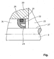
- the single FIGURE shows a schematic view of an embodiment of a shaft seal according to the invention 22.
- the shaft seal consists of a ring 22 made of PTFE (Teflon, registered trademark) and has a circumferential groove 26 in which an O-ring 21 is arranged.
- the shaft sealing ring presses against the surface 27 of the shaft 3 with an arcuate sealing lip 28.
- the shaft sealing ring is supported against the housing 20 and additionally produces a good static seal through the O-ring 21.
- the O-ring 21 is due to its bias and resilient contact force in addition to the attachment of the shaft seal.
- the media page 23 e.g. containing fuel, against the ambient side 24, e.g. against the atmosphere, sealed.
- Vitan registered trademark
- a costly chrome plating of the shaft is unnecessary in the starting region of the sealing lip 28, as it is otherwise necessary for some pumps.
- this seal is resistant to the overpressure that occurs when using a hand pump.
- the sealing lip 28 can be reinforced by a spring, which is proven especially in tumbling waves.
Landscapes
- Engineering & Computer Science (AREA)
- Mechanical Engineering (AREA)
- General Engineering & Computer Science (AREA)
- Rotary Pumps (AREA)
- Details And Applications Of Rotary Liquid Pumps (AREA)
Description
- Die vorliegende Erfindung betrifft eine Pumpe mit einem in einem Pumpengehäuse angeordneten Rotor, der über eine Antriebswelle drehangetrieben und dazu drehfest auf die Antriebswelle aufsteckbar ist, wobei zwischen dem Gehäuse und der Oberfläche der Welle ein Dichtring wirkt, der sich einerseits gegen die Oberfläche der Welle und andererseits gegen das Pumpengehäuse abstützt und sich somit gegen die Oberfläche der Welle presst,
- Pumpen unterschiedlichster Bauart, so beispielsweise Flügelzellenpumpen, sind aus der Praxis hinlänglich bekannt. Lediglich beispielhaft wird dazu auf die
DE 198 57 560 A1 verwiesen. - Pumpen der hier in Rede stehenden Art sind beispielsweise als Flügelzellen- oder Zahnradpumpen ausgebildet und dienen zur Förderung eines strömungsfähigen Mediums, nämlich von gasförmigen oder flüssigen Stoffen. Die Fördereinheit der Pumpe umfasst einen Rotor, der wiederum über eine Pumpenwelle angetrieben wird. Die Pumpenwelle ist innerhalb des Pumpengehäuses mit Hilfe von Lagern drehbar gehalten. Der Einfachheit halber wird die Pumpenwelle nachfolgend stets als Antriebswelle bezeichnet. Pumpen der gattungsbildenden Art werden u.a. zur Dieselförderung in Kraftfahrzeugen verwendet.
- Diese Probleme sind teilweise auch durch die im Stand der Technik verwendeten Wellendichtungen bedingt. Bei tiefen Temperaturen und erhöhtem Wellenschlag ist z.B. bei bekannten Elastomer-Radialwellendichtungen die Dichtwirkung nicht mehr gegeben.
- Aus der
DE 198 27 922 A ist eine gattungsbildende Pumpe bekannt. Diese Pumpe umfasst ein Pumpengehäuse und einen in dem Pumpengehäuse angeordneten Rotor, der über eine Antriebswelle drehangetrieben und dazu drehfest auf der Welle aufsteckbar ist. Zwischen dem Gehäuse und der Oberfläche der Welle wirkt ein Dichtring, der sich einerseits gegen die Oberfläche der Welle und andererseits gegen das Pumpengehäuse abstützt und somit gegen die Oberfläche der Welle presst. Eine ähnliche Pumpe ist auch aus derDE 197 17 295 A bekannt. Die dort vorgesehene Radialwellendichtung ist jedoch insbesondere im Temperaturverlauf, insbesondere bei niedrigen Temperaturen, unzureichend. - Der vorliegenden Erfindung liegt daher die Aufgabe zugrunde, eine Pumpe der gattungsbildenden Art derart auszugestalten und weiterzubilden, dass mit einfachen Mitteln eine hinreichend gute Radialwellendichtung geschaffen ist. Auch bei sehr niedrigen Temperaturen und bei erhöhtem Wellenschlag soll die Dichtwirkung hinreichend sein.
- Die voranstehende Aufgabe wird durch die Merkmale des Patentanspruchs 1 gelöst. Danach ist eine gattungsbildende Pumpe der eingangs genannten Art dadurch gekennzeichnet, dass der Dichtring einen Ringkörper mit einer umlaufenden Nut umfasst und dass in die umlaufende Nut ein O-Ring eingesetzt ist, dass der Ringkörper aus PTFE (Teflon) besteht und dass der Dichtring eine bogenförmige Dichtlippe umfasst, die sich gegen die Oberfläche der Welle presst.
- Mit der Radialwellendichtring aus PTFE (Teflon, eingetragene Marke) wird auch bei niedrigen Temperaturen und erhöhtem Wellenschlag eine gute Dichtwirkung erzielt. Außerdem kann auf eine Beschichtung bzw. Verchromung der Welle im Anlaufbereich des Radialwellendichtrings verzichtet werden, was wiederum Kosten spart. Auch ist die Verwendung von PTFE preisgünstiger als das sonst bekanntermaßen bei Kraftstoffen, wie Diesel oder Biodiesel (Rapsölmethylesther, RME) eingesetzte Vitan.
- Insbesondere ist die PTFE-Wellendichtung beim Einsatz von schlecht schmierenden oder aggressiven Medien, wie Kunststoff, von Vorteil. Als statische Dichtung und zur Befestigung kann ein zusätzlicher O-Ring dienen.
- Es gibt nun verschiedene Möglichkeiten, die Lehre der vorliegenden Erfindung in vorteilhafter Weise auszugestalten und weiterzubilden. Dazu ist einerseits auf den einzigen Patentanspruch, andererseits auf die nachfolgende Erläuterung eines Ausführungsbeispiels der Erfindung anhand der Zeichnung verwiesen. In Verbindung mit der Erläuterung des bevorzugten Ausführungsbeispiels der Erfindung anhand der Zeichnung werden auch im Allgemeinen bevorzugte Ausgestaltungen und Weiterbildungen der Lehre erläutert. In der Zeichnung zeigt
- die einzige Fig.
- in schematischer Ansicht ein Ausführungsbeispiel eines erfindungsgemäßen Wellendichtrings.
- Die einzige Figur zeigt in schematischer Ansicht ein Ausführungsbeispiels eines erfindungsgemäßen Wellendichtrings 22. Der Wellendichtring besteht aus einem Ring 22 aus PTFE (Teflon, eingetragene Marke) und besitzt eine umlaufende Nut 26, in der ein O-Ring 21 angeordnet ist. Der Wellendichtring presst sich mit einer bogenförmigen Dichtlippe 28 gegen die Oberfläche 27 der Welle 3. Auf der anderen Seite stützt sich der Wellendichtring gegen das Gehäuse 20 ab und stellt durch den O-Ring 21 zusätzlich eine gute statische Abdichtung her. Außerdem dient der O-Ring 21 durch seine Vorspannung und federnde Anpresskraft zusätzlich zur Befestigung des Wellendichtrings. Dabei wird die Medienseite 23, z.B. kraftstoffenthaltend, gegen die Umgebungsseite 24, z.B. gegen die Atmosphäre, abgedichtet.
- Im Gegensatz zu bekannten Wellendichtringen, die bei der hier verwendeten "gebauten" Welle 3 (Welle 3 wird an eine nicht dargestellte Nockenwelle eines Verbrennungsmotors montiert) und den dabei auftretenden größeren Spielen oder "Rundlauf-Schlägen" undicht werden, insbesondere bei tiefen Temperaturen, kann die erfindungsgemäße Dichtung mit einer sehr guten Dichtwirkung aufwarten, bei sonst gleicher Funktion und gleichem Bauraum.
- Ein teurer Werkstoff für Kraftstoffe wie Vitan (eingetragene Marke), ist nicht mehr notwendig. Auch erübrigt sich eine kostenintensive Verchromung der Welle im Anlaufbereich der Dichtlippe 28, wie sie ansonsten bei einigen Pumpen notwendig ist. Auch ist diese Dichtung gegen den Überdruck resistent, der beim Einsatz einer Handpumpe auftritt. Zusätzlich kann die Dichtlippe 28 durch eine Feder verstärkt werden, was sich vor allem bei taumelnden Wellen bewährt.
Claims (1)
- Pumpe mit einem in einem Pumpengehäuse (1) angeordneten Rotor (2), der über eine Antriebswelle (3) drehangetrieben und dazu drehfest auf die Antriebswelle (3) aufsteckbar ist, wobei zwischen dem Gehäuse (1) und der Oberfläche (27) der Welle (3) ein Dichtring (22) wirkt, der sich einerseits gegen die Oberfläche (27) der Welle (3) und andererseits gegen das Pumpengehäuse (1) abstützt und sich somit gegen die Oberfläche (27) der Welle (3) presst,
dadurch gekennzeichnet, dass der Dichtring (22) einen Ringkörper mit einer umlaufenden Nut (26) umfasst und dass in die umlaufende Nut (26) ein O-Ring (21) eingesetzt ist, dass der Ringkörper (22) aus PTFE (Teflon) besteht und dass der Dichtring (22) eine bogenförmige Dichtlippe (28) umfasst, die sich gegen die Oberfläche (27) der Welle (3) presst.
Applications Claiming Priority (2)
| Application Number | Priority Date | Filing Date | Title |
|---|---|---|---|
| DE10118720 | 2001-04-12 | ||
| DE2001118720 DE10118720A1 (de) | 2001-04-12 | 2001-04-12 | Pumpe |
Publications (2)
| Publication Number | Publication Date |
|---|---|
| EP1249609A1 EP1249609A1 (de) | 2002-10-16 |
| EP1249609B1 true EP1249609B1 (de) | 2008-04-09 |
Family
ID=7681678
Family Applications (1)
| Application Number | Title | Priority Date | Filing Date |
|---|---|---|---|
| EP20020006304 Expired - Lifetime EP1249609B1 (de) | 2001-04-12 | 2002-03-20 | Pumpe mit selbstzentrierender, einsteckbarer Antriebswelle |
Country Status (2)
| Country | Link |
|---|---|
| EP (1) | EP1249609B1 (de) |
| DE (2) | DE10118720A1 (de) |
Families Citing this family (3)
| Publication number | Priority date | Publication date | Assignee | Title |
|---|---|---|---|---|
| CH704333A2 (de) * | 2011-01-13 | 2012-07-13 | Mueller Haustechnik Ag M | Drehschieberpumpe zum Pumpen einer Flüssigkeit, insbesondere für ein Wasserklosett mit Unterdusche. |
| WO2018088148A1 (ja) * | 2016-11-10 | 2018-05-17 | 日本オイルポンプ株式会社 | ベーンポンプ |
| DE102023115059A1 (de) | 2023-06-07 | 2024-12-12 | B.Braun Avitum Ag | Aufsteck- und Sicherungsvorrichtung des Rotors einer peristaltischen Blutpumpe |
Family Cites Families (9)
| Publication number | Priority date | Publication date | Assignee | Title |
|---|---|---|---|---|
| JPS5478168A (en) * | 1977-12-02 | 1979-06-22 | Akitoshi Kitano | Vertical displacement type flow meter |
| US6036453A (en) * | 1995-05-09 | 2000-03-14 | Xolox Corporation | Pump assembly |
| JPH1054382A (ja) * | 1996-08-14 | 1998-02-24 | Mitsubishi Electric Corp | ベーン式真空ポンプ |
| DE19717295C2 (de) * | 1997-04-24 | 1999-09-23 | Danfoss As | Fluid-Maschine |
| JP3656205B2 (ja) * | 1997-06-25 | 2005-06-08 | 株式会社日立製作所 | パワーステアリング装置用油圧ポンプ |
| DE19857560A1 (de) | 1997-12-23 | 1999-06-24 | Luk Fahrzeug Hydraulik | Pumpe ohne eigene Lagerung |
| US6347843B1 (en) * | 1998-04-22 | 2002-02-19 | Denso Corporation | Pump equipment and method for assembling same |
| DE20022348U1 (de) * | 2000-04-18 | 2001-09-27 | Luk Fahrzeug-Hydraulik Gmbh & Co Kg, 61352 Bad Homburg | Pumpe |
| AU2001260058A1 (en) * | 2000-04-18 | 2001-10-30 | Luk Fahrzeug-Hydraulik Gmbh And Co. Kg | Pump |
-
2001
- 2001-04-12 DE DE2001118720 patent/DE10118720A1/de not_active Ceased
-
2002
- 2002-03-20 DE DE50212045T patent/DE50212045D1/de not_active Expired - Lifetime
- 2002-03-20 EP EP20020006304 patent/EP1249609B1/de not_active Expired - Lifetime
Also Published As
| Publication number | Publication date |
|---|---|
| DE10118720A1 (de) | 2002-10-17 |
| DE50212045D1 (de) | 2008-05-21 |
| EP1249609A1 (de) | 2002-10-16 |
Similar Documents
| Publication | Publication Date | Title |
|---|---|---|
| DE69210752T2 (de) | Exzenterantrieb für eine Verdrängermaschine | |
| EP1299662A1 (de) | Wellendichtring | |
| DE102004037419B3 (de) | Ventil für den Einsatz in einer kraftstoffführenden Leitung eines Kraftfahrzeuges | |
| EP1260712B1 (de) | Pumpe, insbesondere Plungerpumpe | |
| EP1286055A1 (de) | Nassläuferpumpe | |
| EP1041321B1 (de) | Gleitringdichtung | |
| EP1366789B1 (de) | Filterpatrone für flüssige, einfriergefährdete Medien, insbesondere für den Einsatz bei Brennstoffzellenfahrzeugen und bei Verbrennungskraftmaschinen, vorzugsweise Dieselmotoren | |
| EP2143935B1 (de) | Pumpeneinheit zur Förderung eines Fluids | |
| EP2314900B1 (de) | Ventileinrichtung | |
| DE10083436B4 (de) | Pumpe für ein flüssiges oder gasförmiges Medium | |
| EP1122472B1 (de) | Dichtsystem zwischen einer Welle und einem feststehenden Gehäuseteil | |
| EP2379890A2 (de) | Förderaggregat | |
| WO2010100021A2 (de) | Flügelzellenpumpe | |
| DE112016004887T5 (de) | Düsenantriebsmechanismus und turbolader | |
| EP3368801B1 (de) | Anordnung zur wellendichtung | |
| EP1775467A1 (de) | Schaltbarer Exzenterantrieb und Rührwerk mit zuschaltbarer Radialkolbenpumpe | |
| DE1653726A1 (de) | Elektromotorangetriebene Kreiselpumpe | |
| DE102015208643A1 (de) | Flügelzellenmaschine | |
| EP1274941A1 (de) | Pumpe | |
| EP1249609A1 (de) | Pumpe mit selbstzentrierender, einsteckbarer Antriebswelle | |
| DE3008491A1 (de) | Gleitringdichtung | |
| DE2813096A1 (de) | Behaelterpumpe | |
| DE102004051398B4 (de) | Axiallager für einen Rotor | |
| DE29810577U1 (de) | Gerotorpumpe für flüssige Medien | |
| DE102010041340A1 (de) | Spannstift |
Legal Events
| Date | Code | Title | Description |
|---|---|---|---|
| PUAI | Public reference made under article 153(3) epc to a published international application that has entered the european phase |
Free format text: ORIGINAL CODE: 0009012 |
|
| AK | Designated contracting states |
Kind code of ref document: A1 Designated state(s): AT BE CH CY DE DK ES FI FR GB GR IE IT LI LU MC NL PT SE TR |
|
| AX | Request for extension of the european patent |
Free format text: AL;LT;LV;MK;RO;SI |
|
| 17P | Request for examination filed |
Effective date: 20030322 |
|
| AKX | Designation fees paid |
Designated state(s): DE FR GB IT |
|
| 17Q | First examination report despatched |
Effective date: 20030617 |
|
| GRAP | Despatch of communication of intention to grant a patent |
Free format text: ORIGINAL CODE: EPIDOSNIGR1 |
|
| GRAC | Information related to communication of intention to grant a patent modified |
Free format text: ORIGINAL CODE: EPIDOSCIGR1 |
|
| RAP1 | Party data changed (applicant data changed or rights of an application transferred) |
Owner name: IXETIC BAD HOMBURG GMBH |
|
| GRAS | Grant fee paid |
Free format text: ORIGINAL CODE: EPIDOSNIGR3 |
|
| GRAA | (expected) grant |
Free format text: ORIGINAL CODE: 0009210 |
|
| AK | Designated contracting states |
Kind code of ref document: B1 Designated state(s): DE FR GB IT |
|
| REG | Reference to a national code |
Ref country code: GB Ref legal event code: FG4D Free format text: NOT ENGLISH |
|
| REF | Corresponds to: |
Ref document number: 50212045 Country of ref document: DE Date of ref document: 20080521 Kind code of ref document: P |
|
| ET | Fr: translation filed | ||
| PLBE | No opposition filed within time limit |
Free format text: ORIGINAL CODE: 0009261 |
|
| STAA | Information on the status of an ep patent application or granted ep patent |
Free format text: STATUS: NO OPPOSITION FILED WITHIN TIME LIMIT |
|
| 26N | No opposition filed |
Effective date: 20090112 |
|
| PGFP | Annual fee paid to national office [announced via postgrant information from national office to epo] |
Ref country code: DE Payment date: 20140331 Year of fee payment: 13 |
|
| PGFP | Annual fee paid to national office [announced via postgrant information from national office to epo] |
Ref country code: IT Payment date: 20140325 Year of fee payment: 13 |
|
| PGFP | Annual fee paid to national office [announced via postgrant information from national office to epo] |
Ref country code: GB Payment date: 20140320 Year of fee payment: 13 |
|
| REG | Reference to a national code |
Ref country code: DE Ref legal event code: R082 Ref document number: 50212045 Country of ref document: DE Representative=s name: RAUSCH, GABRIELE, DIPL.-PHYS. DR.RER.NAT., DE |
|
| REG | Reference to a national code |
Ref country code: DE Ref legal event code: R082 Ref document number: 50212045 Country of ref document: DE Representative=s name: RAUSCH, GABRIELE, DIPL.-PHYS. DR.RER.NAT., DE Effective date: 20140910 Ref country code: DE Ref legal event code: R081 Ref document number: 50212045 Country of ref document: DE Owner name: MAGNA POWERTRAIN BAD HOMBURG GMBH, DE Free format text: FORMER OWNER: IXETIC BAD HOMBURG GMBH, 61352 BAD HOMBURG, DE Effective date: 20140910 |
|
| PGFP | Annual fee paid to national office [announced via postgrant information from national office to epo] |
Ref country code: FR Payment date: 20140410 Year of fee payment: 13 |
|
| REG | Reference to a national code |
Ref country code: DE Ref legal event code: R119 Ref document number: 50212045 Country of ref document: DE |
|
| GBPC | Gb: european patent ceased through non-payment of renewal fee |
Effective date: 20150320 |
|
| PG25 | Lapsed in a contracting state [announced via postgrant information from national office to epo] |
Ref country code: IT Free format text: LAPSE BECAUSE OF NON-PAYMENT OF DUE FEES Effective date: 20150320 |
|
| REG | Reference to a national code |
Ref country code: FR Ref legal event code: ST Effective date: 20151130 |
|
| PG25 | Lapsed in a contracting state [announced via postgrant information from national office to epo] |
Ref country code: DE Free format text: LAPSE BECAUSE OF NON-PAYMENT OF DUE FEES Effective date: 20151001 Ref country code: GB Free format text: LAPSE BECAUSE OF NON-PAYMENT OF DUE FEES Effective date: 20150320 |
|
| PG25 | Lapsed in a contracting state [announced via postgrant information from national office to epo] |
Ref country code: FR Free format text: LAPSE BECAUSE OF NON-PAYMENT OF DUE FEES Effective date: 20150331 |