EP1249595A2 - Wärmeerzeuger für einen Stirlingmotor - Google Patents
Wärmeerzeuger für einen Stirlingmotor Download PDFInfo
- Publication number
- EP1249595A2 EP1249595A2 EP02008529A EP02008529A EP1249595A2 EP 1249595 A2 EP1249595 A2 EP 1249595A2 EP 02008529 A EP02008529 A EP 02008529A EP 02008529 A EP02008529 A EP 02008529A EP 1249595 A2 EP1249595 A2 EP 1249595A2
- Authority
- EP
- European Patent Office
- Prior art keywords
- heat generator
- generator according
- burner
- fuel
- combustion chamber
- Prior art date
- Legal status (The legal status is an assumption and is not a legal conclusion. Google has not performed a legal analysis and makes no representation as to the accuracy of the status listed.)
- Granted
Links
- 238000002485 combustion reaction Methods 0.000 claims abstract description 120
- 239000007789 gas Substances 0.000 claims abstract description 66
- 230000003647 oxidation Effects 0.000 claims abstract description 19
- 238000007254 oxidation reaction Methods 0.000 claims abstract description 19
- 239000000446 fuel Substances 0.000 claims description 86
- 238000000034 method Methods 0.000 claims description 24
- 239000003546 flue gas Substances 0.000 claims description 22
- 230000001105 regulatory effect Effects 0.000 claims description 9
- 238000012544 monitoring process Methods 0.000 claims description 7
- 238000005253 cladding Methods 0.000 claims description 4
- 238000009826 distribution Methods 0.000 claims description 4
- 230000033228 biological regulation Effects 0.000 claims description 3
- 239000007769 metal material Substances 0.000 claims description 2
- MWUXSHHQAYIFBG-UHFFFAOYSA-N nitrogen oxide Inorganic materials O=[N] MWUXSHHQAYIFBG-UHFFFAOYSA-N 0.000 abstract description 15
- UGFAIRIUMAVXCW-UHFFFAOYSA-N Carbon monoxide Chemical compound [O+]#[C-] UGFAIRIUMAVXCW-UHFFFAOYSA-N 0.000 description 13
- 241001156002 Anthonomus pomorum Species 0.000 description 9
- 230000006835 compression Effects 0.000 description 9
- 238000007906 compression Methods 0.000 description 9
- 238000012546 transfer Methods 0.000 description 6
- 230000015572 biosynthetic process Effects 0.000 description 5
- 238000013461 design Methods 0.000 description 4
- 239000000203 mixture Substances 0.000 description 4
- 241001295925 Gegenes Species 0.000 description 3
- 238000010438 heat treatment Methods 0.000 description 3
- 230000036316 preload Effects 0.000 description 3
- 230000008646 thermal stress Effects 0.000 description 3
- 238000006243 chemical reaction Methods 0.000 description 2
- 230000006378 damage Effects 0.000 description 2
- 238000001514 detection method Methods 0.000 description 2
- 238000010586 diagram Methods 0.000 description 2
- 230000002349 favourable effect Effects 0.000 description 2
- 238000009413 insulation Methods 0.000 description 2
- 125000006850 spacer group Chemical group 0.000 description 2
- 241001136792 Alle Species 0.000 description 1
- 238000005299 abrasion Methods 0.000 description 1
- 230000006978 adaptation Effects 0.000 description 1
- 230000009286 beneficial effect Effects 0.000 description 1
- 239000003054 catalyst Substances 0.000 description 1
- 238000004140 cleaning Methods 0.000 description 1
- 238000010276 construction Methods 0.000 description 1
- 230000007423 decrease Effects 0.000 description 1
- 230000001419 dependent effect Effects 0.000 description 1
- 238000011161 development Methods 0.000 description 1
- 230000018109 developmental process Effects 0.000 description 1
- 238000005516 engineering process Methods 0.000 description 1
- 238000004880 explosion Methods 0.000 description 1
- 238000010304 firing Methods 0.000 description 1
- 239000003517 fume Substances 0.000 description 1
- 229930195733 hydrocarbon Natural products 0.000 description 1
- 150000002430 hydrocarbons Chemical class 0.000 description 1
- 239000007788 liquid Substances 0.000 description 1
- 238000004519 manufacturing process Methods 0.000 description 1
- 230000009467 reduction Effects 0.000 description 1
- 238000007789 sealing Methods 0.000 description 1
- 239000000779 smoke Substances 0.000 description 1
- 239000004071 soot Substances 0.000 description 1
- 230000007704 transition Effects 0.000 description 1
Images


Classifications
-
- F—MECHANICAL ENGINEERING; LIGHTING; HEATING; WEAPONS; BLASTING
- F02—COMBUSTION ENGINES; HOT-GAS OR COMBUSTION-PRODUCT ENGINE PLANTS
- F02G—HOT GAS OR COMBUSTION-PRODUCT POSITIVE-DISPLACEMENT ENGINE PLANTS; USE OF WASTE HEAT OF COMBUSTION ENGINES; NOT OTHERWISE PROVIDED FOR
- F02G1/00—Hot gas positive-displacement engine plants
- F02G1/04—Hot gas positive-displacement engine plants of closed-cycle type
- F02G1/043—Hot gas positive-displacement engine plants of closed-cycle type the engine being operated by expansion and contraction of a mass of working gas which is heated and cooled in one of a plurality of constantly communicating expansible chambers, e.g. Stirling cycle type engines
- F02G1/053—Component parts or details
- F02G1/055—Heaters or coolers
-
- F—MECHANICAL ENGINEERING; LIGHTING; HEATING; WEAPONS; BLASTING
- F02—COMBUSTION ENGINES; HOT-GAS OR COMBUSTION-PRODUCT ENGINE PLANTS
- F02G—HOT GAS OR COMBUSTION-PRODUCT POSITIVE-DISPLACEMENT ENGINE PLANTS; USE OF WASTE HEAT OF COMBUSTION ENGINES; NOT OTHERWISE PROVIDED FOR
- F02G1/00—Hot gas positive-displacement engine plants
- F02G1/04—Hot gas positive-displacement engine plants of closed-cycle type
- F02G1/043—Hot gas positive-displacement engine plants of closed-cycle type the engine being operated by expansion and contraction of a mass of working gas which is heated and cooled in one of a plurality of constantly communicating expansible chambers, e.g. Stirling cycle type engines
-
- F—MECHANICAL ENGINEERING; LIGHTING; HEATING; WEAPONS; BLASTING
- F02—COMBUSTION ENGINES; HOT-GAS OR COMBUSTION-PRODUCT ENGINE PLANTS
- F02G—HOT GAS OR COMBUSTION-PRODUCT POSITIVE-DISPLACEMENT ENGINE PLANTS; USE OF WASTE HEAT OF COMBUSTION ENGINES; NOT OTHERWISE PROVIDED FOR
- F02G2243/00—Stirling type engines having closed regenerative thermodynamic cycles with flow controlled by volume changes
- F02G2243/02—Stirling type engines having closed regenerative thermodynamic cycles with flow controlled by volume changes having pistons and displacers in the same cylinder
-
- F—MECHANICAL ENGINEERING; LIGHTING; HEATING; WEAPONS; BLASTING
- F02—COMBUSTION ENGINES; HOT-GAS OR COMBUSTION-PRODUCT ENGINE PLANTS
- F02G—HOT GAS OR COMBUSTION-PRODUCT POSITIVE-DISPLACEMENT ENGINE PLANTS; USE OF WASTE HEAT OF COMBUSTION ENGINES; NOT OTHERWISE PROVIDED FOR
- F02G2243/00—Stirling type engines having closed regenerative thermodynamic cycles with flow controlled by volume changes
- F02G2243/30—Stirling type engines having closed regenerative thermodynamic cycles with flow controlled by volume changes having their pistons and displacers each in separate cylinders
- F02G2243/34—Regenerative displacers having their cylinders at right angle, e.g. "Robinson" engines
-
- F—MECHANICAL ENGINEERING; LIGHTING; HEATING; WEAPONS; BLASTING
- F02—COMBUSTION ENGINES; HOT-GAS OR COMBUSTION-PRODUCT ENGINE PLANTS
- F02G—HOT GAS OR COMBUSTION-PRODUCT POSITIVE-DISPLACEMENT ENGINE PLANTS; USE OF WASTE HEAT OF COMBUSTION ENGINES; NOT OTHERWISE PROVIDED FOR
- F02G2244/00—Machines having two pistons
- F02G2244/02—Single-acting two piston engines
- F02G2244/06—Single-acting two piston engines of stationary cylinder type
- F02G2244/10—Single-acting two piston engines of stationary cylinder type having cylinders in V-arrangement
-
- F—MECHANICAL ENGINEERING; LIGHTING; HEATING; WEAPONS; BLASTING
- F02—COMBUSTION ENGINES; HOT-GAS OR COMBUSTION-PRODUCT ENGINE PLANTS
- F02G—HOT GAS OR COMBUSTION-PRODUCT POSITIVE-DISPLACEMENT ENGINE PLANTS; USE OF WASTE HEAT OF COMBUSTION ENGINES; NOT OTHERWISE PROVIDED FOR
- F02G2270/00—Constructional features
- F02G2270/45—Piston rods
-
- F—MECHANICAL ENGINEERING; LIGHTING; HEATING; WEAPONS; BLASTING
- F02—COMBUSTION ENGINES; HOT-GAS OR COMBUSTION-PRODUCT ENGINE PLANTS
- F02G—HOT GAS OR COMBUSTION-PRODUCT POSITIVE-DISPLACEMENT ENGINE PLANTS; USE OF WASTE HEAT OF COMBUSTION ENGINES; NOT OTHERWISE PROVIDED FOR
- F02G2270/00—Constructional features
- F02G2270/50—Crosshead guiding pistons
Definitions
- the invention relates to a heat generator for one Stirling engine with a burner, with a combustion chamber, with a fuel supply, with a combustion air supply and with a heater, the heater and the combustion chamber by means of a casing tube and a housing against the Environment are sealed.
- the heat generator is used to drive the Stirling engine required thermal energy to the heater transfer. This will result in recirculation of the flue gases used to increase the proportion of nitrogen oxides in the flue gas reduce.
- the invention has for its object a heat generator to provide for a Stirling engine in which the Emission values further improved over a wide load range and especially the nitrogen oxides in the flue gas be reduced.
- This is supposed to be a flue gas cleaning for example by a catalyst.
- the heat generator has to be very compact.
- This task is for a heat generator for one Stirling engine with a burner, with a combustion chamber, with a fuel supply, with a combustion air supply and with a heater, the heater and the combustion chamber by means of a casing tube and a housing against the Environment are sealed, solved by the fact that between Burner and heater a mixing tube is arranged that between the burner outlet end and the burner end There is a recirculation gap at the end of the mixing tube, that the fuel supply is a first fuel lance and that the first fuel lance at least indirectly into one of the recirculation gap, burner and Mixing tube limited mixing zone opens according to the invention solved by using a heat generator for a Stirling engine a combustion chamber having at least one outlet, with a fuel supply, with a Combustion air supply, and with a heater, the Heater and the combustion chamber by means of a casing tube and a housing are sealed from the environment and wherein a mixing tube is arranged between the combustion chamber and the heater and between the outlet end of the combustion chamber and A recirculation
- the heat generator according to the invention it is possible to bring about a predominantly flameless oxidation of the fuel, which leads to drastic reductions in the nitrogen oxide content in the flue gases. It has been possible to use a heat generator according to the invention to reduce the emissions of NO x to 10 mg / m 3 , of CO to 20 mg / m 3 and the emissions of hydrocarbons or soot below the detection limit. All of this is possible without aftertreatment of the flue gases, so that the Stirling engine equipped with the heat generator according to the invention can be operated economically and nonetheless in an environmentally friendly manner.
- the heat generator according to the invention enables a power modulation of approximately 1: 3.5.
- the combustion air is heated to over 600 ° C and a large amount of flue gas recirculated so that the occurring Temperatures are significantly lower despite the air preheating than with combustion with flame formation. For this reason the formation of thermal nitrogen oxides is suppressed.
- the heat generator according to the invention is simple built so that the cost of producing the Heat generator according to the invention only slightly above those of a heat generator according to the prior art.
- fuel can be mixed into the Fresh air or pre-chamber mixing can be carried out.
- the Fuel guide has a second fuel lance that the second fuel lance opens into the pre-combustion chamber, and that an ignition device is provided in the pre-combustion chamber is, so that an automatic commissioning of the Heat generator is easily possible.
- the subsequent combustion with flame formation is used to heat the burner, the mixing tube and the Heater and the air preheater.
- the Recirculated flue gas temperature is sufficiently high the reaction of the fuel with the combustion air being able to maintain the first fuel lance opened so the flameless oxidation in the space between Fuel chamber and mixing tube can begin.
- opening the first fuel lance the second fuel lance is closed so that none There is more flame formation inside the burner.
- the first Fuel lance and the second fuel lance coaxial to execute each other.
- the mixing tube on his Outside diameter has a flange and that it is between the heater and the housing of the burner are clamped, and / or that the pre-combustion chamber and the mixing tube are braced against each other and / or that Combustion chamber mixing tube and heater clamped against the housing are. It has proven to be particularly advantageous highlighted when between combustion chamber and housing Bellows and / or a spring are provided, which the Cause tension.
- the ignition device spring-loaded Press the direction of thermal expansion against the pre-combustion chamber.
- the Compensation of thermal expansion can also be done with weights. These weights push all internals against the one below lying heater.
- a pressure difference that is already present in the heat generator can be used to compensate for thermal expansion.
- the burner is displaceable in the longitudinal direction Combustion chamber built-in. Due to the pressure difference between Air intake and combustion chamber, the burner acts like a piston and presses the internals against the heater. This will help the embodiment described below a Contact force of about 30N reached.
- Recuperator or a regenerator for preheating the Combustion air can be provided with the flue gases.
- recuperator or the regenerator results in a space-saving and efficient Design of the recuperator or the regenerator, if this is arranged concentrically with the combustion chamber Recuperator or the regenerator itself from the base plate up extends to the recirculation gap and when the recuperator or the regenerator in the radial direction from an inner one Cladding tube and an outer cladding tube is limited.
- Within of the recuperator are provided, which a Prevent the smoke gases from mixing with the combustion air and still a good heat transfer from the flue gas to the Ensure combustion air.
- Recuperators can be used in the heat generator according to the invention.
- recuperator is made of a metallic material.
- the mixing tube has a length of 2.5 x the diameter of the mixing tube to 8 x the diameter of the mixing tube, in particular of 3.6 x the diameter of the mixing tube and a cross-sectional area of 70 mm 2 / kW th to 400 mm 2 / kW th , in particular 160 mm 2 / kW th .
- the recirculation gap has an area of 200 mm 2 / kW th to 600 mm 2 / kW th , in particular 275 mm 2 / kW th .
- FIG. 1 For purposes of this specification, it has proven to be advantageous if the openings have a cross-sectional area of 7.5 mm 2 / kW th in total to 30 mm 2 / kW th , in particular 17 mm 2 / kW th .
- the nozzles with the longitudinal axis of the Heat generator an angle between 20 ° and 30 °, in particular 25 °.
- the operating behavior of the heat generator according to the invention in the start-up phase without flameless oxidation is improved if the fuel from the second fuel lance via a Distribution chamber and a pinhole in the pre-combustion chamber can flow, and / or the nozzles with their the Project the end facing away from the mixing zone into the pre-combustion chamber.
- the heat generator according to the invention can also be modulating be operated when the temperature of the heater is detected the pressure of the combustion air in the flow direction a combustion air fan is detected, the Amount of combustion air depending on the temperature of the Is regulated and the amount of gas depending on the heater Combustion air pressure with a constant pressure regulator is regulated. This procedure leaves an almost equally good one Modulation of the power of the heat generator too.
- the amount of gas by a Ratio pressure regulator or a constant pressure regulator regulated is, it being particularly advantageous if the Zero shift and / or the gain of the Ratio pressure regulator are adjustable.
- the amount of combustion air can be changed by changing the speed of a Blower or by changing the position of a throttle valve in the combustion air supply can be regulated.
- the temperature is at least one Temperature sensor, particularly preferably by two Temperature sensor, is monitored.
- the pressure in the pre-combustion chamber as the control pressure for the Gas control is used, it is particularly advantageous when the pressure in the pre-combustion chamber is determined by measuring the Pressure is detected in the second fuel lance, because in the Pre-combustion chamber the same pressure as in the second Fuel lance prevails, the temperatures in the switched off second fuel lance clearly are lower than in the pre-combustion chamber.
- Commissioning of the heat generator according to the invention takes place in that the heat generator through the second Fuel lance is brought to operating temperature, whereby the combustion in the second fuel lance by one known automatic burner controls is monitored. The transition on the flameless oxidation occurs as soon as the heat generator has reached its operating temperature. Then the second one Fuel lance switched off and the first fuel lance switched on so that there is a predominantly flameless Can form oxidation.
- the heat generator according to the invention can advantageously with the methods claimed in claims 27 to 38 operate.
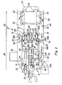
- the Stirling engine has a crankcase 1 in which one Crankshaft 3 is rotatably mounted. On a crank pin 5 Crankshaft 3 are a first connecting rod 7 and a second connecting rod 9 rotatably mounted.
- the first connecting rod 7 is over a first one Cross head 10 and a first piston rod 11 with a Compression piston 12 connected.
- the second connecting rod 9 is over a second cross head 13 and a second piston rod 14 with connected to a working piston 15.
- the constructive Design of compression pistons 12 and working pistons 15 is not important in connection with FIG. 1 and will therefore not explained in more detail here.
- the Compression piston 12 runs in a compression cylinder 16, during the working piston 15 in a working cylinder 17th running.
- the crankshaft 3 and the crank pin 5 are oil lubricated while the compression piston 12 and the Working piston 15 dry in the compression cylinder 16 or in Working cylinder 17 run.
- the working gas can be pushed back and forth.
- the working gas there takes the working gas, not shown in Fig. 1
- the regenerator 21 generally consists of a package of wire screens that are in Fig. 1 are not shown in detail.
- any Stirling engine can be used as a heat source Heat source with sufficient temperature level used 1 in the exemplary embodiment according to FIG Burner used (not shown), which is a gaseous or burn liquid fuel.
- the so-called The high temperature range of the Stirling engine is through a Thermal insulation 27 protected against heat loss.
- FIG. 2 is a heat generator according to the invention with a Burner 28 with a pre-combustion chamber 29 in partial longitudinal section shown.
- a combustion chamber 30 is connected to the burner 28 a mixing tube 31 and the heater 23.
- heater 23 the heat of the flue gases 59 to that not shown Transfer the working gas of the Stirling engine.
- the fuel will be supplied via a fuel supply 33.
- Be outside Burner 28 and combustion chamber 30 from a casing tube 35 and only partially shown housing 37 with a base plate 39 limited.
- the burner 28 is longitudinally displaceable on the Base plate 39 attached.
- the fuel supply 33 consists of a first one Fuel lance 41 and a second coaxially arranged Fuel lance 43.
- the first fuel lance 41 opens outside the pre-combustion chamber 29 in a mixing zone 45, which on the one hand from the pre-combustion chamber 29 and on the other hand from a cover plate 46 is limited.
- the second fuel lance 43 opens out over several Outlet openings 47 in a distribution chamber 48
- Pinhole 49 is the distribution chamber 48 from the actual one Pre-combustion chamber 29 separated.
- the combustion air which in Fig. 2 is indicated by the arrows 51, also flows in the pre-combustion chamber 29.
- the fuel mixes after the Flowing through the pinhole 49 with the combustion air an ignitable mixture.
- By an ignition device 53 can this ignitable mixture will ignite and burn in the pre-combustion chamber 29 to form a flame.
- the flue gas flows out of the pre-combustion chamber 29 via nozzles 55 as through Arrows 57 is indicated in the mixing zone 45 and that Mixing tube 31. After flowing through the mixing tube 31 the flue gases, which are indicated by the number 59 provided arrows are indicated by the heater 23 performed after it has previously been deflected by the housing 37 are.
- the first fuel lance 41 is opened, which via Openings 65, a collection space 66 and openings 67 in the Mixing zone 45 between pre-combustion chamber 29 and mixing tube 31 opens.
- flue gases 59a and that in FIG. 2 are not shown fuel, which through the openings 67 in the mixing zone 45 emerges mainly within of the mixing tube 31 takes place flameless oxidation.
- the second Fuel lance 43 are closed so that none Flame formation in the pre-combustion chamber 29 occurs more. In this The normal operating state flows through the combustion air 51 Precombustion chamber 29 without getting fuel in it mix.
- the mixing of fuel and Combustion air only takes place in the mixing zone 45 and in the mixing tube 31.
- the nozzles 55 can also be used as Venturi or Laval nozzles be trained.
- the one at the location of the highest air speed prevailing pressure is less than the gas pressure of a public gas network, which is about 18 to 22 mbar.
- This Differential pressure can be exploited to the gas interfere.
- the openings 67 are shifted in such a way that them directly in the nozzles 55 at the location of the highest Air velocity flow.
- a direct Connection between the openings 67 and the openings 65 of the first fuel lance 41 are produced. That is, the Collection space 66 can be omitted.
- Heat generator can be achieved.
- burner 28 mixing tube 31 and heater 23 against the housing 37 or the base plate 39 of the housing braced.
- the preload is made from a metallic one Bellows 71, which is on the one hand against the base plate 39 supports and on the other hand connected to the pre-combustion chamber 29 is upset.
- the preload is over at the perimeter distributed spacer plates 73, of which only one in FIG. 2 is shown, transferred to the mixing tube.
- the biasing force can also be added by a spring 74 be applied.
- the burner is replaced by the Pressure difference between the environment and the interior of the burner braced.
- a flange 75 is arranged, the first Biasing force from the mixing tube via the heater 23 to the Transmits housing 37 and on the other hand forces the flue gas 59 to flow through the heater 23.
- the ignition device 53 will by a spring 77, which is located at one end on the base plate 39 and at the other end on a sleeve of the ignition device 53 supports, pressed against the pre-combustion chamber 29.
- a Thermal insulation which is arranged in and around the burner not shown in Fig. 2 for reasons of clarity.
- the Recirculation gap 61 is between 20 and 35 mm wide, the Length of the mixing tube is about 350 mm and the diameter of the mixing tube 31 is approximately 90 mm.
- the flue gas 59 leaves the mixing tube 31 is approximately at a temperature of about 1,200 ° C to 1,400 ° C and is cooled by heat transfer in the heater 23 to approximately 850 0 Celsius.
- the temperature of the working gas in the heater 23 is on average about 650 ° Celsius.
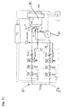
- FIG. 3a, 3b and 3c is a block diagram of a heat generator according to the invention, which here in its Entire is designated by the reference numeral 83, and its gas supply, consisting of a starting gas line 85 and a main gas section 87.
- Figures 3a-c differ only in the Control pressure supplies to the pressure regulator of the main gas ramp 87 shown. With everyone in the fig. 3a, 3b and 3c shown control pressure supplies is a modulating Operation of the heat generator 83 according to the invention possible. There are slight differences in terms of Modulation ability and other operating parameters as well as the Costs.
- the starting gas line 85 into the second Fuel lance 43 opens and the main gas route 87 in the first fuel lance 41 opens.
- the flue gas leaves the Heat generator 53 at the point indicated by arrow 59.
- the combustion air, which is indicated by the arrow 51 in FIG. 3 is indicated, the heat generator 83 by a fan 89 fed.
- a control unit 91 is used to control the Heat generator 83 and to control a Monitoring module 93.
- the starting gas line 85 and the Main gas route 87 are from the monitoring module 93 driven.
- the heat generator 83 If the heat generator 83 is to be put into operation, gives the control unit 91 a corresponding signal to the Monitoring module 93 further, which thereupon the Starting gas line 85 turns on. Signal connections are in 3a - c indicated by dashed lines.
- the Starting gas route 85 consists of two series connected Main valves with which the gas supply to the second Fuel lance 43 can be switched on or off. A pressure regulator is then provided.
- the pressure regulator can be used as a constant pressure regulator or as a ratio pressure regulator be executed. Depending on the version of the pressure regulator, a adjustable throttle of the starting gas line.
- the pressure regulator of the start gas ramp 85 is connected to the outlet of the blower 89 via a first control line 95. This means that the pressure of the combustion air downstream of the blower 89 is used as the control pressure for the pressure regulator of the starting gas line.
- the second fuel lance is ignited and the combustion is monitored via a conventional automatic burner control integrated in the monitoring module 93.
- the starting gas ramp 85 can also be designed as a so-called compact fitting.
- the main gas ramp 87 is constructed in the same way as the start gas ramp, namely it consists of two main valves, a pressure regulator and optionally a throttle.
- the pressure regulator can be designed as a constant pressure regulator or ratio pressure regulator.
- Fig. 3a is the control pressure of the pressure control valve Main gas ramp 87 the pressure in the start gas ramp 85 downstream of the main valves. If the Main gas ramp 87 is in operation, the main valves are the Start gas ramp 85 closed, so that the downstream Main valves in the start gas ramp 85 the same pressure as in the second fuel lance 43 and in the pre-combustion chamber 29 prevails (see also Fig. 2). Because the temperatures of the Start gas ramp 85 where the control pressure for the pressure regulator the main gas ramp via a second control line 97 is significantly lower than in the pre-combustion chamber 29 the detection of the pressure of the start gas ramp 85 easier and more reliable than when the pressure is directly in the Pre-combustion chamber 29 would be removed.
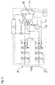
- Fig. 3b an alternative is shown in which the Control pressure of the main gas ramp 87 via a third Control line 99 and the first control line 95 downstream of the blower 89 is detected.
- third control line 99 did not require a high one Exposed to temperatures. Still is a modulating Operation possible without further notice, the Modulation range compared to the exemplary embodiment according to FIG. 3a is somewhat restricted.
- 3c shows a third alternative in which a fourth control line 101 controls the pressure in the combustion chamber 30 (see 2) of the heat generator 83 is detected. This pressure serves as the control pressure of the main gas ramp 87. Also in this The embodiment is a modulating firing mode without further ado possible.
- Adapting the requested heat output is a on the heater second temperature sensor 103 arranged.
- the output signal of the second temperature sensor 103 is sent to the control unit 91 forwarded. If the from the second temperature sensor 103 detected temperature rises, it means that from the heater 23 less heat is removed, so that the control unit 91 can reduce the speed of the fan 89 so that the Combustion air volume is reduced. Alternatively, too a throttle valve to be closed a little further to the from Blower 89 in the heat generator 83 delivered amount of air reduce.
- the throttle valve is not in Fig. 3a, 3b and 3c shown.
Landscapes
- Engineering & Computer Science (AREA)
- Chemical & Material Sciences (AREA)
- Combustion & Propulsion (AREA)
- Mechanical Engineering (AREA)
- General Engineering & Computer Science (AREA)
- Combustion Of Fluid Fuel (AREA)
Abstract
Description
- Erfassen der Temperatur des Erhitzers,
- Erfassen des Drucks der vorgewärmten Verbrennungsluft, Regeln der Verbrennungsluftmenge in Abhängigkeit der Temperatur des Erhitzers und
- Regeln der Gasmenge in Abhängigkeit des Drucks der vorgewärmten Verbrennungsluft.
- Figur 1
- einen Querschnitt durch einen 90°-V2-Stirlingmotor, der mit einem erfindungsgemäßen Wärmeerzeuger ausgerüstet ist,
- Figur 2
- einen Teillängsschnitt durch einen erfindungsgemäßen Wärmeerzeuger und
- Fig. 3a-c
- ein Blockschaltbild eines erfindungsgemäßen Wärmeerzeugers inklusive Gas und Verbrennungsluftversorgung.
Claims (41)
- Modulationsfähiger Wärmeerzeuger mit überwiegend flammloser Oxidation für einen Stirlingmotor, mit einem Brenner (28), mit einer Brennkammer (30), mit einer Brennstoffzuführung (33), mit einer Verbrennungsluftzuführung und mit einem Erhitzer (23), wobei der Erhitzer (23) und die Brennkammer (30) mittels eines Mantelrohrs (35) und eines Gehäuses (37) gegen die Umgebung abgedichtet sind, dadurch gekennzeichnet, dass zwischen Brenner (28) und Erhitzer (23) ein Mischrohr (31) angeordnet ist, dass zwischen auslassseitigem Ende des Brenners (28) und brennkammerseitigem Ende (69) des Mischrohrs (31) ein Rezirkulationsspalt (61) vorhanden ist, dass die Brennstoffzuführung (33) eine erste Brennstofflanze (41) aufweist, und dass die erste Brennstofflanze (41) mindestens mittelbar in eine vom Rezirkulationsspalt (61), Brenner (28) und Mischrohr (31) begrenzte Vermischungszone (45) mündet.
- Wärmeerzeuger nach Anspruch 1, dadurch gekennzeichnet, dass die Brennstoffzuführung (33) eine zweite Brennstofflanze (43) aufweist, dass die zweite Brennstofflanze (43) mindestens mittelbar in eine Vorbrennkammer (29) des Brenners (28) mündet, und dass in der Vorbrennkammer (29) eine Zündeinrichtung (53) vorgesehen ist.
- Wärmeerzeuger nach Anspruch 2, dadurch gekennzeichnet, dass die erste Brennstofflanze (41) und die zweite Brennstofflanze (43) koaxial zueinander angeordnet sind.
- Wärmeerzeuger nach einem der vorhergehenden Ansprüche, dadurch gekennzeichnet, dass das Mischrohr (31) an seinem Außendurchmesser einen Flansch (75) aufweist, und dass der Erhitzer (23) zwischen dem Flansch (75) und dem Gehäuse (37) eingespannt ist.
- Wärmeerzeuger nach einem der vorhergehenden Ansprüche, dadurch gekennzeichnet, dass der Brenner (28) und das Mischrohr (31) gegeneinander verspannt sind.
- Wärmeerzeuger nach einem der vorhergehenden Ansprüche, dadurch gekennzeichnet, dass Brenner (28), Mischrohr (31) und Erhitzer (23) gegen das Gehäuse (37) verspannt sind.
- Wärmeerzeuger nach Anspruch 5 oder 6, dadurch gekennzeichnet, dass zwischen Brenner (28) und Gehäuse (37) ein Faltenbalg (71) vorgesehen ist, und dass der Faltenbalg (71) die Verspannung bewirkt.
- Wärmeerzeuger nach einem der Ansprüche 5 bis 7, dadurch gekennzeichnet, dass zwischen Brenner (28) und Gehäuse (37) eine Feder (74) vorgesehen ist, und dass die Feder (74) die Verspannung bewirkt.
- Wärmeerzeuger nach einem der vorhergehenden Ansprüche, dadurch gekennzeichnet, dass die Brennstoffzuführung (33) mit einer Grundplatte (39) des Gehäuses (37) fest verbunden und in Richtung der Wärmedehnung relativ zum Brenner (28) verschiebbar ist.
- Wärmeerzeuger nach einem der Ansprüche 1 bis 8, dadurch gekennzeichnet, dass die Brennstoffzuführung (33) mit dem Brenner (28) fest verbunden und in Richtung der Wärmedehnung relativ zur Grundplatte (39) verschiebbar ist.
- Wärmeerzeuger nach einem der vorhergehenden Ansprüche, dadurch gekennzeichnet, dass die Zündeinrichtung (53) federbelastet in Richtung der Wärmedehnung gegen den Brenner (28) oder eine am Brenner (28) angeordnete Hülse gepresst wird.
- Wärmeerzeuger nach einem der vorhergehenden Ansprüche, dadurch gekennzeichnet, dass eine Längsachse des Wärmeerzeugers vertikal angeordnet ist, und dass zur Kompensation der Wärmedehnungen die Gewichtskraft des Wärmeerzeugers ausgenutzt wird.
- Wärmeerzeuger nach einem der vorhergehenden Ansprüche, dadurch gekennzeichnet, dass der Brenner in Längsrichtung verschiebbar in der Brennkammer eingebaut wird.
- Wärmeerzeuger nach einem der vorhergehenden Ansprüche, dadurch gekennzeichnet, dass ein Rekuperator (63) oder ein Regenerator zur Vorwärmung der Verbrennungsluft (51) mit den Rauchgasen vorgesehen ist.
- Wärmeerzeuger nach Anspruch 14, dadurch gekennzeichnet, dass der Rekuperator (63) oder der Regenerator konzentrisch zum Brenner (28) angeordnet ist, dass der Rekuperator (63) sich von der Grundplatte (39) bis zum Rezirkulationspalt (61) erstreckt, und dass der Rekuperator (63) in radialer Richtung von einem inneren Hüllrohr und einem äußeren Hüllrohr begrenzt wird.
- Wärmeerzeuger nach Anspruch 14 oder 15, dadurch gekennzeichnet, dass der Rekuperator (63) oder der Regenerator aus einem metallischem Werkstoff besteht.
- Wärmeerzeuger nach einem der vorhergehenden Ansprüche, dadurch gekennzeichnet, dass das Mischrohr (31) eine Länge von 2,5 x Durchmesser Mischrohr bis 8 x Durchmesser Mischrohr , insbesondere von 3,6 x Durchmesser Mischrohr aufweist.
- Wärmeerzeuger nach einem der vorhergehenden Ansprüche, dadurch gekennzeichnet, dass das Mischrohr (31) eine Querschnittsfläche von 970 mm2/kWth bis 400 mm2/kWth, insbesondere 160 mm2/kWth, aufweist.
- Wärmeerzeuger nach einem der vorhergehenden Ansprüche, dadurch gekennzeichnet, dass der Rezirkulationsspalt (61) eine Fläche von 200 mm2/kWth bis 600 mm2/kWth, insbesondere 275 mm2/kWth, aufweist.
- Wärmeerzeuger nach einem der vorhergehenden Ansprüche, dadurch gekennzeichnet, dass die Verbrennungsluftzuführung über eine oder mehrere in die Vermischungszone (45) gerichtete Düsen (55) erfolgt.
- Wärmeerzeuger nach Anspruch 20, dadurch gekennzeichnet, dass die erste Brennstofflanze (41) Brennstoff über Öffnungen (65, 67) in die Vermischungszone (45) einbringt.
- Wärmeerzeuger nach einem der vorhergehenden Ansprüche, dadurch gekennzeichnet, dass die Öffnungen (65, 67) eine Querschnittsfläche von in der Summe 0,7 mm2/kWth bis 3,5 mm2/kWth, insbesondere 2,5 mm2/kWth, aufweisen.
- Wärmeerzeuger nach einem der Ansprüche 20 bis 22, dadurch gekennzeichnet, dass die Düsen (55) als Venturi- oder Laval-Düsen ausgebildet sind, und dass die erste Brennstofflanze (41) den Brennstoff in die Düsen (55) einbringt.
- Wärmeerzeuger nach einem der Ansprüche 20 bis 23, dadurch gekennzeichnet, dass die Düsen (55) eine Querschnittsfläche von 7,5 mm2/kWtherm bis 30 mm2/kWtherm, insbesondere 17 mm2/kWtherm, aufweisen.
- Wärmeerzeuger nach einem der vorhergehenden Ansprüche, dadurch gekennzeichnet, dass die Düsen (55) mit der Längsachse des Wärmeerzeugers einen Winkel zwischen 20° und 30°, insbesondere 25°, einschließen.
- Wärmeerzeuger nach einem der vorhergehenden Ansprüche, dadurch gekennzeichnet, dass der Brennstoff aus der zweiten Brennstofflanze über eine Verteilkammer und eine Lochblende in die Vorbrennkammer strömen kann.
- Wärmeerzeuger nach einem der Ansprüche 20 bis 26, dadurch gekennzeichnet, dass die Düsen (55) mit ihrem der Vermischungszone (45) abgewandten Ende in die Vorbrennkammer (29) ragen.
- Verfahren zum Betreiben eines Wärmeerzeugers nach einem der vorhergehenden Ansprüche, gekennzeichnet durch folgende Verfahrensschritte:Erfassen der Temperatur des Erhitzers (23),Erfassen des Drucks der vorgewärmten Verbrennungsluft,Regeln der Verbrennungsluftmenge in Abhängigkeit der Temperatur des Erhitzers (23) undRegeln der Gasmenge in Abhängigkeit des Drucks der vorgewärmten Verbrennungsluft.
- Verfahren nach Anspruch 28, dadurch gekennzeichnet, dass der Druck der Verbrennungsluft in der Vorbrennkammer (29) oder im Brennraum (30) erfasst wird.
- Verfahren zum Betreiben eines Wärmeerzeugers nach einem der vorhergehenden Ansprüche, gekennzeichnet durch folgende Verfahrensschritte:Erfassen der Temperatur des Erhitzers (23),Erfassen des Drucks der Verbrennungsluft in Strömungsrichtung nach einem Gebläse (),Regeln der Verbrennungsluftmenge in Abhängigkeit der Temperatur des Erhitzers (23) undRegeln der Gasmenge in Abhängigkeit des Drucks der Verbrennungsluft.
- Verfahren nach einem der Ansprüche 28 bis 30, dadurch gekennzeichnet, dass die Gasmenge durch einen Verhältnisdruckregler () oder einen Gleichdruckregler geregelt wird.
- Verfahren nach Anspruch 31, dadurch gekennzeichnet, dass die Nullpunktverschiebung und/oder die Verstärkung des Verhältnisdruckreglers () einstellbar sind.
- Verfahren nach einem der Ansprüche 28 bis 32, dadurch gekennzeichnet, dass die Verbrennungsluftmenge durch Ändern der Drehzahl eines Gebläses () geregelt wird.
- Verfahren nach einem der Ansprüche 28 bis 33, dadurch gekennzeichnet, dass die Verbrennungsluftmenge durch Ändern der Stellung einer Drosselklappe in einer Verbrennungsluftzufuhr () geregelt wird.
- Verfahren nach einem der Ansprüche 28 bis 34, dadurch gekennzeichnet, dass die flammlose Oxidation im Mischrohr (31) durch mindestens einen Temperaturfühler (64) überwacht wird.
- Verfahren nach einem der Ansprüche 28 bis 35, dadurch gekennzeichnet, dass der Druck in der Vorbrennkammer (29) durch eine Messung des Drucks in der zweiten Brennstofflanze (43) erfasst wird.
- Verfahren nach einem der Ansprüche 28 bis 36, dadurch gekennzeichnet, dass der Wärmeerzeuger durch die zweite Brennstofflanze (43) auf Betriebstemperatur gebracht wird.
- Verfahren nach Anspruch 37, dadurch gekennzeichnet, dass die Verbrennung in der zweiten Brennstofflanze (43) durch einen Feuerungsautomaten () überwacht wird.
- Verfahren nach einem der Ansprüche 28 bis 38, dadurch gekennzeichnet, dass die zweite Brennstofflanze (43) abgeschaltet wird, und dass die erste Brennstofflanze (41) eingeschaltet wird, wenn der Wärmeerzeuger seine Betriebstemperatur erreicht hat.
- Verfahren nach einem der Ansprüche 28 bis 39, dadurch gekennzeichnet, dass ein redundant aufgebautes, insbesondere ein zwei Mikrocontroller aufweisendes Überwachungsmodul () die Durchführung des Verfahrens nach einem der Ansprüche 27 bis 38 überwacht und beim Auftreten eines Fehlers ein entsprechendes Alarmsignal abgibt und/oder den Wärmeerzeuger abschaltet.
- Steuergerät für einen Wärmeerzeuger, dadurch gekennzeichnet, dass es zur Durchführung eines der Verfahren nach den Ansprüchen 28 bis 40 geeignet ist.
Applications Claiming Priority (2)
| Application Number | Priority Date | Filing Date | Title |
|---|---|---|---|
| DE10118546 | 2001-04-14 | ||
| DE2001118546 DE10118546A1 (de) | 2001-04-14 | 2001-04-14 | Wärmeerzeuger für einen Stirlingmotor |
Publications (3)
| Publication Number | Publication Date |
|---|---|
| EP1249595A2 true EP1249595A2 (de) | 2002-10-16 |
| EP1249595A3 EP1249595A3 (de) | 2003-05-28 |
| EP1249595B1 EP1249595B1 (de) | 2007-01-10 |
Family
ID=7681548
Family Applications (1)
| Application Number | Title | Priority Date | Filing Date |
|---|---|---|---|
| EP20020008529 Expired - Lifetime EP1249595B1 (de) | 2001-04-14 | 2002-04-15 | Wärmeerzeuger für einen Stirlingmotor |
Country Status (2)
| Country | Link |
|---|---|
| EP (1) | EP1249595B1 (de) |
| DE (2) | DE10118546A1 (de) |
Family Cites Families (5)
| Publication number | Priority date | Publication date | Assignee | Title |
|---|---|---|---|---|
| US3918262A (en) * | 1974-09-05 | 1975-11-11 | Ford Motor Co | Hot exhaust gas recirculating system for a stirling engine |
| US4277942A (en) * | 1979-02-28 | 1981-07-14 | Kommanditbolaget United Stirling | Exhaust gas recirculation apparatus |
| EP0463218B1 (de) * | 1990-06-29 | 1994-11-23 | Joachim Dr.-Ing. Wünning | Verfahren und Vorrichtung zum Verbrennen von Brennstoff in einem Verbrennungsraum |
| DE4430267A1 (de) * | 1994-08-26 | 1996-02-29 | Bosch Gmbh Robert | Brenner zur flammenlosen Verbrennung eines Brenngas-Luftgemisches |
| DE19925715A1 (de) * | 1999-06-07 | 2000-12-14 | Heinrich Koehne | Verfahren und Vorrichtung zur homogenen Vermischung von Verbrennungsluft und Verbrennungsabgasen |
-
2001
- 2001-04-14 DE DE2001118546 patent/DE10118546A1/de not_active Withdrawn
-
2002
- 2002-04-15 EP EP20020008529 patent/EP1249595B1/de not_active Expired - Lifetime
- 2002-04-15 DE DE50209207T patent/DE50209207D1/de not_active Expired - Lifetime
Non-Patent Citations (1)
| Title |
|---|
| ""Stirlingmaschinentechnik"", C.F. MOLLER VERLAG, HEIDELBERG, pages: 192 - 194 |
Also Published As
| Publication number | Publication date |
|---|---|
| EP1249595A3 (de) | 2003-05-28 |
| DE50209207D1 (de) | 2007-02-22 |
| DE10118546A1 (de) | 2002-10-24 |
| EP1249595B1 (de) | 2007-01-10 |
Similar Documents
| Publication | Publication Date | Title |
|---|---|---|
| EP0463218B1 (de) | Verfahren und Vorrichtung zum Verbrennen von Brennstoff in einem Verbrennungsraum | |
| DE60124508T2 (de) | Verfahren zur regelung der kraftstoff- und luftzufuhr zu einem brenner eines thermozyklusmotors | |
| CH704829A2 (de) | Gasturbogruppe und zugehöriges Betriebsverfahren. | |
| EP0307538A2 (de) | Feuerungseinrichtung | |
| WO2012107013A2 (de) | Axialkolbenmotor sowie verfahren zum betrieb eines axialkolbenmotors | |
| DE3102165A1 (de) | Brenner-kesselkombination mit verbessertem brenner und verbrennungsverfahren | |
| EP1113158A2 (de) | Verbrennungsmotor | |
| EP2179141B1 (de) | Wärmekraftmaschine | |
| EP1249595B1 (de) | Wärmeerzeuger für einen Stirlingmotor | |
| DE102010046733A1 (de) | Ölvormischbrenner | |
| EP1533494A2 (de) | Kraftfahrzeug mit Verbrennungsmotor und Hilfsaggregat | |
| EP3048244B1 (de) | Axialkolbenmotor | |
| DE2439873A1 (de) | Verfahren und vorrichtung zum erzeugen wasserstoffreichen gases | |
| DE3906976C2 (de) | ||
| EP0227637B1 (de) | Ölbrenner | |
| DE2410948C3 (de) | Brennkraftmaschinen-Arbeitsverfahren und nach diesem Verfahren arbeitende Brennkraftmaschinenanlage | |
| AT410699B (de) | Arbeitsverfahren einer brennkraftmaschine und brennkraftmaschine | |
| DE102005037540B3 (de) | Kraft-Wärme-Kopplungsanlage | |
| DE4438356C2 (de) | Verfahren und Vorrichtung zur zweistufigen Verbrennung von gas- oder dampfförmigem Brennstoff | |
| DE3145073A1 (de) | Hubkolbenmotor mit vorrichtungen zur bildung von brennstoffaerosole | |
| EP1092851A2 (de) | Verbrennungsmotor sowie Verfahren zum Betreiben einer Verbrennungskraftmaschine | |
| WO2011009451A2 (de) | Axialkolbenmotor, verfahren zum betrieb eines axialkolbenmotors sowie verfahren zur herstellung eines wärmeübertragers eines axialkolbenmotors | |
| DE2543761A1 (de) | Verfahren zum thermischen nachverbrennen von brennbare fremdkoerper, fluessigkeitsteilchen oder gasfoermige schadstoffe enthaltender abluft aus industriellen arbeitsanlagen, wie trockenkammern o.dgl., und vorrichtung zur durchfuehrung dieses verfahrens | |
| DE654416C (de) | Kolbenbrennkraftmaschine mit aeusserer Verbrennung, bei der verdichtete sauerstoffhaltige Gase oder Gasgemische in Brennkammern mit Brennstoff verbrannt und so Druckgaseerzeugt werden | |
| EP0567865A2 (de) | Rekuperationsbrenner für einen Ofen |
Legal Events
| Date | Code | Title | Description |
|---|---|---|---|
| PUAI | Public reference made under article 153(3) epc to a published international application that has entered the european phase |
Free format text: ORIGINAL CODE: 0009012 |
|
| AK | Designated contracting states |
Kind code of ref document: A2 Designated state(s): AT BE CH CY DE DK ES FI FR GB GR IE IT LI LU MC NL PT SE TR |
|
| AX | Request for extension of the european patent |
Free format text: AL;LT;LV;MK;RO;SI |
|
| PUAL | Search report despatched |
Free format text: ORIGINAL CODE: 0009013 |
|
| AK | Designated contracting states |
Designated state(s): AT BE CH CY DE DK ES FI FR GB GR IE IT LI LU MC NL PT SE TR |
|
| AX | Request for extension of the european patent |
Extension state: AL LT LV MK RO SI |
|
| 17P | Request for examination filed |
Effective date: 20031125 |
|
| AKX | Designation fees paid |
Designated state(s): AT BE CH CY DE DK ES FI FR GB GR IE IT LI LU MC NL PT SE TR |
|
| RAP1 | Party data changed (applicant data changed or rights of an application transferred) |
Owner name: SOLO STIRLING GMBH |
|
| 111Z | Information provided on other rights and legal means of execution |
Free format text: ATBECHCYDEDKESFIFRGBGRIEITLILUMCNLPTSETR Effective date: 20050112 |
|
| GRAP | Despatch of communication of intention to grant a patent |
Free format text: ORIGINAL CODE: EPIDOSNIGR1 |
|
| GRAS | Grant fee paid |
Free format text: ORIGINAL CODE: EPIDOSNIGR3 |
|
| GRAA | (expected) grant |
Free format text: ORIGINAL CODE: 0009210 |
|
| AK | Designated contracting states |
Kind code of ref document: B1 Designated state(s): AT BE CH CY DE DK ES FI FR GB GR IE IT LI LU MC NL PT SE TR |
|
| PG25 | Lapsed in a contracting state [announced via postgrant information from national office to epo] |
Ref country code: FI Free format text: LAPSE BECAUSE OF FAILURE TO SUBMIT A TRANSLATION OF THE DESCRIPTION OR TO PAY THE FEE WITHIN THE PRESCRIBED TIME-LIMIT Effective date: 20070110 Ref country code: NL Free format text: LAPSE BECAUSE OF FAILURE TO SUBMIT A TRANSLATION OF THE DESCRIPTION OR TO PAY THE FEE WITHIN THE PRESCRIBED TIME-LIMIT Effective date: 20070110 Ref country code: IE Free format text: LAPSE BECAUSE OF FAILURE TO SUBMIT A TRANSLATION OF THE DESCRIPTION OR TO PAY THE FEE WITHIN THE PRESCRIBED TIME-LIMIT Effective date: 20070110 Ref country code: DK Free format text: LAPSE BECAUSE OF FAILURE TO SUBMIT A TRANSLATION OF THE DESCRIPTION OR TO PAY THE FEE WITHIN THE PRESCRIBED TIME-LIMIT Effective date: 20070110 |
|
| REG | Reference to a national code |
Ref country code: GB Ref legal event code: FG4D Free format text: NOT ENGLISH |
|
| REG | Reference to a national code |
Ref country code: IE Ref legal event code: FG4D Free format text: LANGUAGE OF EP DOCUMENT: GERMAN |
|
| REF | Corresponds to: |
Ref document number: 50209207 Country of ref document: DE Date of ref document: 20070222 Kind code of ref document: P |
|
| GBT | Gb: translation of ep patent filed (gb section 77(6)(a)/1977) |
Effective date: 20070305 |
|
| PG25 | Lapsed in a contracting state [announced via postgrant information from national office to epo] |
Ref country code: SE Free format text: LAPSE BECAUSE OF FAILURE TO SUBMIT A TRANSLATION OF THE DESCRIPTION OR TO PAY THE FEE WITHIN THE PRESCRIBED TIME-LIMIT Effective date: 20070410 |
|
| PG25 | Lapsed in a contracting state [announced via postgrant information from national office to epo] |
Ref country code: ES Free format text: LAPSE BECAUSE OF FAILURE TO SUBMIT A TRANSLATION OF THE DESCRIPTION OR TO PAY THE FEE WITHIN THE PRESCRIBED TIME-LIMIT Effective date: 20070421 |
|
| PG25 | Lapsed in a contracting state [announced via postgrant information from national office to epo] |
Ref country code: PT Free format text: LAPSE BECAUSE OF FAILURE TO SUBMIT A TRANSLATION OF THE DESCRIPTION OR TO PAY THE FEE WITHIN THE PRESCRIBED TIME-LIMIT Effective date: 20070611 |
|
| NLV1 | Nl: lapsed or annulled due to failure to fulfill the requirements of art. 29p and 29m of the patents act | ||
| REG | Reference to a national code |
Ref country code: IE Ref legal event code: FD4D |
|
| EN | Fr: translation not filed | ||
| PLBE | No opposition filed within time limit |
Free format text: ORIGINAL CODE: 0009261 |
|
| STAA | Information on the status of an ep patent application or granted ep patent |
Free format text: STATUS: NO OPPOSITION FILED WITHIN TIME LIMIT |
|
| 26N | No opposition filed |
Effective date: 20071011 |
|
| BERE | Be: lapsed |
Owner name: SOLO STIRLING G.M.B.H. Effective date: 20070430 |
|
| PG25 | Lapsed in a contracting state [announced via postgrant information from national office to epo] |
Ref country code: BE Free format text: LAPSE BECAUSE OF NON-PAYMENT OF DUE FEES Effective date: 20070430 |
|
| PG25 | Lapsed in a contracting state [announced via postgrant information from national office to epo] |
Ref country code: FR Free format text: LAPSE BECAUSE OF FAILURE TO SUBMIT A TRANSLATION OF THE DESCRIPTION OR TO PAY THE FEE WITHIN THE PRESCRIBED TIME-LIMIT Effective date: 20070831 Ref country code: GR Free format text: LAPSE BECAUSE OF FAILURE TO SUBMIT A TRANSLATION OF THE DESCRIPTION OR TO PAY THE FEE WITHIN THE PRESCRIBED TIME-LIMIT Effective date: 20070411 |
|
| PG25 | Lapsed in a contracting state [announced via postgrant information from national office to epo] |
Ref country code: FR Free format text: LAPSE BECAUSE OF FAILURE TO SUBMIT A TRANSLATION OF THE DESCRIPTION OR TO PAY THE FEE WITHIN THE PRESCRIBED TIME-LIMIT Effective date: 20070110 |
|
| PG25 | Lapsed in a contracting state [announced via postgrant information from national office to epo] |
Ref country code: MC Free format text: LAPSE BECAUSE OF NON-PAYMENT OF DUE FEES Effective date: 20070430 |
|
| REG | Reference to a national code |
Ref country code: CH Ref legal event code: PUE Owner name: CLEANERGY AB Free format text: SOLO STIRLING GMBH#STUTTGARTER STRASSE 41#71069 SINDELFINGEN (DE) -TRANSFER TO- CLEANERGY AB#VASAGATAN 43A#411 37 GOETEBORG (SE) |
|
| REG | Reference to a national code |
Ref country code: GB Ref legal event code: 732E Free format text: REGISTERED BETWEEN 20090618 AND 20090624 |
|
| PG25 | Lapsed in a contracting state [announced via postgrant information from national office to epo] |
Ref country code: CY Free format text: LAPSE BECAUSE OF FAILURE TO SUBMIT A TRANSLATION OF THE DESCRIPTION OR TO PAY THE FEE WITHIN THE PRESCRIBED TIME-LIMIT Effective date: 20070110 |
|
| PG25 | Lapsed in a contracting state [announced via postgrant information from national office to epo] |
Ref country code: LU Free format text: LAPSE BECAUSE OF NON-PAYMENT OF DUE FEES Effective date: 20070415 |
|
| PG25 | Lapsed in a contracting state [announced via postgrant information from national office to epo] |
Ref country code: TR Free format text: LAPSE BECAUSE OF FAILURE TO SUBMIT A TRANSLATION OF THE DESCRIPTION OR TO PAY THE FEE WITHIN THE PRESCRIBED TIME-LIMIT Effective date: 20070110 |
|
| PGFP | Annual fee paid to national office [announced via postgrant information from national office to epo] |
Ref country code: DE Payment date: 20110421 Year of fee payment: 10 Ref country code: CH Payment date: 20110428 Year of fee payment: 10 |
|
| PGFP | Annual fee paid to national office [announced via postgrant information from national office to epo] |
Ref country code: AT Payment date: 20110414 Year of fee payment: 10 Ref country code: GB Payment date: 20110421 Year of fee payment: 10 |
|
| PGFP | Annual fee paid to national office [announced via postgrant information from national office to epo] |
Ref country code: IT Payment date: 20110420 Year of fee payment: 10 |
|
| REG | Reference to a national code |
Ref country code: CH Ref legal event code: PL |
|
| REG | Reference to a national code |
Ref country code: AT Ref legal event code: MM01 Ref document number: 351305 Country of ref document: AT Kind code of ref document: T Effective date: 20120415 |
|
| GBPC | Gb: european patent ceased through non-payment of renewal fee |
Effective date: 20120415 |
|
| PG25 | Lapsed in a contracting state [announced via postgrant information from national office to epo] |
Ref country code: AT Free format text: LAPSE BECAUSE OF NON-PAYMENT OF DUE FEES Effective date: 20120415 Ref country code: CH Free format text: LAPSE BECAUSE OF NON-PAYMENT OF DUE FEES Effective date: 20120430 Ref country code: LI Free format text: LAPSE BECAUSE OF NON-PAYMENT OF DUE FEES Effective date: 20120430 Ref country code: GB Free format text: LAPSE BECAUSE OF NON-PAYMENT OF DUE FEES Effective date: 20120415 |
|
| REG | Reference to a national code |
Ref country code: DE Ref legal event code: R119 Ref document number: 50209207 Country of ref document: DE Effective date: 20121101 |
|
| PG25 | Lapsed in a contracting state [announced via postgrant information from national office to epo] |
Ref country code: IT Free format text: LAPSE BECAUSE OF NON-PAYMENT OF DUE FEES Effective date: 20120415 |
|
| PG25 | Lapsed in a contracting state [announced via postgrant information from national office to epo] |
Ref country code: DE Free format text: LAPSE BECAUSE OF NON-PAYMENT OF DUE FEES Effective date: 20121101 |