EP1249566A2 - Verbindungsvorrichtung und Verfahren zur Herstellung einer Verbindung - Google Patents
Verbindungsvorrichtung und Verfahren zur Herstellung einer Verbindung Download PDFInfo
- Publication number
- EP1249566A2 EP1249566A2 EP02006358A EP02006358A EP1249566A2 EP 1249566 A2 EP1249566 A2 EP 1249566A2 EP 02006358 A EP02006358 A EP 02006358A EP 02006358 A EP02006358 A EP 02006358A EP 1249566 A2 EP1249566 A2 EP 1249566A2
- Authority
- EP
- European Patent Office
- Prior art keywords
- areas
- connecting pin
- lock
- connecting device
- lock body
- Prior art date
- Legal status (The legal status is an assumption and is not a legal conclusion. Google has not performed a legal analysis and makes no representation as to the accuracy of the status listed.)
- Granted
Links
Images



Classifications
-
- E—FIXED CONSTRUCTIONS
- E05—LOCKS; KEYS; WINDOW OR DOOR FITTINGS; SAFES
- E05B—LOCKS; ACCESSORIES THEREFOR; HANDCUFFS
- E05B15/00—Other details of locks; Parts for engagement by bolts of fastening devices
- E05B15/16—Use of special materials for parts of locks
- E05B15/1614—Use of special materials for parts of locks of hard materials, to prevent drilling
-
- E—FIXED CONSTRUCTIONS
- E05—LOCKS; KEYS; WINDOW OR DOOR FITTINGS; SAFES
- E05B—LOCKS; ACCESSORIES THEREFOR; HANDCUFFS
- E05B17/00—Accessories in connection with locks
- E05B17/0004—Lock assembling or manufacturing
-
- E—FIXED CONSTRUCTIONS
- E05—LOCKS; KEYS; WINDOW OR DOOR FITTINGS; SAFES
- E05B—LOCKS; ACCESSORIES THEREFOR; HANDCUFFS
- E05B73/00—Devices for locking portable objects against unauthorised removal; Miscellaneous locking devices
- E05B73/0005—Devices for locking portable objects against unauthorised removal; Miscellaneous locking devices using chains, cables or the like
-
- F—MECHANICAL ENGINEERING; LIGHTING; HEATING; WEAPONS; BLASTING
- F16—ENGINEERING ELEMENTS AND UNITS; GENERAL MEASURES FOR PRODUCING AND MAINTAINING EFFECTIVE FUNCTIONING OF MACHINES OR INSTALLATIONS; THERMAL INSULATION IN GENERAL
- F16G—BELTS, CABLES, OR ROPES, PREDOMINANTLY USED FOR DRIVING PURPOSES; CHAINS; FITTINGS PREDOMINANTLY USED THEREFOR
- F16G15/00—Chain couplings, Shackles; Chain joints; Chain links; Chain bushes
-
- F—MECHANICAL ENGINEERING; LIGHTING; HEATING; WEAPONS; BLASTING
- F16—ENGINEERING ELEMENTS AND UNITS; GENERAL MEASURES FOR PRODUCING AND MAINTAINING EFFECTIVE FUNCTIONING OF MACHINES OR INSTALLATIONS; THERMAL INSULATION IN GENERAL
- F16B—DEVICES FOR FASTENING OR SECURING CONSTRUCTIONAL ELEMENTS OR MACHINE PARTS TOGETHER, e.g. NAILS, BOLTS, CIRCLIPS, CLAMPS, CLIPS OR WEDGES; JOINTS OR JOINTING
- F16B17/00—Connecting constructional elements or machine parts by a part of or on one member entering a hole in the other and involving plastic deformation
- F16B17/006—Connecting constructional elements or machine parts by a part of or on one member entering a hole in the other and involving plastic deformation of rods or tubes to sheets or plates
Definitions
- the invention relates to a method for producing a connection between two areas made of hardened material Lock, each of the areas to be connected each have an opening has in which a connecting pin for coupling the two areas is fixed.
- the invention further relates to one according to the cited Method manufactured connecting device and various training of locks and parts of locks in which said connecting device can be used.
- connection pin also hardened should be, which accordingly requires a second hardening process would do.
- this is not possible in terms of production technology.
- An object of the invention is a connecting device and a method for producing such a connecting device to create the one hand an economical connection enable and on the other hand ensure that the power and Form-fit between the areas to be connected and the connecting pin is not affected.
- this object is achieved in that the connecting pin, which is made of steel with a tensile strength of more than 700 N / mm 2 , is inserted into the openings of the already hardened areas and then there by means of a structure-compressing cold deformation which takes place at least at its two ends. Riveting is fixed.
- the connecting pin is made of steel with a tensile strength of more than 700 N / mm 2 , which is fixed in the openings by means of a structure-compressing cold-forming riveting process at least at its two ends.
- the connecting pin can consist, for example, of wear-resistant steel, in particular of hard manganese steel, for example X120Mn12 according to DIN.
- connection i.e. during the cold forming riveting process can - depending on the need - between the two connecting areas a spacer can be arranged. alternative can also connect the two areas directly to each other issue.
- the two areas to be connected by means of the connecting pin can either part of a single component or part of two different components.
- Protection is also claimed for a lock within the scope of the invention, which is equipped with a connecting device according to the invention is.
- a connecting device for example, one in a lock body cannot be detached fixing lock part by means of the connecting device according to the invention be connected to the lock body.
- at least two lock joint rods by means of the invention Connection device to connect to each other.
- the two interconnected areas in the case Usually be part of a single component while in the second Case two different components, namely two lock joint rods according to the invention.
- the invention further relates to a chain, cable or joint lock a lock body and an elongated shut-off element in the form a chain, a cable or a joint rod, which one with its first end firmly connected to the lock body and with its second end in the lock body by means of a locking mechanism can be locked.
- the first end of the elongated shut-off element forms a loop surrounding a connecting pin
- the component is a connecting device according to the invention
- the two Areas connected by means of the connecting pin are each areas represent the lock body.
- the loop mentioned can by the End loop of a cable, through a chain link or through a hole be realized in an articulated rod element.
- the two are connected by means of the connecting pin connected areas of the lock body in one piece are formed and a substantially formed as a square profile Recording or a substantially U-shaped recording form for the connecting pin.
- the two opposite sides of the square profile or the two legs of the U-shaped receptacle then have the openings in which the connecting pin is fixed by means of the cold forming riveting process according to the invention.
- the connection process according to the invention must be carried out in this case after the training at the first end of the shut-off element Loop around the connecting pin.
- the subsequent one Connection of the connecting pin with the lock body according to the invention then makes sure that a subsequent loosening of the loop from the connecting pin not possible.
- FIG. 1a shows a sectional view of two rod-shaped lock components, which are staggered in the plane of the drawing are and with their perpendicular to their end faces End areas lie flat against each other.
- the two parts of the castle 1 each have an opening 2, the two openings 2 being so are arranged so that they are aligned.
- a connecting pin 3 which consists of steel with a tensile strength of at least 700 N / mm 2 , extends through the openings 2.
- the connecting pin 3 is on its both ends already using a structure-compacting Cold forming riveting has been deformed in such a way that its two front ends formed mushroom-like thickenings 4 to have.
- These thickenings 4 are immediately adjacent to the Surfaces of the lock components 1 arranged so that the lock components 1 firmly in the position shown, in which they are flat against each other concern, be held. This means that the distance between the two end thickenings 4 at least substantially Sum of the extending in the longitudinal direction of the connecting pin 3 Dimensions of the lock components 1 corresponds.
- the connecting pin Before the cold forming riveting process mentioned, the connecting pin has 3 a length slightly larger than that shown in Fig. 1a Length is.
- a shortening of the connecting pin 3 instead.
- the connecting pin 3 has a length of 40 mm, it makes sense to use the cold forming riveting process by a few mm, for example between 3 and 10 mm shorten or compress so that the cold forming riveting process desired deformation and strain hardening.
- the connecting pin 3 is stable against drilling, sawing or pinching without it exposed to a heat-curing process has been.
- Fig. 1b corresponds essentially to Fig. 1a with the difference that the two rod-shaped lock components 1 not flat against each other abut, but are spaced apart.
- the cold forming riveting process without problems
- the desired distance between the ensure both lock components 1. Alternatively, any other devices to maintain said distance be used.
- the thickenings 4 are formed at the front ends of the connecting pin 3 in this case, but also a further thickening 6 is also formed, which is located between the two lock components 1.
- the spacers 5 must be arranged so that they are not touched by the additional thickening 6 that forms during the cold-forming riveting process.
- the thickening 6 ensures after completion of the cold forming riveting process that the two lock components 1 have the desired distance from one another even after the spacers 5 have been removed.
- the Lock components 1 also against each other about the axis of the connecting pin 3 can be rotated.
- the connector pin 3 in the area in which it comes to rest in the openings 2 in be guided in a sleeve, which in turn is rotatably supported in the openings 2 is.
- Fig. 1c shows two rod-shaped lock components 7, for example Can be part of a U-shaped bracket and one each Form leg of this U-shaped bracket.
- the two rod-shaped Lock components 7 are each provided with an opening 2, the openings 2 of both rod-shaped lock components 7 with each other aligned.
- the rod-shaped lock components 7 extend are parallel to each other, but are spaced from each other arranged.
- the two rod-shaped lock components 7 Be part of a single square profile.
- the Elements 7 then each have a section through two opposite one another Long sides of the square profile. The additional possibility this alternative exists for the entire following description of the Figures 1c to 1f, even if only for the sake of simplicity rod-shaped lock components 7 is mentioned.
- a connecting pin 3 extends through the openings 2, which has countersunk-like depressions 8 at its front ends has, the surface with the surfaces of the lock components 7th aligned. Furthermore, the connecting pin 3 in which between the Lock components 7 extending area an elongated additional Thickening 9, which in turn ensures that the desired Distance between the two lock components 7 has not changed.
- the middle area of the connecting pin 3 or the additional thickening 9 is located within an opening 10 of another lock component 11, which is designed for example as a lock joint rod can be.
- the diameter of the opening 10 is dimensioned so that it is larger than the diameter of the thickening 9 in its area maximum expansion. This causes the lock component 11 also after completion of the cold forming riveting of the connecting pin 3 is rotatable about the connecting pin 3.
- the rod-shaped are first Lock components, the spacers 5 and the lock component 11 arranged in the manner shown. Then will then the connecting pin 3 in its undeformed state by the Opened openings 2 and 10. Then the Cold forming riveting process takes place, which the thickening 8 and 9 formed. The spacers 5 can then be removed again become.
- Fig. 1d corresponds essentially to Fig. 1c with the difference that the Opening 10 'of the lock component 11 has a diameter which the diameter of the connecting pin 3 before the cold forming riveting process equivalent.
- the connecting pin expands 3 in the area of the opening 10 'so that it on the inner walls of the Opening 10 'abuts and thus twisting of the lock component 11 around the connecting pin 3 at least difficult.
- Fig. 1e shows that the arrangements according to Fig. 1c also sandwiched can be supplemented so that, for example, four lock components 7, 7 ' can be connected like a comb with three lock components 11.
- the above statements on FIG. 1c also apply to that Fig. 1e too.
- Fig. 1f shows an alternative sandwich structure in which four Lock components 7, 7 'with three lock components 11 also comb-like are connected, the lock components 7, 7 ', 11 however directly abut each other.
- lock components 7, 7 ', 11 consist of different materials that are not can be produced as a composite material.
- the outermost parts of the lock 7 must be hardened, so that they offer sufficient protection against drilling and sawing.
- the inside the outermost lock components 7 lying lock components 7 ', 11 can for example alternate from shock-absorbing plastic and a lubricating material, the abrasive tools added. In this way, a very break-proof arrangement can be made create.
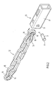
- Fig. 2 shows a three-dimensional exploded view of parts of a Chain lock, with one end of one when assembled Chain 12 fixed in a lock body 13 and another end of the Chain 12 in the lock body 13 by means of a locking mechanism, not shown can be locked.
- the chain 12 consists of a number of intertwined, essentially O-shaped chain links, in Fig. 2 for reasons only five chain links are shown for clarity. In a operational version of a chain lock, the chain 12 becomes a higher one Have number of chain links.
- the two end chain links 14 and 15 each have a two-sided Constriction 16, which are each perpendicular to the longitudinal direction the chain links 14, 15 extends.
- the lock body 13 consists of a housing 17 in the form of a square profile made of hardened steel.
- An opening is in shape in a side end portion of the housing 17 a circular recess 18 is provided which extends through both Side walls of the housing 17 extends through. 2 is only to see one side of the housing 17 and accordingly only one Recess 18.
- the diameter of the recess 18 is dimensioned so that it Diameter of a connecting pin 3 corresponds, which in Fig. 2 in a state after performing the cold forming riveting process according to the invention is shown.
- the connecting pin 3 Before the cold forming riveting process the connecting pin 3 has a constant diameter without an end face Thickenings 8, so that it easily through the recesses 16th can be put through. Only when performing the invention The cold-forming riveting process forms the thickenings 8 from which the connecting pin 3 is fixed in the recesses.
- Fig. 3 shows a sectional view of a lock area according to Fig. 2 and in particular that the chain link 14 by means of the invention in Housing 17 fixed connection pin 3 to the housing 17th connected is.
Landscapes
- Engineering & Computer Science (AREA)
- General Engineering & Computer Science (AREA)
- Manufacturing & Machinery (AREA)
- Mechanical Engineering (AREA)
- Insertion Pins And Rivets (AREA)
- Connection Of Plates (AREA)
Abstract
Description
Durch eine erfindungsgemäße Verbindungsvorrichtung wird die genannte Aufgabe dadurch gelöst, daß der Verbindungsstift aus Stahl mit einer Zugfestigkeit von mehr als 700 N/mm2 besteht, welcher mittels eines zumindest an seinen beiden stirnseitigen Enden erfolgten gefügeverdichtenden Kaltverformungs-Nietvorgangs in den Öffnungen fixiert ist.
- Fig. 1a bis 1f
- Schnittansichten von vier unterschiedlichen erfindungsgemäßen Verbindungsvorrichtungen,
- Fig. 2
- eine dreidimensionale Explosionszeichnung von Teilen eines Kettenschlosses mit einer erfindungsgemäßen Verbindungsvorrichtung, und
- Fig. 3
- eine Schnittansicht eines montierten Kettenschlosses gemäß Fig. 2.
Die Verdickung 6 stellt nach Abschluß des Kaltverformungs-Nietvorgangs sicher, daß die beiden Schloßbestandteile 1 auch nach Entfernen der Abstandshalter 5 den gewünschten Abstand zueinander aufweisen.
- 1
- stangenförmige Schloßbestandteile
- 2
- Öffnung
- 3
- Verbindungsstift
- 4
- Verdickung
- 5
- Abstandshalter
- 6
- Verdickung
- 7
- stangenförmige Schloßbestandteile bzw. Vierkant
- 7'
- stangenförmige Schloßbestandteile
- 8
- senkkopfartige Verdickung
- 9
- Verdickung
- 9'
- Verdickung
- 9"
- Verdickung
- 10
- Öffnung
- 10'
- Öffnung
- 11
- Schloßbestandteil
- 12
- Kette
- 13
- Schloßkörper
- 14
- Kettenglied
- 15
- Kettenglied
- 16
- Einschnürung
- 17
- Gehäuse
- 18
- Ausnehmung
- 19
- Durchgangsbereich
Claims (12)
- Verfahren zur Herstellung einer Verbindung zwischen zumindest zwei aus gehärtetem Material bestehenden Bereichen (1, 7, 11, 14, 17) eines Schlosses, wobei jeder der zu verbindenden Bereiche (1, 7, 11, 14, 17) jeweils eine Öffnung (2, 10, 10', 18, 19 ) aufweist, in denen ein Verbindungsstift (3) zur Kopplung der beiden Bereiche (1, 7, 11, 14, 17) fixiert wird,
dadurch gekennzeichnet, daß der aus Stahl mit einer Zugfestigkeit von mehr als 700 N/mm2 bestehende Verbindungsstift (3) in die Öffnungen (2, 10, 10', 18, 19) der bereits gehärteten Bereiche (1, 7, 11, 14, 17) eingeführt und anschließend dort mittels eines zumindest an seinen beiden stirnseitigen Enden erfolgenden gefügeverdichtenden Kaltverformungs-Nietvorgangs fixiert wird. - Verfahren nach Anspruch 1,
dadurch gekennzeichnet, daß ein Verbindungsstift (3) mit einer Zugfestigkeit von mehr als 800 N/mm2 verwendet wird. - Verfahren nach einem der vorhergehenden Ansprüche,
dadurch gekennzeichnet, daß ein Verbindungsstift (3) aus verschleißfestem Stahl, insbesondere aus Hartmanganstahl, vorzugsweise aus X120Mn12 verwendet wird. - Verfahren nach einem der vorhergehenden Ansprüche,
dadurch gekennzeichnet, daß während des Kaltverformungs-Nietvorgangs zwischen den beiden zu verbindenden Bereichen (1, 7, 11, 14, 17) ein Abstandshalter (5) angeordnet ist, oder
daß während des Kaltverformungs-Nietvorgangs die beiden zu verbindenden Bereiche (1) aneinander anliegen. - Verbindungsvorrichtung für zumindest zwei aus gehärtetem Material bestehende Bereiche (1, 7, 11, 14, 17) eines Schlosses, bei der jeder der zu verbindenden Bereiche (1, 7, 11, 14, 17) jeweils eine Öffnung (2, 10, 10', 18, 19) aufweist, in denen ein Verbindungsstift zur Kopplung der beiden Bereiche (1, 7, 11, 14, 17) fixiert ist,
dadurch gekennzeichnet, daß der Verbindungsstift (3) aus Stahl mit einer Zugfestigkeit von mehr als 700 N/mm2 besteht, welcher mittels eines zumindest an seinen beiden stirnseitigen Enden erfolgten gefügeverdichtenden Kaltverformungs-Nietvorgangs in den Öffnungen (2, 10, 10', 18, 19) fixiert ist. - Verbindungsvorrichtung nach Anspruch 5,
dadurch gekennzeichnet, daß die Zugfestigkeit des Verbindungsstifts (3) größer als 800 N/mm2 ist. - Verbindungsvorrichtung nach einem der Ansprüche 5 oder 6,
dadurch gekennzeichnet, daß der Verbindungsstift (3) aus verschleißfestem Stahl, insbesondere aus Hartmanganstahl, vorzugsweise aus X120Mn12 besteht. - Verbindungsvorrichtung nach einem der Ansprüche 5 bis 7,
dadurch gekennzeichnet, daß die beiden miteinander verbundenen Bereiche (1, 7, 11, 14, 17) entweder beabstandet zueinander oder aneinander angrenzend angeordnet sind. - Verbindungsvorrichtung nach einem der Ansprüche 5 bis 8,
dadurch gekennzeichnet, daß die beiden miteinander verbundenen Bereiche (7, 17) entweder Bestandteil eines einzigen Bauteils sind, oder
daß die beiden miteinander verbundenen Bereiche an verschiedenen Bauteilen (1, 7, 11) ausgebildet sind. - Schloß mit einer Verbindungsvorrichtung nach einem der Ansprüche 5 bis 9,
bei dem ein in einem Schloßkörper unlösbar zu fixierendes Schloßteil mittels der genannten Verbindungsvorrichtung mit dem Schloßkörper verbunden ist, oder
bei dem ein zumindest zwei Schloß-Gelenkstäbe (11) mittels der genannten Verbindungsvorrichtung miteinander verbunden sind. - Ketten-, Kabel- oder Gelenkschloß mit einem Schloßkörper (17) und einem langgestreckten Absperrelement in Form einer Kette (12), eines Kabels oder eines Gelenkstabs, welches bzw. welcher mit seinem ersten Ende (14) fest mit dem Schloßkörper (17) verbunden und mit seinem zweiten Ende (15) im Schloßkörper (17) mittels eines Schließmechanismus verriegelbar ist,
dadurch gekennzeichnet, daß das erste Ende eine Schlaufe (14) bildet, die einen Verbindungsstift (3) umgibt, der Bestandteil einer Verbindungsvorrichtung nach einem der Ansprüche 5 bis 9 ist, wobei die beiden mittels des Verbindungsstifts (3) verbundenen Bereiche jeweils Bereiche des Schloßkörpers (17) sind. - Ketten-, Kabel- oder Gelenkschloß nach Anspruch 11,
dadurch gekennzeichnet, daß die beiden mittels des Verbindungsstifts (3) verbundenen Bereiche des Schloßkörpers (17) einstückig miteinander ausgebildet sind und eine im wesentlichen vierkantförmige oder U-förmige Aufnahme für den Verbindungsstift (3) bilden.
Applications Claiming Priority (2)
| Application Number | Priority Date | Filing Date | Title |
|---|---|---|---|
| DE2001117925 DE10117925A1 (de) | 2001-04-10 | 2001-04-10 | Verbindungsvorrichtung und Verfahren zur Herstellung einer Verbindung |
| DE10117925 | 2001-04-10 |
Publications (3)
| Publication Number | Publication Date |
|---|---|
| EP1249566A2 true EP1249566A2 (de) | 2002-10-16 |
| EP1249566A3 EP1249566A3 (de) | 2004-01-07 |
| EP1249566B1 EP1249566B1 (de) | 2007-05-23 |
Family
ID=7681122
Family Applications (1)
| Application Number | Title | Priority Date | Filing Date |
|---|---|---|---|
| EP02006358A Expired - Lifetime EP1249566B1 (de) | 2001-04-10 | 2002-03-21 | Verfahren zur Herstellung einer Verbindung |
Country Status (2)
| Country | Link |
|---|---|
| EP (1) | EP1249566B1 (de) |
| DE (2) | DE10117925A1 (de) |
Cited By (1)
| Publication number | Priority date | Publication date | Assignee | Title |
|---|---|---|---|---|
| EP3925868A1 (de) * | 2020-06-18 | 2021-12-22 | ABUS August Bremicker Söhne KG | Halterung für ein tragbares schloss |
Family Cites Families (8)
| Publication number | Priority date | Publication date | Assignee | Title |
|---|---|---|---|---|
| US1845354A (en) * | 1927-09-29 | 1932-02-16 | Master Lock Co | Spare tire lock for automobiles |
| US3561102A (en) * | 1968-09-25 | 1971-02-09 | Champion Commercial Ind Inc | Process of forming a cold driven riveted joint |
| US3848389A (en) * | 1969-12-29 | 1974-11-19 | Textron Inc | Bimetal rivets |
| US4057982A (en) * | 1973-04-23 | 1977-11-15 | American Chain & Cable Company, Inc. | Theft-deterrent chain locking device |
| IT8204950U1 (it) * | 1982-06-18 | 1983-12-18 | Viro Innocenti Spa | Lucchetto perfezionato per catene. |
| US5732577A (en) * | 1993-08-11 | 1998-03-31 | Yamaha Hatsudoki Kabushiki Kaisha | Vehicle wheel lock |
| JP2935812B2 (ja) * | 1994-07-14 | 1999-08-16 | 三井金属鉱業株式会社 | 車両扉用ストライカー装置およびその製造方法 |
| IN188123B (de) * | 1995-04-20 | 2002-08-24 | Vi Goro Sarl |
-
2001
- 2001-04-10 DE DE2001117925 patent/DE10117925A1/de not_active Withdrawn
-
2002
- 2002-03-21 EP EP02006358A patent/EP1249566B1/de not_active Expired - Lifetime
- 2002-03-21 DE DE50210185T patent/DE50210185D1/de not_active Expired - Lifetime
Cited By (2)
| Publication number | Priority date | Publication date | Assignee | Title |
|---|---|---|---|---|
| EP3925868A1 (de) * | 2020-06-18 | 2021-12-22 | ABUS August Bremicker Söhne KG | Halterung für ein tragbares schloss |
| US12281499B2 (en) | 2020-06-18 | 2025-04-22 | ABUS August Bremicker Söhne KG | Holder for a portable lock |
Also Published As
| Publication number | Publication date |
|---|---|
| DE10117925A1 (de) | 2002-10-17 |
| EP1249566B1 (de) | 2007-05-23 |
| EP1249566A3 (de) | 2004-01-07 |
| DE50210185D1 (de) | 2007-07-05 |
Similar Documents
| Publication | Publication Date | Title |
|---|---|---|
| DE69102413T2 (de) | Förderkette. | |
| DE69207997T2 (de) | Lösbare Verbindungsvorrichtung für metallische Gerüstelemente | |
| WO2004018883A1 (de) | Verbindungseinrichtung | |
| AT389927B (de) | Kettenschloss fuer gliederketten | |
| CH671429A5 (de) | ||
| EP2090725A1 (de) | Steg zum Verbinden der beiden Zylinderhälften eines längenvariablen Doppelschliesszylinders | |
| DE19853712B4 (de) | Transport- und Verlegeanker mit querverstrebten Längsverankerungsschenkeln | |
| DE102016116429A1 (de) | Ultraschallschwingsystem mit Mantelflächenhalterung | |
| WO2022200421A1 (de) | Betätigungshandhabe | |
| DE2208509B2 (de) | Verbindungsglied | |
| DE20309265U1 (de) | Drehstangenverschluß für Türen, Klappen o.dgl. von Nutzfahrzeugaufbauten | |
| EP1249566B1 (de) | Verfahren zur Herstellung einer Verbindung | |
| EP4467841A1 (de) | Verbindungskettenglied zum verbinden von zumindest zwei kettengliedern einer kette | |
| EP1249568B1 (de) | Ketten- oder Kabelschloss | |
| EP0717204A1 (de) | Sicherheitsbolzen, der in Durchgangslöcher von Bauteilen bis zu einem Anschlag einschiebbar ist | |
| DE10355495A1 (de) | Zerlegbares Gerüst | |
| EP1321606B1 (de) | Profilzylinder | |
| DE3123128A1 (de) | Eckumlenkung fuer treibstangenbeschlaege | |
| EP0086381A2 (de) | Vorhängeschloss zur Verbindung zweier Glieder einer Kette | |
| DE102014100757A1 (de) | Tür- und/oder Fensterbeschlag-Befestigungsvorrichtung | |
| DE19546669C2 (de) | Verbindung zwischen einem Leiterholm und einem Gelenkschenkel eines Leitergelenkes | |
| DE4211796C2 (de) | Vorrichtung zum Verbinden und Verriegeln zweier Elemente | |
| DE202018102226U1 (de) | Endbefestigungsvorrichtung für ein Zugfederelement, sowie ein Zugfederelement mit einer Endbefestigungsvorrichtung | |
| DE3602284C1 (en) | Coupling element for the connection of round-link chains and their fittings | |
| DE4230476A1 (de) | Fenster- oder Türbeschlag |
Legal Events
| Date | Code | Title | Description |
|---|---|---|---|
| PUAI | Public reference made under article 153(3) epc to a published international application that has entered the european phase |
Free format text: ORIGINAL CODE: 0009012 |
|
| AK | Designated contracting states |
Kind code of ref document: A2 Designated state(s): AT BE CH CY DE DK ES FI FR GB GR IE IT LI LU MC NL PT SE TR |
|
| AX | Request for extension of the european patent |
Free format text: AL;LT;LV;MK;RO;SI |
|
| PUAL | Search report despatched |
Free format text: ORIGINAL CODE: 0009013 |
|
| AK | Designated contracting states |
Kind code of ref document: A3 Designated state(s): AT BE CH CY DE DK ES FI FR GB GR IE IT LI LU MC NL PT SE TR |
|
| AX | Request for extension of the european patent |
Extension state: AL LT LV MK RO SI |
|
| RIC1 | Information provided on ipc code assigned before grant |
Ipc: 7E 05B 71/00 B Ipc: 7E 05B 67/00 A |
|
| 17P | Request for examination filed |
Effective date: 20040707 |
|
| AKX | Designation fees paid |
Designated state(s): DE FR NL |
|
| 17Q | First examination report despatched |
Effective date: 20050125 |
|
| 17Q | First examination report despatched |
Effective date: 20050125 |
|
| GRAP | Despatch of communication of intention to grant a patent |
Free format text: ORIGINAL CODE: EPIDOSNIGR1 |
|
| RTI1 | Title (correction) |
Free format text: METHOD FOR CREATING A CONNECTION |
|
| GRAS | Grant fee paid |
Free format text: ORIGINAL CODE: EPIDOSNIGR3 |
|
| GRAA | (expected) grant |
Free format text: ORIGINAL CODE: 0009210 |
|
| AK | Designated contracting states |
Kind code of ref document: B1 Designated state(s): DE FR NL |
|
| REF | Corresponds to: |
Ref document number: 50210185 Country of ref document: DE Date of ref document: 20070705 Kind code of ref document: P |
|
| NLV1 | Nl: lapsed or annulled due to failure to fulfill the requirements of art. 29p and 29m of the patents act | ||
| ET | Fr: translation filed | ||
| PG25 | Lapsed in a contracting state [announced via postgrant information from national office to epo] |
Ref country code: NL Free format text: LAPSE BECAUSE OF FAILURE TO SUBMIT A TRANSLATION OF THE DESCRIPTION OR TO PAY THE FEE WITHIN THE PRESCRIBED TIME-LIMIT Effective date: 20070523 |
|
| PLBE | No opposition filed within time limit |
Free format text: ORIGINAL CODE: 0009261 |
|
| STAA | Information on the status of an ep patent application or granted ep patent |
Free format text: STATUS: NO OPPOSITION FILED WITHIN TIME LIMIT |
|
| 26N | No opposition filed |
Effective date: 20080226 |
|
| REG | Reference to a national code |
Ref country code: FR Ref legal event code: PLFP Year of fee payment: 15 |
|
| PGFP | Annual fee paid to national office [announced via postgrant information from national office to epo] |
Ref country code: FR Payment date: 20160321 Year of fee payment: 15 |
|
| PGFP | Annual fee paid to national office [announced via postgrant information from national office to epo] |
Ref country code: DE Payment date: 20160530 Year of fee payment: 15 |
|
| REG | Reference to a national code |
Ref country code: DE Ref legal event code: R119 Ref document number: 50210185 Country of ref document: DE |
|
| REG | Reference to a national code |
Ref country code: FR Ref legal event code: ST Effective date: 20171130 |
|
| PG25 | Lapsed in a contracting state [announced via postgrant information from national office to epo] |
Ref country code: FR Free format text: LAPSE BECAUSE OF NON-PAYMENT OF DUE FEES Effective date: 20170331 Ref country code: DE Free format text: LAPSE BECAUSE OF NON-PAYMENT OF DUE FEES Effective date: 20171003 |