EP1249332A1 - Vorrichtung zum Kühlen und Kalibrieren eines extrudierten Kunststoffprofils - Google Patents
Vorrichtung zum Kühlen und Kalibrieren eines extrudierten Kunststoffprofils Download PDFInfo
- Publication number
- EP1249332A1 EP1249332A1 EP02450050A EP02450050A EP1249332A1 EP 1249332 A1 EP1249332 A1 EP 1249332A1 EP 02450050 A EP02450050 A EP 02450050A EP 02450050 A EP02450050 A EP 02450050A EP 1249332 A1 EP1249332 A1 EP 1249332A1
- Authority
- EP
- European Patent Office
- Prior art keywords
- plastic profile
- damping
- calibration
- cooling
- profile
- Prior art date
- Legal status (The legal status is an assumption and is not a legal conclusion. Google has not performed a legal analysis and makes no representation as to the accuracy of the status listed.)
- Granted
Links
Images

Classifications
-
- B—PERFORMING OPERATIONS; TRANSPORTING
- B29—WORKING OF PLASTICS; WORKING OF SUBSTANCES IN A PLASTIC STATE IN GENERAL
- B29C—SHAPING OR JOINING OF PLASTICS; SHAPING OF MATERIAL IN A PLASTIC STATE, NOT OTHERWISE PROVIDED FOR; AFTER-TREATMENT OF THE SHAPED PRODUCTS, e.g. REPAIRING
- B29C48/00—Extrusion moulding, i.e. expressing the moulding material through a die or nozzle which imparts the desired form; Apparatus therefor
- B29C48/25—Component parts, details or accessories; Auxiliary operations
- B29C48/88—Thermal treatment of the stream of extruded material, e.g. cooling
- B29C48/90—Thermal treatment of the stream of extruded material, e.g. cooling with calibration or sizing, i.e. combined with fixing or setting of the final dimensions of the extruded article
- B29C48/901—Thermal treatment of the stream of extruded material, e.g. cooling with calibration or sizing, i.e. combined with fixing or setting of the final dimensions of the extruded article of hollow bodies
- B29C48/903—Thermal treatment of the stream of extruded material, e.g. cooling with calibration or sizing, i.e. combined with fixing or setting of the final dimensions of the extruded article of hollow bodies externally
-
- B—PERFORMING OPERATIONS; TRANSPORTING
- B29—WORKING OF PLASTICS; WORKING OF SUBSTANCES IN A PLASTIC STATE IN GENERAL
- B29C—SHAPING OR JOINING OF PLASTICS; SHAPING OF MATERIAL IN A PLASTIC STATE, NOT OTHERWISE PROVIDED FOR; AFTER-TREATMENT OF THE SHAPED PRODUCTS, e.g. REPAIRING
- B29C48/00—Extrusion moulding, i.e. expressing the moulding material through a die or nozzle which imparts the desired form; Apparatus therefor
- B29C48/03—Extrusion moulding, i.e. expressing the moulding material through a die or nozzle which imparts the desired form; Apparatus therefor characterised by the shape of the extruded material at extrusion
- B29C48/09—Articles with cross-sections having partially or fully enclosed cavities, e.g. pipes or channels
-
- B—PERFORMING OPERATIONS; TRANSPORTING
- B29—WORKING OF PLASTICS; WORKING OF SUBSTANCES IN A PLASTIC STATE IN GENERAL
- B29C—SHAPING OR JOINING OF PLASTICS; SHAPING OF MATERIAL IN A PLASTIC STATE, NOT OTHERWISE PROVIDED FOR; AFTER-TREATMENT OF THE SHAPED PRODUCTS, e.g. REPAIRING
- B29C48/00—Extrusion moulding, i.e. expressing the moulding material through a die or nozzle which imparts the desired form; Apparatus therefor
- B29C48/03—Extrusion moulding, i.e. expressing the moulding material through a die or nozzle which imparts the desired form; Apparatus therefor characterised by the shape of the extruded material at extrusion
- B29C48/12—Articles with an irregular circumference when viewed in cross-section, e.g. window profiles
-
- B—PERFORMING OPERATIONS; TRANSPORTING
- B29—WORKING OF PLASTICS; WORKING OF SUBSTANCES IN A PLASTIC STATE IN GENERAL
- B29C—SHAPING OR JOINING OF PLASTICS; SHAPING OF MATERIAL IN A PLASTIC STATE, NOT OTHERWISE PROVIDED FOR; AFTER-TREATMENT OF THE SHAPED PRODUCTS, e.g. REPAIRING
- B29C48/00—Extrusion moulding, i.e. expressing the moulding material through a die or nozzle which imparts the desired form; Apparatus therefor
- B29C48/25—Component parts, details or accessories; Auxiliary operations
- B29C48/88—Thermal treatment of the stream of extruded material, e.g. cooling
- B29C48/90—Thermal treatment of the stream of extruded material, e.g. cooling with calibration or sizing, i.e. combined with fixing or setting of the final dimensions of the extruded article
- B29C48/908—Thermal treatment of the stream of extruded material, e.g. cooling with calibration or sizing, i.e. combined with fixing or setting of the final dimensions of the extruded article characterised by calibrator surface, e.g. structure or holes for lubrication, cooling or venting
-
- B—PERFORMING OPERATIONS; TRANSPORTING
- B29—WORKING OF PLASTICS; WORKING OF SUBSTANCES IN A PLASTIC STATE IN GENERAL
- B29C—SHAPING OR JOINING OF PLASTICS; SHAPING OF MATERIAL IN A PLASTIC STATE, NOT OTHERWISE PROVIDED FOR; AFTER-TREATMENT OF THE SHAPED PRODUCTS, e.g. REPAIRING
- B29C48/00—Extrusion moulding, i.e. expressing the moulding material through a die or nozzle which imparts the desired form; Apparatus therefor
- B29C48/25—Component parts, details or accessories; Auxiliary operations
- B29C48/88—Thermal treatment of the stream of extruded material, e.g. cooling
- B29C48/911—Cooling
- B29C48/9115—Cooling of hollow articles
- B29C48/912—Cooling of hollow articles of tubular films
- B29C48/913—Cooling of hollow articles of tubular films externally
-
- B—PERFORMING OPERATIONS; TRANSPORTING
- B29—WORKING OF PLASTICS; WORKING OF SUBSTANCES IN A PLASTIC STATE IN GENERAL
- B29C—SHAPING OR JOINING OF PLASTICS; SHAPING OF MATERIAL IN A PLASTIC STATE, NOT OTHERWISE PROVIDED FOR; AFTER-TREATMENT OF THE SHAPED PRODUCTS, e.g. REPAIRING
- B29C48/00—Extrusion moulding, i.e. expressing the moulding material through a die or nozzle which imparts the desired form; Apparatus therefor
- B29C48/25—Component parts, details or accessories; Auxiliary operations
- B29C48/88—Thermal treatment of the stream of extruded material, e.g. cooling
- B29C48/919—Thermal treatment of the stream of extruded material, e.g. cooling using a bath, e.g. extruding into an open bath to coagulate or cool the material
-
- B—PERFORMING OPERATIONS; TRANSPORTING
- B29—WORKING OF PLASTICS; WORKING OF SUBSTANCES IN A PLASTIC STATE IN GENERAL
- B29L—INDEXING SCHEME ASSOCIATED WITH SUBCLASS B29C, RELATING TO PARTICULAR ARTICLES
- B29L2031/00—Other particular articles
- B29L2031/001—Profiled members, e.g. beams, sections
- B29L2031/003—Profiled members, e.g. beams, sections having a profiled transverse cross-section
Definitions
- the invention relates to a device for cooling and calibration an extruded plastic profile with a coolant Cooling tank, with calibration panels arranged inside the cooling tank for the plastic profile exposed to the coolant and with a Cooling tank downstream in the pull-off direction of the plastic profile.
- the shape is given Profile die emerging, hot profile strand calibrated and cooled, whereby for Cooling a cooling tank is provided through which the plastic profile with With the help of an extraction device downstream of the cooling tank.
- a cooling tank Inside the cooling tank, the plastic profile with a cooling liquid, in general water, sprayed or drawn through a coolant bath.
- a cooling liquid in general water, sprayed or drawn through a coolant bath.
- the dimensional accuracy of the calibration orifices drawn plastic profile ensured. Because of not clearly clarified Circumstances can lead to markings associated with profile vibrations come on the plastic profile, which is transverse to the deduction direction of the Plastic profile run and especially through differences in gloss in the Make surface area noticeable.
- the invention is therefore based on the object of a device for Cooling and calibrating an extruded plastic profile of the one described above Kind so that such occasional markings can be suppressed.
- the invention solves the problem in that between the at least inlet-side calibration panel of the cooling tank and the extraction device one at least in sections in the area of a circumference on the plastic profile adjacent damping device is provided.
- the invention is based on the knowledge that the fine, mainly Markings appearing on the outer surfaces of the plastic profile in contrast to "chatter marks" not of unfavorable friction conditions depend between the calibration panels and the plastic profile, but of a vibration excitation of between the trigger device and the Calibration screens similar to a string of clamped plastic profiles.
- This possibly also vibrations excited by resonance phenomena, essentially longitudinal vibrations, the plastic profile in the area between those through the trigger device and the calibration orifices Clamping points formed can at least be damped dampen to an extent that surface markings on the plastic profile excludes.
- the damping device must at least in sections lie in the area of a circumference on the plastic profile, so that such vibrations of the plastic profile can be suppressed.
- the cheapest Damping properties can then be used for a damping device can be used if they are in the area of the greatest vibration range, i.e. in the is provided essentially centrally between nodes.
- the damping devices can be designed very differently be because it is only a suppression of the longitudinal vibrations of the Plastic profile goes. Should be a damping device within the cooling tank are provided, under certain circumstances by the damping device possible deformation of the plastic profile. To the Ensuring the required dimensional accuracy of the plastic profile can be done in one In such a case, the damping device consists of two immediately successive Calibration panels offset against each other across the plastic profile exist that counteract an impermissible deformation of the plastic profile. However, these calibration orifices can also be offset by one Longitudinal axis of the plastic profile are rotated to a vibration of the To achieve plastic profile suppressing profile guidance. The pair of calibration orifices A damping device can of course also be sent to the Instead of a calibration orifice to be provided.
- the damping device is independent of a precise setting at least one of the calibration panels can fit snugly against the plastic profile the damping device in the direction of its displacement compared to the other calibration orifice are spring loaded. Through such resilient The damping device can also be subjected to calibration orifices any wear that may occur can easily be compensated for.
- damping rollers which also have a possible longitudinal vibration suppress the plastic profile, especially if these damping rollers lie on the plastic profile with a rubber-elastic running layer.
- Damping rollers are mainly between the trigger and the Cooling tank are used, i.e. in an area where the plastic profile already has sufficient inherent strength.
- the damping rollers can in turn be resilient to the Plastic profile can be pressed.
- Damping devices are usually rigid on their supports arranged. Under certain circumstances, however, the damping devices can be advantageous to be supported by spring bodies on their supports, so that, for example a changed natural vibration behavior of plastic profiles and damping device with the effect that marks on Suppresses the resonance vibrations of the plastic profile become.
- Fig. 1 this is from a profile nozzle 1 emerging from an extruder, hot plastic profile 2 through a calibration device 3 is drawn before it passes through a cooling tank 4, in the calibration orifices 5 arranged at a distance from one another are to ensure the dimensional accuracy of the plastic profile 2 even when cooling.
- the calibration screens 5 must therefore be designed so that the cooling-related shrinkage of the plastic profile 2 is taken into account becomes.
- the cooling liquid used to cool the plastic profile 2 usually Water can be sprayed onto the plastic profile 2.
- easier Design relationships arise, however, when the plastic profile 2 is drawn through a cooling liquid bath 6 in the cooling tank 4.
- the plastic profile 2 from the cooling tank 4 is used for an extraction device 7, which the plastic profile 2 in a conventional manner with the help of rotating Caterpillars 8 recorded.
- damping devices 9 are used as needed, the the possible vibrations at least to a permissible size reduce.
- damping devices are therefore preferably in Area between the cooling tank 4 and the extraction device 7, but also in the Cooling tank 4, preferably provided in the outlet-side third.
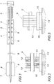
- the calibration orifices 10 and 11 from opposite sides to the plastic profile 2 are 10 and 11 longitudinal vibrations through this pair of calibration orifices of the plastic profile 2 are effectively suppressed.
- To compensate for Tolerances and signs of wear can be at least one of the two Calibration diaphragms 10, 11 by a spring 12 in the direction of the mutual Displacement of the two calibration orifices 10 and 11 can be resiliently applied.
- the damping device 9 according to FIG. 3 differs from 2 only in that the two calibration apertures 10 and 11 receiving housings 13 are not rigidly connected to a carrier 14 is, but supported against this carrier 14 by spring body 15 is so that the damping device 9 part of the plastic profile by the 1st certain vibration system, with the result that the Natural vibrations of the vibration system shift, which leads to a sufficient Reduction of the occurrence of marks on the plastic profile 1 can lead to significant vibration amplitudes.
- the damping device 9 according to FIG. 4 also uses a Pair of calibration orifices, but the calibration orifices 10, 11 are against each other pivoted about a longitudinal axis of the plastic profile 2.
- the plastic profile 2 is clamped positively between these calibration orifices 10 and 11 again, what the intended suppression of longitudinal vibrations of the Plastic profile 2 results in the dimensional accuracy of the plastic profile without one 2 dangerous deformation of the plastic profile 2.
- the damping device 9 consists of one of the Cooling tank 4 provided calibration panels 5, to which on the plastic profile 2 adjacent damping body 16 are attached.
- This damping body 16 consist preferably of a different from the calibration aperture 5 Material to face different friction conditions to achieve the plastic profile 2, whereby the desired vibration damping is supported.
- the damping bodies 16 can in turn at least one pressed against the plastic profile 2 by a spring 12 become.
- FIG. 6 shows a damping device 9, which consists of two the plastic profile 2 exists between leading damping rollers 17, which on the longitudinal vibrations of the plastic profile 2 to torsional vibrations be stimulated. Due to the different natural frequency of the damping rollers 17 results in an effective damping of the wings of the plastic profile 2.
- the damping rollers 17 are for better vibration damping provided with a rubber-elastic running layer 18, via which they on the Plastic profile 2 act, with a braking force on the damping rollers 17 can have an advantageous effect on vibration damping.
Abstract
Description
- Fig. 1
- eine erfindungsgemäße Vorrichtung zum Kalibrieren und Kühlen eines extrudierten Kunststoffprofils in einem schematischen Längsschnitt,
- Fig. 2
- eine erfindungsgemäße Dämpfungseinrichtung in einem Schnitt durch eine Längsachse des Kunststoffprofils in einem größeren Maßstab,
- Fig. 3
- die Dämpfungseinrichtung nach der Fig. 2 in einer Seitenansicht, jedoch mit einer federnden Abstützung gegenüber einem Träger,
- Fig. 4
- eine Konstruktionsvariante einer erfindungsgemäßen Dämpfungseinrichtung in einer Ansicht in Längsrichtung des Kunststoffprofils,
- Fig. 5
- eine weitere Ausführungsform einer erfindungsgemäßen Dämpfungseinrichtung in einem Schnitt durch eine Längsachse des Kunststoffprofils und
- Fig. 6
- eine weitere abgewandelte Ausführungsform einer erfindungsgemäßen Dämpfungseinrichtung in einem Schnitt entlang einer Längsachse des Kunststoffprofils.
Claims (11)
- Vorrichtung zum Kühlen und Kalibrieren eines extrudierten Kunststoffprofils (2) mit einem eine Kühlflüssigkeit aufnehmenden Kühltank (4), mit innerhalb des Kühltanks (4) angeordneten Kalibrierblenden (5) für das der Kühlflüssigkeit ausgesetzte Kunststoffprofil (2) und mit einer dem Kühltank (4) in Abzugsrichtung des Kunststoffprofils (2) nachgeordneten Abzugseinrichtung (7), dadurch gekennzeichnet, daß zwischen der zulaufseitigen Kalibrierblende (5) des Kühltanks (4) und der Abzugseinrichtung (7) wenigstens eine zumindest abschnittsweise im Bereich eines Umfangs am Kunststoffprofil (2) anliegende Dämpfungseinrichtung (9) vorgesehen ist.
- Vorrichtung nach Anspruch 1, dadurch gekennzeichnet, daß die Dämpfungseinrichtung (9) aus zwei unmittelbar aufeinanderfolgenden, gegeneinander quer zum Kunststoffprofil (2) versetzten Kalibrierblenden (10, 11) besteht.
- Vorrichtung nach Anspruch 1, dadurch gekennzeichnet, daß die Dämpfungseinrichtung (9) aus zwei unmittelbar aufeinanderfolgenden, gegeneinander um eine Längsachse des Kunststoffprofils (2) winkelversetzten Kalibrierblenden (10, 11) besteht.
- Vorrichtung nach Anspruch 2 oder 3, dadurch gekennzeichnet, daß zumindest eine der Kalibrierblenden (10, 11) der Dämpfungseinrichtung (9) in Richtung ihrer Versetzung gegenüber der anderen Kalibrierblende (10, 11) federnd beaufschlagbar ist.
- Vorrichtung nach Anspruch 1, dadurch gekennzeichnet, daß die Dämpfungseinrichtung (9) aus zwei das Kunststoffprofil (2) zwischen sich führenden Dämpfungsrollen (17) besteht.
- Vorrichtung nach Anspruch 5, dadurch gekennzeichnet, daß die Dämpfungsrollen (17) mit einer gummielastischen Laufschicht (18) am Kunststoffprofil (2) anliegen.
- Vorrichtung nach Anspruch 6 oder 7, dadurch gekennzeichnet, daß die Dämpfungsrollen (17) federnd an das Kunststoffprofil (2) andrückbar sind.
- Vorrichtung nach Anspruch 1, dadurch gekennzeichnet, daß die Dämpfungseinrichtung (9) aus einer Kalibrierblende (5) besteht, an die am Kunststoffprofil (2) anliegende Dämpfungskörper (16) angesetzt sind.
- Vorrichtung nach Anspruch 8, dadurch gekennzeichnet, daß die Dämpfungskörper (16) zumindest im Bereich der Anlage am Kunststoffprofil (2) aus einem von der zugehörigen Kalibrierblende (5) unterschiedlichen Werkstoff bestehen.
- Vorrichtung nach Anspruch 8 oder 9, dadurch gekennzeichnet, daß die Dämpfungskörper (16) federnd an das Kunststoffprofil (2) andrückbar sind.
- Vorrichtung nach einem der Ansprüche 1 bis 10, dadurch gekennzeichnet, daß die Dämpfungseinrichtung (9) über Federkörper (15) auf einem Träger (14) abgestützt ist.
Priority Applications (1)
| Application Number | Priority Date | Filing Date | Title |
|---|---|---|---|
| AT02450050T ATE322968T1 (de) | 2001-04-09 | 2002-03-08 | Vorrichtung zum kühlen und kalibrieren eines extrudierten kunststoffprofils |
Applications Claiming Priority (2)
| Application Number | Priority Date | Filing Date | Title |
|---|---|---|---|
| AT0056501A AT409736B (de) | 2001-04-09 | 2001-04-09 | Vorrichtung zum kühlen und kalibrieren eines extrudierten kunststoffprofils |
| AT2001565 | 2001-04-09 |
Publications (2)
| Publication Number | Publication Date |
|---|---|
| EP1249332A1 true EP1249332A1 (de) | 2002-10-16 |
| EP1249332B1 EP1249332B1 (de) | 2006-04-12 |
Family
ID=3676662
Family Applications (1)
| Application Number | Title | Priority Date | Filing Date |
|---|---|---|---|
| EP02450050A Expired - Lifetime EP1249332B1 (de) | 2001-04-09 | 2002-03-08 | Vorrichtung zum Kühlen und Kalibrieren eines extrudierten Kunststoffprofils |
Country Status (4)
| Country | Link |
|---|---|
| US (1) | US6840748B2 (de) |
| EP (1) | EP1249332B1 (de) |
| AT (2) | AT409736B (de) |
| DE (1) | DE50206352D1 (de) |
Cited By (3)
| Publication number | Priority date | Publication date | Assignee | Title |
|---|---|---|---|---|
| WO2006096898A2 (de) * | 2005-03-16 | 2006-09-21 | Greiner Extrusionstechnik Gmbh | Traganordnung für ein extrusionswerkzeug sowie extrusionswerkzeug zur formgebung eines gegenstandes |
| WO2012069642A3 (de) * | 2010-11-25 | 2012-10-26 | Greiner Tool.Tec Gmbh | Vorrichtung und verfahren zur gezielten verformung eines extrudierten kunststoffprofils |
| US10392812B2 (en) | 2012-08-09 | 2019-08-27 | Ceraloc Innovation Ab | Single layer scattering of powder surfaces |
Families Citing this family (1)
| Publication number | Priority date | Publication date | Assignee | Title |
|---|---|---|---|---|
| AT523885A1 (de) * | 2020-05-25 | 2021-12-15 |
Citations (6)
| Publication number | Priority date | Publication date | Assignee | Title |
|---|---|---|---|---|
| US2423260A (en) * | 1944-12-29 | 1947-07-01 | Extruded Plasties Inc | Extrusion of tubing |
| US2903743A (en) * | 1954-01-18 | 1959-09-15 | Lysobey John | Manufacture of flexible-walled tubing |
| DE1157378B (de) * | 1959-05-06 | 1963-11-14 | Frieseke & Hoepfner Gmbh | Extruder-Anlage zum Herstellen von Hohlprofilen aus thermoplastischem Material |
| DE1201038B (de) * | 1960-05-19 | 1965-09-16 | Kloeckner Werke Ag | Vakuum-Kalibriervorrichtung fuer Hohlprofile aus Kunststoff |
| DE1504364A1 (de) * | 1964-12-31 | 1969-04-10 | Rheinstahl Henschel Ag | Einrichtung zum Blasen von Folien in horizontaler Arbeitsweise |
| US3958913A (en) * | 1973-12-01 | 1976-05-25 | Hoechst Aktiengesellschaft | Cooling device for tubular sheeting |
Family Cites Families (1)
| Publication number | Priority date | Publication date | Assignee | Title |
|---|---|---|---|---|
| US3552259A (en) * | 1968-07-19 | 1971-01-05 | Commerican Solvents Corp | Process and apparatus for preparing detonating and deflagrating fuse and product |
-
2001
- 2001-04-09 AT AT0056501A patent/AT409736B/de not_active IP Right Cessation
-
2002
- 2002-03-08 EP EP02450050A patent/EP1249332B1/de not_active Expired - Lifetime
- 2002-03-08 DE DE50206352T patent/DE50206352D1/de not_active Expired - Fee Related
- 2002-03-08 AT AT02450050T patent/ATE322968T1/de not_active IP Right Cessation
- 2002-04-08 US US10/118,408 patent/US6840748B2/en not_active Expired - Fee Related
Patent Citations (6)
| Publication number | Priority date | Publication date | Assignee | Title |
|---|---|---|---|---|
| US2423260A (en) * | 1944-12-29 | 1947-07-01 | Extruded Plasties Inc | Extrusion of tubing |
| US2903743A (en) * | 1954-01-18 | 1959-09-15 | Lysobey John | Manufacture of flexible-walled tubing |
| DE1157378B (de) * | 1959-05-06 | 1963-11-14 | Frieseke & Hoepfner Gmbh | Extruder-Anlage zum Herstellen von Hohlprofilen aus thermoplastischem Material |
| DE1201038B (de) * | 1960-05-19 | 1965-09-16 | Kloeckner Werke Ag | Vakuum-Kalibriervorrichtung fuer Hohlprofile aus Kunststoff |
| DE1504364A1 (de) * | 1964-12-31 | 1969-04-10 | Rheinstahl Henschel Ag | Einrichtung zum Blasen von Folien in horizontaler Arbeitsweise |
| US3958913A (en) * | 1973-12-01 | 1976-05-25 | Hoechst Aktiengesellschaft | Cooling device for tubular sheeting |
Cited By (5)
| Publication number | Priority date | Publication date | Assignee | Title |
|---|---|---|---|---|
| WO2006096898A2 (de) * | 2005-03-16 | 2006-09-21 | Greiner Extrusionstechnik Gmbh | Traganordnung für ein extrusionswerkzeug sowie extrusionswerkzeug zur formgebung eines gegenstandes |
| WO2006096898A3 (de) * | 2005-03-16 | 2007-04-12 | Greiner Extrusionstechnik Gmbh | Traganordnung für ein extrusionswerkzeug sowie extrusionswerkzeug zur formgebung eines gegenstandes |
| US7878792B2 (en) | 2005-03-16 | 2011-02-01 | Greiner Tool. Tec Gmbh | Support arrangement for an extrusion tool and extrusion tool for moulding an object |
| WO2012069642A3 (de) * | 2010-11-25 | 2012-10-26 | Greiner Tool.Tec Gmbh | Vorrichtung und verfahren zur gezielten verformung eines extrudierten kunststoffprofils |
| US10392812B2 (en) | 2012-08-09 | 2019-08-27 | Ceraloc Innovation Ab | Single layer scattering of powder surfaces |
Also Published As
| Publication number | Publication date |
|---|---|
| DE50206352D1 (de) | 2006-05-24 |
| US20020146477A1 (en) | 2002-10-10 |
| AT409736B (de) | 2002-10-25 |
| EP1249332B1 (de) | 2006-04-12 |
| US6840748B2 (en) | 2005-01-11 |
| ATE322968T1 (de) | 2006-04-15 |
| ATA5652001A (de) | 2002-03-15 |
Similar Documents
| Publication | Publication Date | Title |
|---|---|---|
| DE2921050C2 (de) | ||
| DE19645030B4 (de) | Schwingungsdämpfendes Verbundbauteil und Herstellungsverfahren | |
| DE602005003887T2 (de) | Vorrichtung und Verfahren zum Befestigen einer linearen Skala | |
| DE2521363C2 (de) | Hubschrauber-Rotorblatt | |
| DE2502619B2 (de) | Bausatz zum Aufbau eines zur Aufnahme von Instrumenten, insbesondere Laborinstrumenten, bestimmten Gestells | |
| DE4319886C1 (de) | Anordnung zum Kompensieren temperaturabhängiger Volumenänderungen eines Hohlleiters | |
| DE2627450A1 (de) | Flaechiges hohlprofil insbesondere zur verwendung als bewegter teil einer textilmaschine | |
| EP1249332A1 (de) | Vorrichtung zum Kühlen und Kalibrieren eines extrudierten Kunststoffprofils | |
| EP0009573A1 (de) | Transportwalze für ein Gerät zur Nassbehandlung fotografischer Schichtträger und Verfahren zur Herstellung einer solchen Walze | |
| DE2607822B2 (de) | Stoffauflauf für Papiermaschinen | |
| DE102012101614A1 (de) | Vorrichtung zum Verschließen eines Gehäuses eines Steckverbinders | |
| DE2650944A1 (de) | Zusammengesetzter profilstab fuer fenster- und fassadenkonstruktionen | |
| DE2933726A1 (de) | Schwingungsdaempfer | |
| DE10014808A1 (de) | Gummilager mit abgestuftem Dämpfungsverhalten | |
| EP0280107A1 (de) | Wasser/Luft-Kühler | |
| EP2518345B1 (de) | Abdeckung zur aufnahme eines profilschienenwagens eines linearlagers | |
| DE3709507A1 (de) | Spitzenschutzvorrichtung an einer spruehpistole | |
| DE2942847A1 (de) | Magnetfelddifferenzsonde | |
| DE2539363C2 (de) | Blendrahmenschenkel | |
| EP1619364B1 (de) | Schwingungsisolator | |
| DE3614878A1 (de) | Gaslaser | |
| DE3818672C2 (de) | ||
| DE2756994A1 (de) | Stuetzvorrichtung fuer ein siebband | |
| DE3119499C2 (de) | Körperschalldämpfer | |
| DE102018114049B4 (de) | Ölwannenbaugruppe |
Legal Events
| Date | Code | Title | Description |
|---|---|---|---|
| PUAI | Public reference made under article 153(3) epc to a published international application that has entered the european phase |
Free format text: ORIGINAL CODE: 0009012 |
|
| AK | Designated contracting states |
Kind code of ref document: A1 Designated state(s): AT BE CH CY DE DK ES FI FR GB GR IE IT LI LU MC NL PT SE TR |
|
| AX | Request for extension of the european patent |
Free format text: AL;LT;LV;MK;RO;SI |
|
| 17P | Request for examination filed |
Effective date: 20021118 |
|
| AKX | Designation fees paid |
Designated state(s): AT BE CH CY DE DK ES FI FR GB GR IE IT LI LU MC NL PT SE TR |
|
| 17Q | First examination report despatched |
Effective date: 20030619 |
|
| GRAP | Despatch of communication of intention to grant a patent |
Free format text: ORIGINAL CODE: EPIDOSNIGR1 |
|
| GRAS | Grant fee paid |
Free format text: ORIGINAL CODE: EPIDOSNIGR3 |
|
| GRAA | (expected) grant |
Free format text: ORIGINAL CODE: 0009210 |
|
| AK | Designated contracting states |
Kind code of ref document: B1 Designated state(s): AT BE CH CY DE DK ES FI FR GB GR IE IT LI LU MC NL PT SE TR |
|
| PG25 | Lapsed in a contracting state [announced via postgrant information from national office to epo] |
Ref country code: IT Free format text: LAPSE BECAUSE OF FAILURE TO SUBMIT A TRANSLATION OF THE DESCRIPTION OR TO PAY THE FEE WITHIN THE PRESCRIBED TIME-LIMIT;WARNING: LAPSES OF ITALIAN PATENTS WITH EFFECTIVE DATE BEFORE 2007 MAY HAVE OCCURRED AT ANY TIME BEFORE 2007. THE CORRECT EFFECTIVE DATE MAY BE DIFFERENT FROM THE ONE RECORDED. Effective date: 20060412 Ref country code: NL Free format text: LAPSE BECAUSE OF FAILURE TO SUBMIT A TRANSLATION OF THE DESCRIPTION OR TO PAY THE FEE WITHIN THE PRESCRIBED TIME-LIMIT Effective date: 20060412 Ref country code: IE Free format text: LAPSE BECAUSE OF FAILURE TO SUBMIT A TRANSLATION OF THE DESCRIPTION OR TO PAY THE FEE WITHIN THE PRESCRIBED TIME-LIMIT Effective date: 20060412 Ref country code: FI Free format text: LAPSE BECAUSE OF FAILURE TO SUBMIT A TRANSLATION OF THE DESCRIPTION OR TO PAY THE FEE WITHIN THE PRESCRIBED TIME-LIMIT Effective date: 20060412 |
|
| REG | Reference to a national code |
Ref country code: GB Ref legal event code: FG4D Free format text: NOT ENGLISH |
|
| REG | Reference to a national code |
Ref country code: CH Ref legal event code: EP |
|
| REF | Corresponds to: |
Ref document number: 50206352 Country of ref document: DE Date of ref document: 20060524 Kind code of ref document: P |
|
| REG | Reference to a national code |
Ref country code: IE Ref legal event code: FG4D Free format text: LANGUAGE OF EP DOCUMENT: GERMAN |
|
| PG25 | Lapsed in a contracting state [announced via postgrant information from national office to epo] |
Ref country code: DK Free format text: LAPSE BECAUSE OF FAILURE TO SUBMIT A TRANSLATION OF THE DESCRIPTION OR TO PAY THE FEE WITHIN THE PRESCRIBED TIME-LIMIT Effective date: 20060712 Ref country code: SE Free format text: LAPSE BECAUSE OF FAILURE TO SUBMIT A TRANSLATION OF THE DESCRIPTION OR TO PAY THE FEE WITHIN THE PRESCRIBED TIME-LIMIT Effective date: 20060712 |
|
| PG25 | Lapsed in a contracting state [announced via postgrant information from national office to epo] |
Ref country code: ES Free format text: LAPSE BECAUSE OF FAILURE TO SUBMIT A TRANSLATION OF THE DESCRIPTION OR TO PAY THE FEE WITHIN THE PRESCRIBED TIME-LIMIT Effective date: 20060723 |
|
| GBT | Gb: translation of ep patent filed (gb section 77(6)(a)/1977) |
Effective date: 20060705 |
|
| PG25 | Lapsed in a contracting state [announced via postgrant information from national office to epo] |
Ref country code: PT Free format text: LAPSE BECAUSE OF FAILURE TO SUBMIT A TRANSLATION OF THE DESCRIPTION OR TO PAY THE FEE WITHIN THE PRESCRIBED TIME-LIMIT Effective date: 20060912 |
|
| NLV1 | Nl: lapsed or annulled due to failure to fulfill the requirements of art. 29p and 29m of the patents act | ||
| REG | Reference to a national code |
Ref country code: IE Ref legal event code: FD4D |
|
| ET | Fr: translation filed | ||
| PLBE | No opposition filed within time limit |
Free format text: ORIGINAL CODE: 0009261 |
|
| STAA | Information on the status of an ep patent application or granted ep patent |
Free format text: STATUS: NO OPPOSITION FILED WITHIN TIME LIMIT |
|
| 26N | No opposition filed |
Effective date: 20070115 |
|
| REG | Reference to a national code |
Ref country code: CH Ref legal event code: PL |
|
| PG25 | Lapsed in a contracting state [announced via postgrant information from national office to epo] |
Ref country code: MC Free format text: LAPSE BECAUSE OF NON-PAYMENT OF DUE FEES Effective date: 20070331 |
|
| PG25 | Lapsed in a contracting state [announced via postgrant information from national office to epo] |
Ref country code: CH Free format text: LAPSE BECAUSE OF NON-PAYMENT OF DUE FEES Effective date: 20070331 Ref country code: LI Free format text: LAPSE BECAUSE OF NON-PAYMENT OF DUE FEES Effective date: 20070331 |
|
| PG25 | Lapsed in a contracting state [announced via postgrant information from national office to epo] |
Ref country code: GR Free format text: LAPSE BECAUSE OF FAILURE TO SUBMIT A TRANSLATION OF THE DESCRIPTION OR TO PAY THE FEE WITHIN THE PRESCRIBED TIME-LIMIT Effective date: 20060713 |
|
| PGFP | Annual fee paid to national office [announced via postgrant information from national office to epo] |
Ref country code: GB Payment date: 20080327 Year of fee payment: 7 |
|
| PG25 | Lapsed in a contracting state [announced via postgrant information from national office to epo] |
Ref country code: AT Free format text: LAPSE BECAUSE OF NON-PAYMENT OF DUE FEES Effective date: 20070308 |
|
| PGFP | Annual fee paid to national office [announced via postgrant information from national office to epo] |
Ref country code: DE Payment date: 20080422 Year of fee payment: 7 |
|
| PGFP | Annual fee paid to national office [announced via postgrant information from national office to epo] |
Ref country code: BE Payment date: 20080416 Year of fee payment: 7 Ref country code: TR Payment date: 20080305 Year of fee payment: 7 Ref country code: IT Payment date: 20080328 Year of fee payment: 7 |
|
| PGFP | Annual fee paid to national office [announced via postgrant information from national office to epo] |
Ref country code: FR Payment date: 20080319 Year of fee payment: 7 |
|
| PG25 | Lapsed in a contracting state [announced via postgrant information from national office to epo] |
Ref country code: CY Free format text: LAPSE BECAUSE OF FAILURE TO SUBMIT A TRANSLATION OF THE DESCRIPTION OR TO PAY THE FEE WITHIN THE PRESCRIBED TIME-LIMIT Effective date: 20060412 Ref country code: LU Free format text: LAPSE BECAUSE OF NON-PAYMENT OF DUE FEES Effective date: 20070308 |
|
| BERE | Be: lapsed |
Owner name: *A + G EXTRUSION TECHNOLOGY G.M.B.H. Effective date: 20090331 |
|
| GBPC | Gb: european patent ceased through non-payment of renewal fee |
Effective date: 20090308 |
|
| REG | Reference to a national code |
Ref country code: FR Ref legal event code: ST Effective date: 20091130 |
|
| PG25 | Lapsed in a contracting state [announced via postgrant information from national office to epo] |
Ref country code: DE Free format text: LAPSE BECAUSE OF NON-PAYMENT OF DUE FEES Effective date: 20091001 |
|
| PG25 | Lapsed in a contracting state [announced via postgrant information from national office to epo] |
Ref country code: BE Free format text: LAPSE BECAUSE OF NON-PAYMENT OF DUE FEES Effective date: 20090331 |
|
| PG25 | Lapsed in a contracting state [announced via postgrant information from national office to epo] |
Ref country code: FR Free format text: LAPSE BECAUSE OF NON-PAYMENT OF DUE FEES Effective date: 20091123 Ref country code: GB Free format text: LAPSE BECAUSE OF NON-PAYMENT OF DUE FEES Effective date: 20090308 |
|
| PG25 | Lapsed in a contracting state [announced via postgrant information from national office to epo] |
Ref country code: IT Free format text: LAPSE BECAUSE OF NON-PAYMENT OF DUE FEES Effective date: 20090308 |
|
| PG25 | Lapsed in a contracting state [announced via postgrant information from national office to epo] |
Ref country code: TR Free format text: LAPSE BECAUSE OF NON-PAYMENT OF DUE FEES Effective date: 20090308 |