EP1249289A2 - Procédé et dispositif de coulée sous pression - Google Patents
Procédé et dispositif de coulée sous pression Download PDFInfo
- Publication number
- EP1249289A2 EP1249289A2 EP02008010A EP02008010A EP1249289A2 EP 1249289 A2 EP1249289 A2 EP 1249289A2 EP 02008010 A EP02008010 A EP 02008010A EP 02008010 A EP02008010 A EP 02008010A EP 1249289 A2 EP1249289 A2 EP 1249289A2
- Authority
- EP
- European Patent Office
- Prior art keywords
- die
- cast article
- circumferential surface
- slide core
- relative
- Prior art date
- Legal status (The legal status is an assumption and is not a legal conclusion. Google has not performed a legal analysis and makes no representation as to the accuracy of the status listed.)
- Withdrawn
Links
Images


Classifications
-
- B—PERFORMING OPERATIONS; TRANSPORTING
- B22—CASTING; POWDER METALLURGY
- B22D—CASTING OF METALS; CASTING OF OTHER SUBSTANCES BY THE SAME PROCESSES OR DEVICES
- B22D17/00—Pressure die casting or injection die casting, i.e. casting in which the metal is forced into a mould under high pressure
- B22D17/20—Accessories: Details
- B22D17/22—Dies; Die plates; Die supports; Cooling equipment for dies; Accessories for loosening and ejecting castings from dies
- B22D17/24—Accessories for locating and holding cores or inserts
-
- B—PERFORMING OPERATIONS; TRANSPORTING
- B22—CASTING; POWDER METALLURGY
- B22D—CASTING OF METALS; CASTING OF OTHER SUBSTANCES BY THE SAME PROCESSES OR DEVICES
- B22D17/00—Pressure die casting or injection die casting, i.e. casting in which the metal is forced into a mould under high pressure
- B22D17/20—Accessories: Details
- B22D17/22—Dies; Die plates; Die supports; Cooling equipment for dies; Accessories for loosening and ejecting castings from dies
Definitions
- the present invention relates in general to a method of producing a die-cast article having at least one of an inner and an outer circumferential surface which has a cylindrical or substantially cylindrical shape.
- the present invention is also concerned with a die-casting apparatus suitable for practicing the method.
- a die-cast article to be produced by a die-casting method using a die-casting apparatus may be required to have a cylindrical or substantially cylindrical inner circumferential surface depending upon its application.
- a housing used for a variable displacement swash plate type compressor by die-casting of an aluminum alloy, it is necessary to form a valve hole for accommodating a control valve which controls the pressure in a crank chamber of the compressor.
- a cylinder block for the swash plate type compressor a plurality of cylinder bores need to be formed in the cylinder block.
- the inner circumferential surfaces of the valve hole and the cylinder bore need to have respective constant diameters.
- a slide core which forms the inner circumferential surface is provided with a draft for easy removal of the slide core from the inner circumferential surface of the die-cast article. If the slide core which does not have the draft is forcibly removed from the die-cast article, the die-cast article undesirably suffers from a defect so-called "chipping" at a portion of its inner circumferential surface formed by the draft-less slide core. In addition, a relatively large force is required to remove the die-cast article and the slide core away from each other, resulting in an increased size and a lowered durability of the die-casting apparatus.
- the slide core inevitably has the draft, and the die-cast article whose inner circumferential surface has an inclination corresponding to the draft of the slide core must be subjected to a machining operation at its inner circumferential surface after the die-casting process.
- the required amount of stock removal by the machining operation conducted on the inner circumferential surface of the die-cast article is inevitably large due to the draft provided on the slide core.
- EP 0642855 A proposes one example of a method of minimizing an angle of inclination to be provided on the inner circumferential surface of the die-cast article.
- the slide core is formed of a material whose thermal expansion coefficient is equal to or higher than that of a molten metal to be introduced into the mold cavity. According to this arrangement, the slide core has been heated to a temperature substantially equal to that of the molten metal before the molten metal solidifies into a die-cast article. Thereafter, the temperature of the slide core is lowered with a decrease of the temperature of the die-cast article.
- the thermal expansion coefficient of the slide core is equal to or higher than that of the molten metal
- the slide core is subjected to shrinkage whose amount is equal to or larger than that of shrinkage of the molten metal. Therefore, the slide core is easily removed from the die-cast article.
- the material of the slide core is inevitably limited to that which is suitable for a casting mold and which has a thermal expansion coefficient equal to or higher than the molten metal for forming the die-cast article.
- the proposed method is not available for eliminating or reducing an angle of inclination to be provided on an outer circumferential surface of the die-cast article.
- This object may be achieved according to any one of the following modes of the present invention, each of which is numbered like the appended claims and depends from the other mode or modes, where appropriate, to indicate and clarify possible combinations of elements or technical features of the present invention, for easier understanding of the invention. It is to be understood that the present invention is not limited to the technical features or any combinations thereof which will be described for illustrative purpose only. It is to be further understood that a plurality of elements or features included in any one of the following modes of the invention are not necessarily provided all together, and that the invention may be embodied without some of the elements or features described with respect to the same mode.
- a die-casting apparatus is arranged to have a molding portion which partially defines a mold cavity and which has an outer or an inner circumferential surface for forming the corresponding inner or outer circumferential surface of the die-cast article.
- the die-cast article may have one of, or both of, the inner and outer circumferential surfaces whose transverse cross sectional shape is a circle. Even if the die-cast article has both of the inner and outer circumferential surfaces, it is not essential that both of the inner and outer circumferential surfaces are formed according to the principle of the present invention.
- the die-cast article has a plurality of inner or outer circumferential surfaces
- all of the plurality of the inner or outer circumferential surfaces need not be formed according to the principle of the present invention, but at least one of the plurality of the inner or outer circumferential surfaces may be formed according to the present invention.
- the molding portion of the die-casting apparatus which forms one of the inner and outer circumferential surfaces of the die-cast article is removed or separated from the corresponding one of the outer and inner circumferential surfaces of the die-cast article, after the molten metal has solidified into the die-cast article.
- the die-cast article and the molding portion can be more easily removed or separated from each other by a combination of a relative axial movement between the molding portion and the die-cast article, and a relative rotation therebetween, than an arrangement wherein the die-cast article and the molding portion are removed or separated from each other simply by only the relative axial movement.
- the die-cast article can be easily removed from the molding portion.
- the draft to be provided on the molding portion of the die-cast apparatus can be eliminated.
- the principle of the present invention does not necessarily exclude the technique disclosed in the publication described above, but permits the disclosed technique to be used in combination, for thereby increasing a degree of freedom in selecting the material for the molding portion of the die-casting apparatus which forms the inner and outer circumferential surface of the die-cast article.
- the angle of inclination of the inner or outer circumferential surface of the die-cast article can be minimized, it is possible to reduce the required amount of stock removal by a cutting operation conducted on the inner or outer circumferential surface of the die-cast article after the die-casting process, for thereby improving the yield and reducing the cost of the cutting operation.
- the inner or outer circumferential surface of the die-cast article can be finished only by a grinding operation without a cutting operation. Even the grinding operation can be eliminated. Further, it is possible to totally eliminate any machining operation.
- the present method is applicable to an arrangement wherein the inner or outer circumferential surface of the die-cast article to be produced needs to be a straight cylindrical surface having a constant diameter over a suitable axial length.
- the present method is also applicable to an arrangement wherein the inner or outer circumferential surface has an angle of inclination.
- the reduction or elimination of the angle of inclination on the inner or outer circumferential surface of the die-cast article is effective to reduce a weight of a final product obtained from the die-cast article and improve the yield in the die-casting process.
- the present method can reduce or eliminate the angle of inclination on both of the inner and outer circumferential surfaces of the die-cast article
- the present method advantageously reduces or eliminates the angle of inclination on the inner circumferential surface since it is rather easy to arrange a slide core to be not only axially movable but also rotatable, which slide core is generally used for forming the inner circumferential surface and which is described in the following mode (3).
- the die-casting apparatus includes: a mold assembly as a main body; and a slide core which has a circular shape in transverse cross section and which is rotatable and axially movable relative to the mold assembly, the slide core being rotated relative to the mold assembly when the slide core is separated from the cylindrical hole of the die-cast article, after the die-cast article has been formed in the mold cavity.
- the above-described valve hole formed in the housing of the compressor for accommodating the control valve therein in general, consists of a plurality of axial portions which have respective different diameters.
- the die-cast article having such a cylindrical hole which have different diameters can be more easily removed from the die-casting apparatus than the die-cast article having a simple cylindrical hole which has a constant diameter over its axial length, where those cylindrical holes have the same axial length.
- the present mode is one of particularly advantageous arrangements according to the present invention.
- the die-cast article is a housing which is used for a compressor and which has a cylindrical hole, the inner circumferential surface of the die-cast article being an inner circumferential surface of the cylindrical hole of the housing.
- the cylindrical hole includes the above-described valve hole, and a recess of the housing which partially defines the crank chamber of the compressor and whose inner circumferential surface is provided for sliding contact with a rotation preventive part provided on the piston for preventing a rotary motion of the piston about its centerline.
- the die-cast article is a cylinder block which is used for a compressor and which has a plurality of cylinder bores, the inner circumferential surface of the die-cast article being an inner circumferential surface of each of the cylinder bores.
- a die-casting apparatus for die-casting a die-cast article having at least one of an inner circumferential surface and an outer circumferential surface, whose cross sectional shape is a circle, the apparatus comprising: a first molding member for forming one of the inner and outer circumferential surfaces of the die-cast article; a second molding member for forming at least one surface of the die-cast article other than the one of the inner and outer circumferential surfaces, the first molding member being rotatable and axially movable relative to the second molding member; and a drive device for moving the first and second molding members relative to each other in an axial direction thereof while rotating the first and second molding members relative to each other.
- the present die-casting apparatus is suitably used for practicing the die-casting method according to the above mode (1).
- a substantial part of the die-cast article is generally formed by a pair of molds such that at least one of the inner and outer circumferential surfaces having a circular transverse cross sectional shape is formed in a portion of the die-cast article.
- the above-indicated first molding member for forming one of the inner and outer circumferential surfaces of the die-cast article is usually made rotatable and axially movable relative to the pair of molds.
- the first molding member for forming one of the inner and outer circumferential surfaces of the die-cast article is provided on a first mold which is one of the pair of molds, as an integral part of the first mold.
- the first molding member as the integral part of the first mold may be rotated relative to a second mold which is the other of the pair of molds, by opening and closing the first and second molds while being rotated relative to each other.
- the die-cast article is arranged to be held by the second mold when the two molds are separated from each other.
- the drive device includes: a drive source operable to effect one of a relative rotation and a relative axial movement between the first and second molding members; and a motion-generating device operable to effect the other of the relative rotation and the relative axial movement, based on the above-indicated one of the relative rotation and the relative axial movement.
- both of the relative rotation and axial movement can be caused by utilizing the single drive source. Accordingly, the present arrangement permits a simplified structure of the die-casting apparatus.
- the drive device according to the mode (11) is one embodiment of the drive device described in the above mode (8).
- the axial moving member in the above mode (11) may be axially movable relative to at least one of the pair of molds.
- the actuator in the above mode (11) may be operable to axially move the axial moving member relative to at least one of the pair of molds.
- the first and second engaging portions in the above mode (11) may be operable to cause at least one of the pair of molds and the slide core to be rotated relative to each other on the basis of an axial movement of at least one of the pair of molds and the slide core relative to each other.
- the axial moving member is preferably arranged not to be rotatable relative to the pair of molds.
- the first and second engaging portions in the above mode (11) can be easily provided.
- an arrangement wherein the engaging groove is formed in the fitting surface (outer circumferential surface) of the slide core and the engaging protrusion is formed on the fitting surface (inner circumferential surface) of the pair of molds permits more easier formation of the engaging groove by a machining operation than an arrangement wherein the engaging groove is formed in the fitting surface of the pair of molds and the engaging protrusion is formed on the fitting surface of the slide core.
- FIG. 1 there is shown a compressor of swash plate type used for an air conditioning system of an automotive vehicle.
- reference numeral 10 denotes a cylinder block having a plurality of cylinder bores 12 formed so as to extend in its axial direction such that the cylinder bores 12 are arranged along a circle whose center lies on a centerline of the cylinder block 10.
- Single-headed pistons generally indicated at 14 (hereinafter simply referred to as “piston 14") are reciprocably received in the respective cylinder bores 12.
- a front housing 16 To one of the axially opposite end faces of the cylinder block 10, (the left end face as seen in Fig. 1, which will be referred to as "front end face"), there is attached a front housing 16.
- a rear housing 18 To the other end face (the right end face as seen in Fig. 1, which will be referred to as "rear end face"), there is attached a rear housing 18 through a valve plate 20.
- the front housing 16, rear housing 18 and cylinder block 10 cooperate to constitute a housing assembly of the swash plate type compressor.
- the rear housing 18 and the valve plate 20 cooperate to define a suction chamber 22 and a discharge chamber 24, which are connected to a refrigerating circuit (not shown) through an inlet and an outlet (not shown), respectively.
- the valve plate 20 has suction ports 32, suction valves 34, discharge ports 36 and discharge valves 38.
- a rotary drive shaft 50 is disposed in the cylinder block 10 and the front housing 16 such that the axis of rotation of the drive shaft 50 is aligned with the centerline of the cylinder block 10.
- the drive shaft 50 is supported at its opposite end portions by the front housing 16 and the cylinder block 10, respectively, via respective bearings.
- the cylinder block 10 has a central bearing hole 56 formed in a central portion thereof, and the bearing is disposed in this central bearing hole 56, for supporting the drive shaft 50 at its rear end portion.
- the front end portion of the drive shaft 50 is connected, through a clutch mechanism such as an electromagnetic clutch, to an external drive source (not shown) in the form of an engine of an automotive vehicle. In operation of the compressor, the drive shaft 50 is connected through the clutch mechanism to the vehicle engine in operation so that the drive shaft 50 is rotated about its axis.
- the rotary drive shaft 50 carries a swash plate 60 such that the swash plate 60 is axially movable and tiltable relative to the drive shaft 50.
- the swash plate 60 has a central hole 61 through which the drive shaft 50 extends.
- the inner dimension of the central hole 61 as measured in a vertical direction of Fig. 1 gradually increases in a direction from the axially intermediate portion toward each of the axially opposite ends, and the transverse cross sectional shape of the central hole 61 at each of the axially opposite ends is elongated.
- a rotary member 62 as a torque transmitting member, which is held in engagement with the front housing 16 through a thrust bearing 64.
- the swash plate 60 is rotated with the drive shaft 50 by a hinge mechanism 66 during rotation of the drive shaft 50.
- the hinge mechanism 66 guides the swash plate 60 for its axial and tilting motions.
- the hinge mechanism 66 includes a pair of support arms 67 fixed to the rotary member 62, guide pins 69 which are formed on the swash plate 60 and which slidably engage guide holes 68 formed in the support arms 67, the central hole 61 of the swash plate 60, and the outer circumferential surface of the drive shaft 50.
- the piston 14 indicated above includes an engaging portion 70 engaging the radially outer portion of the opposite surfaces of the swash plate 60, and a head portion 72 formed integrally with the engaging portion 70 and fitted in the corresponding cylinder bore 12.
- the head portion 72 in the present embodiment is made hollow, for thereby reducing the weight of the piston 14.
- the head portion 72, cylinder bore 12, and valve plate 20 cooperate with one another to define a pressurizing chamber 74.
- the engaging portion 70 engages the radially outer portion of the opposite surfaces of the swash plate 60 through a pair of hemi-spherical shoes 76.
- the engaging portion 70 of the piston 14 has an integrally formed rotation preventive part (not shown), which is arranged to be held in sliding contact with the inner circumferential surface of the front housing 16, for thereby preventing a rotary motion of the piston 14 about its centerline.
- a rotary motion of the swash plate 60 is converted into a reciprocating linear motion of the piston 14 through the shoes 76.
- a refrigerant gas in the suction chamber 22 is sucked into the pressurizing chamber 74 through the suction port 32 and the suction valve 34, when the piston 14 is moved from its upper dead point to its lower dead point, that is, when the piston 14 is in the suction stroke.
- the refrigerant gas in the pressurizing chamber 74 is pressurized by the piston 14 when the piston 14 is moved from its lower dead point to its upper dead point, that is, when the piston 14 is in the compression stroke.
- the pressurized refrigerant gas in the pressurizing chamber 74 is discharged into the discharge chamber 24 through the discharge port 36 and the discharge valve 38.
- the present swash plate type compressor is of variable capacity type.
- a difference between the pressure in the discharge chamber 24 as a high-pressure source and the pressure in the suction chamber 22 as a low pressure source a difference between the pressure in the pressurizing chamber 74 and the pressure in the crank chamber 86 is regulated to change the angle of inclination of the swash plate 60 with respect to a plane perpendicular to the axis of rotation of the drive shaft 50, for thereby changing the reciprocating stroke (suction and compression strokes) of the piston 14, whereby the discharge capacity of the compressor can be adjusted.
- the pressure in the crank chamber 86 is controlled by a pressure control device 90 disposed for communication with the suction chamber 22, discharge chamber 24, and crank chamber 86, such that the crank chamber 86 is selectively connected and disconnected to and from the discharge chamber 24, for thereby controlling the pressure in the crank chamber 86.
- the pressure control device 90 will be described.
- a supply passage 80 is formed through the cylinder block 10 and the rear housing 18 for communication between the discharge chamber 24 and the crank chamber 86.
- the pressure control device 90 is disposed on the supply passage 90.
- the rotary drive shaft 50 has a bleeding passage 100 formed therethrough.
- the bleeding passage 100 is open at one of its opposite ends to the central bearing hole 56, and is open at the other end to a space defined by the front housing 16.
- the bleeding passage 100 is held in communication with the crank chamber 86 via the space.
- the central bearing hole 56 communicates at its bottom with the suction chamber 22 through a communication port 104.
- the rear housing 18 is formed with a valve hole 110 which extends in a direction perpendicular to the centerline of the housing.
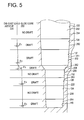
- the valve hole 110 is a cylindrical hole having a circular transverse cross sectional shape, and has a plurality of axial portions which have respective different diameters and which are coaxial with one another. Described more specifically, the valve hole 110 has different inner diameters which decrease in steps in its axial direction from its open end which is distant from the centerline of the housing of the compressor, toward its closed end which is nearer to the centerline of the housing.
- the valve hole 110 includes a plurality of straight inner circumferential surfaces 130, 132, 134 which have respective different constant diameters over respective axial lengths and which are spaced from each other in the axial direction of the valve hole 110.
- the straight inner circumferential surface 134 is located on the side of the closed end of the valve hole 110 which is nearer to the centerline of the housing.
- the diameter of the straight inner circumferential surface 130 located on the side of the open end of the valve hole 110 which is more distant from the centerline of the housing is larger than those of the other two straight inner circumferential surfaces 132, 134.
- tapered inner circumferential surfaces 136, 137, 138, 139, 140 are formed such that the tapered inner circumferential surfaces 136, 137, 138 are interposed between the two straight inner circumferential surfaces 130, 132, such that the tapered inner circumferential surface 139 is interposed between the two straight inner circumferential surfaces 132, 134, and such that the tapered inner circumferential surface 140 is located adjacent to the straight inner circumferential surface 134.
- the diameter of each of the tapered inner circumferential surfaces gradually increases in the axial direction of the valve hole 110 from the closed end which is nearer to the centerline of the housing toward the open end which is distant from the centerline of the housing.
- a sleeve 144 as one component of the pressure control device 90 is fitted in the valve hole 110 formed as described above.
- the sleeve 144 is a generally hollow cylindrical member including a plurality of axial portions having respective different diameters.
- the sleeve 144 consists of a plurality of members which are assembled together.
- the sleeve 144 has a plurality of straight outer circumferential surfaces 150, 152, 154 which have respective different constant diameters over respective axial lengths and which are spaced apart from each other in the axial direction of the sleeve 144. These straight outer circumferential surfaces 150, 152, 154 engage the straight inner circumferential surfaces 130, 132, 134 of the valve hole 110, respectively.
- Annular grooves are formed in the respective straight outer circumferential surfaces 150, 152, 154 of the sleeve 144 so as to extend in the circumferential direction.
- Sealing members in the form of O-rings 160, 162, 164 are fitted in the respective circumferential annular grooves of the straight outer circumferential surfaces 150, 152, 154 of the sleeve 144, so as to define, within the valve hole 110, three fluid-tightly sealed spaces (first through third spaces) which are arranged in the axial direction of the valve hole 110.
- the first space which is the nearest to the centerline of the housing, is held in communication with a discharge pressure chamber 170 formed in the sleeve 144 while communicating with the discharge chamber 24 via a high-pressure passage 180 formed in the rear housing 18.
- the second space which is intermediate between the first and third spaces, is held in communication with an annular chamber 174 formed in the sleeve 144 while communicating with the crank chamber 86 via a control pressure passage 176 (Fig. 1) formed through the rear housing 18 and the cylinder block 10.
- the third space which is the most distant from the centerline of the housing, is held in communication with a suction pressure chamber 178 formed in the sleeve 144 while communicating with the suction chamber 22 via a low-pressure passage 172 (Fig. 1).
- the high-pressure passage 180 and the control pressure passage 176 cooperate to constitute the supply passage 80.
- a valve element 190 is disposed within the discharge pressure chamber 170, and is biased by biasing means in the form of a compression coil spring 192 in a direction that causes the valve element 190 to be seated on a valve seat 196.
- a valve rod 200 is fitted in an engaging hole of the sleeve 144 such that the valve rod 200 is slidably moved in the axial direction.
- the valve element 190 is attached to the distal end of the valve rod 200 such that the valve element 190 is movable together with the valve rod 200.
- a bellows member 206 which is extensible and contractible.
- the bellows member 206 divides the inner space of the sleeve 144 into two annular sections, i.e., a radially outer section which functions as the above-described suction pressure chamber 178 and a radially inner section which functions as an atmospheric pressure chamber 208.
- the bellows member 206 is biased by biasing means in the form of a compression coil spring 210 in a direction of extension of the bellows member 206, in other words, toward the discharge pressure chamber 170.
- a holding member 212 which holds the distal end of the bellows member 206, and the valve rod 200 are connected to each other, so that a shut-off valve including the valve element 190 and the valve seat 196 is selectively opened and closed by advancing and the retracting movements of the valve rod 200 in response to extending and contracting movements of the bellows member 206.
- the bellows member 206 extends and contracts depending upon a suction pressure Ps introduced into the suction pressure chamber 178.
- the bellows member 206 contracts with an increase in the suction pressure Ps within the suction pressure chamber 178 while the bellows member 206 extends with a decrease in the suction pressure Ps.
- the bellows member 206 moves the valve rod 200 toward the discharge pressure chamber 170 when the suction pressure Ps in the suction pressure chamber 178 is lower than a predetermined value. Accordingly, the valve element 190 is moved away from the valve seat 196 against the biasing force of the compression coil spring 192, whereby the shut-off valve is opened to establish a fluid communication between the discharge chamber 24 and the crank chamber 86 via the high-pressure passage 180, discharge pressure chamber 170, annular chamber 174, and control pressure passage 176.
- the pressure control device 90 of the present embodiment is arranged to control the pressure Pc in the crank chamber 86 depending upon the change of the suction pressure Ps in the suction pressure chamber 178. Described in detail, where a cooling load required for air-conditioning the vehicle compartment is large, the suction pressure Ps is accordingly high, and exceeds the predetermined reference value. Accordingly, the bellows member 206 in the suction chamber 178 which is held in communication with the suction chamber 22 via the low-pressure passage 172 is contracted, whereby the valve element 190 is seated on the valve seat 196 so as to close the shut-off valve for inhibiting the fluid communication between the discharge pressure chamber 170 and the annular chamber 174.
- the suction pressure Ps is lowered with a decrease of the cooling load.
- the bellows member 206 is extended so as to advance the valve rod 200 toward the discharge pressure chamber 170, whereby the valve element 190 is moved away from the valve seat 196.
- the discharge pressure chamber 170 and the annular chamber 174 are brought into communication with each other, so that the refrigerant gas in the discharge chamber 24 is introduced into the crank chamber 86 via the high-pressure passage 180, discharge pressure chamber 170, annular chamber 174, and control pressure passage 176. Therefore, the pressure in the crank chamber 86 is increased to decrease the inclination angle of the swash plate 60, for thereby decreasing the displacement capacity of the compressor.
- the swash plate 60 With a further decrease in the suction pressure Ps, the swash plate 60 is placed in its minimum inclination position, whereby the displacement capacity of the compressor is minimized.
- the above-indicated portion (hereinafter referred to as " die-cast article 220") has the valve hole 110 for accommodating the pressure control device 90 constructed as described above.
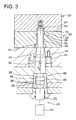
- Fig. 3 schematically shows a die-casting apparatus used in the present die-casting method. In the actual die-casting process, the above-indicated portion having the valve hole 110 is produced integrally with the other portions of the rear housing 18. Accordingly, the structure of the die-casting apparatus of Fig. 3 is different from that of the actual die-casting apparatus.
- the actual die-casting apparatus has a complicated structure including a stationary and a movable mold which are opened and closed, a plurality of moving members, and other components.
- a complicated structure including a stationary and a movable mold which are opened and closed, a plurality of moving members, and other components.
- the die-casting apparatus illustrated in a simplified manner in Fig. 3 includes a stationary mold 224 and a movable mold 226 which are moved toward and away from each other, so that the stationary and movable molds 224, 226 are opened and closed.
- the following explanation is made on the assumption that the die-casting apparatus illustrated in Fig. 3 is used in an ordinary casting system which includes a pair of stationary platens, and a movable platen which is disposed between the pair of stationary platens and which is moved toward and away from one of the stationary platens by actuation of a mold-opening-and-closing device such as a cylinder.
- the stationary mold 224 is attached to one of the opposite major surfaces of the above-indicated one stationary platen while the movable mold 226 is attached to one of the opposite major surfaces of the movable platen such that the stationary mold 224 and the movable mold 226 are opposed to each other with a high degree of positioning accuracy.
- Each of the stationary and movable molds 224, 226 consists of a plurality of plate members which are superposed on one another.
- the stationary and movable molds 224, 226 are opened and closed at respective contact surfaces 230, 232.
- the movable mold 226 is moved toward the stationary mold 224 by a drive force of a cylinder functioning as the mold-opening-and-closing-device, so that the two molds 224, 226 are closed with the contact surfaces 230, 232 being held in close contact with each other, for thereby defining a mold cavity 236 having a profile which follows that of the valve hole 110 of the die-cast article 220.
- the stationary mold 224 and the movable mold 226 have respective molding surfaces 242, 240 which cooperate with each other to provide an outer circumferential surface of the valve hole 110 of the die-cast article 220.
- the die-casting apparatus of the present embodiment includes a slide core 250 which forms an inner circumferential surface of the valve hole 110.
- a molten metal e.g., a molten aluminum alloy whose major component is aluminum
- the slide core 250 is held by the stationary mold 224 via a guide bushing 252 such that the slide core 250 is rotatable and axially movable relative to the stationary mold 224.
- the inner circumferential surface of the valve hole 110 is formed by the outer circumferential surface of the distal end portion of the slide core 250. As shown in Fig.
- the slide core 250 has a circular shape in transverse cross section and a plurality of axial portions which have respective different diameters and which are coaxial with one another.
- the slide core 250 includes straight outer circumferential surfaces 254, 256, 258 whose diameters are constant in the axial direction and which correspond to the straight inner circumferential surfaces 130, 132, 134 of the valve hole 110, respectively.
- the diameter of the outer circumferential surface of the slide core 250 decreases in the axial direction from its proximal end portion toward its distal end portion which forms the inner circumferential surface of the valve hole 110.
- a plurality of tapered outer circumferential surfaces 260, 261, 262, 263, 264 are formed such that the tapered outer circumferential surfaces 260, 261, 262 are interposed between the two straight outer circumferential surfaces 254, 256, such that the tapered outer circumferential surface 263 is interposed between the two straight outer circumferential surfaces 256, 258, and such that the tapered outer circumferential surface 264 is located adjacent to the straight outer circumferential surface 258.
- the tapered outer circumferential surfaces 260, 261, 262, 263, 264 have respective different angles of draft ⁇ 1 , ⁇ 2 , ⁇ 3 , ⁇ 4 , ⁇ 5 .
- These tapered outer circumferential surfaces 260, 262, 262, 263, 264 form the tapered inner circumferential surfaces 136, 137, 138, 139, 140 of the valve hole 110, respectively.
- the slide core 250 is axially moved by a drive device 270 relative to the stationary mold 224 while being rotated relative to the stationary mold 224.
- the drive device 270 includes an axial moving member 272 and a hydraulic cylinder 274.
- the axial moving member 272 is held by the stationary mold 224 such that the member 272 is axially movable relative to the stationary mold 224.
- the hydraulic cylinder 274 functions as an actuator for moving the axial moving member 272 in the axial direction.
- the axial moving member 272 is formed integrally with a piston rod of the hydraulic cylinder 274.
- the axial moving member 272 and the slide core 250 are connected to each other by a connecting device 280 such that the member 272 and the slide core 250 are rotatable relative to each other and axially immovable relative to each other.
- the connecting device 280 of the present embodiment includes a coupling member 282 having a cylindrical shape.
- the coupling member 282 has a first engaging recess 284 and a second engaging recess 290, each of which has a T shape in vertical cross section.
- An engaging protrusion 286 which is formed integrally with the slide core 250 and which has a T shape in vertical cross section engages the first engaging recess 284 such that the engaging protrusion 286 is rotatable and axially immovable relative to the first engaging recess 284.
- An engaging protrusion 292 which is formed integrally with the axial moving member 272 and which has a T shape in vertical cross section engages the second engaging recess 290 such that the engaging protrusion 292 is rotatable and axially immovable relative to the second engaging recess 290.
- a fitting sleeve 310 is fitted on the outer circumferential surface of the slide core 250 at an axially intermediate portion thereof.
- the fitting sleeve 310 is a cylindrical member.
- the fitting sleeve 310 is fixed to the stationary mold 224 by bolts 314 such that the fitting sleeve 310 is positioned with high accuracy relative to the stationary mold 224 by a positioning pin 312, preferably a plurality of positioning pins 312, and such that the fitting sleeve 310 is strictly prevented from rotating relative to the stationary mold 224.
- the fitting sleeve 310 fixed to the stationary mold 224 functions as a part of the stationary mold 224.
- the slide core 250 is provided with an engaging protrusion 300 which is located at its axial position corresponding to the fitting sleeve 310 and which radially outwardly extends from its outer circumferential surface.
- the fitting sleeve 310 is formed with an engaging groove 320 (Fig. 4) which is formed through the cylindrical wall and which engages the engaging protrusion 300 of the slide core 250.
- the engaging groove 320 includes an inclined portion 322 which extends in a direction inclined with respect to the axial direction of the slide core 250, and an axially extending portion 324 which is adjacent to the inclined portion 322 and which extends in a direction parallel to the axial direction of the slide core 250.
- the engaging protrusion 300 of the slide core 250 is positioned at one of the opposite ends of the inclined portion 322 of the engaging groove 320, which end is remote from the axially extending portion 324.
- the engaging protrusion 300 is moved relative to the fitting sleeve 310 along the inclined portion 322 of the engaging groove 320, whereby the slide core 250 is rotated while it is axially moved from its advanced position toward its retracted position.
- the hydraulic cylinder 274 constitutes the drive source operable to cause a relative axial movement of the slide core 250.
- the fitting sleeve 310 having the engaging groove 320, and the engaging protrusion 300 of the slide core 250 cooperate to constitute the motion-generating device operable to effect a relative rotation of the slide core 250 based on the relative axial movement described above.
- the engaging groove 320 constitutes the first engaging portion while the engaging protrusion 300 constitutes the second engaging portion.
- the engaging groove 320 having the inclined portion 322 may be formed in the slide core 250 while the engaging protrusion 300 may be formed on the fitting sleeve 310 (i.e., on the side of the stationary mold 224).
- the mold-opening-and-closing cylinder is actuated to move the movable mold 226 toward the stationary mold 224, so that the two molds 224, 226 are closed together with the contact surfaces 230, 232 being held in close contact with each other.
- the distal end portion of the slide core 250 is positioned in the mold cavity 236 which is defined by the two molds 224, 226 when they are closed together. In this state, the molten metal is introduced into the mold cavity 236.
- the molten metal solidifies into the die-cast article 220 a predetermined time after the molten metal has been introduced into the mold cavity 236.
- the valve hole 110 of the die-cast article 220 is formed by the outer circumferential surface of the slide core 250.
- the hydraulic cylinder 274 is actuated, so that the slide core 250 is rotated relative to the die-cast article 220 and retracted in the axial direction (as indicated by an arrow A in Fig. 3), by the engagement of the engaging protrusion 300 with the engaging groove 320 of the fitting sleeve 310.
- the slide core 250 can be easily removed from the die-cast article 220.
- the die-cast article 220 may suffer from defects called "chipping" at a portion of the inner circumferential surface which contacts the slide core 250.
- the die-cast article 220 produced by the present die-casting apparatus is free from such defects.
- the movable mold 226 is moved away from the stationary mold 224, whereby the two molds 224, 226 are opened.
- the die-cast article 220 is moved together with the movable mold 226 while being held by the movable mold 226.
- an ejecting device (not shown) provided in the movable mold 226 is actuated, for thereby pushing the die-cast article 220 in a direction away from the movable mold 226.
- the present arrangement wherein the slide core 250 can be easily removed from the die-cast article 220 permits formation of the inner circumferential surface of the die-cast article 220 by the slide core having a reduced angle of draft or no draft.
- the straight inner circumferential surfaces 130, 132, 134 of the valve hole 110 functioning as sealing surfaces which are held in sealing contact with the sealing members 160, 162, 164 of the sleeve 144 of the pressure control device 90 need to be formed as highly cylindrical surfaces without any taper while portions of the inner circumferential surface of the valve hole 110 other than those straight inner circumferential surfaces 130, 132, 134 need not to have a high degree of cylindricity.
- the slide core 250 does not have any draft on the straight outer circumferential surfaces 254, 256, 258 which respectively forms the straight inner circumferential surfaces 130, 132, 134 of the valve hole 110 that are required to have a high degree of cylindricity.
- the slide core 250 has respective different angles of draft provided on the respective portions of its outer circumferential surface other than the straight outer circumferential surfaces 254, 256, 258.
- the slide core 250 has the tapered outer circumferential surfaces 260, 262, 262, 263, 264, for easy removal of the slide core 250 from the die-cast article 220.
- the straight inner circumferential surfaces 130, 132, 134 of the valve hole 110 can be accurately formed as highly cylindrical surfaces without any taper
- the straight inner circumferential surfaces 130, 132, 134 need not be subjected to a machining operation after the die-casting process.
- the present embodiment at least reduces portions of the die-cast article which are subjected to the machining operation. Accordingly, the present embodiment is effective to reduce the time and cost required for the machining operation.
- valve hole 110 has the tapered inner circumferential surfaces 136 through 140 in the present embodiment
- the present arrangement is more effective to improve the yield, shorten the time required for the machining operation, and reduce the cost of manufacture of the die-cast article 220, than a conventional arrangement wherein the outer circumferential surface of the slide core for forming the inner circumferential surface of the valve hole is provided with a draft over the entire axial length so that the entire inner circumferential surface of the valve hole is required to be subjected to a machining operation to provide the tapered and straight inner circumferential surfaces.
- the straight inner circumferential surfaces 130, 132, 134 of the valve hole 110 formed according to the present embodiment remain uncut after the die-casting process, i.e., remain as-cast, there exists the chilled layer at the superficial portion of the inner circumferential surfaces, which chilled layer has high degrees of hardness and strength. Therefore, the die-cast article 220 exhibits high degrees of strength and wear resistance.
- the die-casting method and die-casting apparatus according to the present invention used for producing the die-cast article having the cylindrical hole can be employed for forming the inner circumferential surface of each of the cylinder bores 12 of the cylinder block 10 shown in Fig. 1 and the inner circumferential surface of the front housing 16. Since the head portion 72 of the piston 14 slidably moves on the inner circumferential surface of the cylinder bore 12 and the rotation preventive part formed integrally with the engaging portion 70 of the piston 14 is held in sliding contact with the inner circumferential surface of the front housing 16, those inner circumferential surfaces need to have a high degree of cylindricity. If the slide core is provided with a small angle of draft or no draft, the machining operation on those inner circumferential surfaces can be reduced or eliminated.
- the present die-casting method and die-casting apparatus permit the formation of the inner circumferential surface of the axial through-hole such as the inner circumferential surface of the cylinder bore 12, and the inner circumferential surface of the recess having a closed end such as the inner circumferential surface of the front housing 16.
- the slide core 250 is a molding portion.
- the stationary mold 224 and the movable mold 226 cooperate to constitute a mold assembly as a main body of the die-casting apparatus.
- the slide core 250 functions as a first molding member while the stationary and movable molds 224, 226 cooperate to function as a second molding member.
- the slide core 250 and the stationary mold 224 (the fitting sleeve 310) have respective two fitting surfaces which engage each other.
- the engaging groove 320 is formed in the fitting surface of the fitting sleeve 310 while the engaging protrusion 300 is formed on the fitting surface of the slide core 250.
- the die-casting apparatus may be arranged to have a member for forming an outer circumferential surface of a die-cast article.
- a die-casting apparatus constructed according to a second embodiment of the present invention for producing a die-cast article 426.
- the die-casting device of the second embodiment includes a stationary mold 402 and a movable mold 404 which are similar to the stationary mold 224 and the movable mold 226 of the above-described first embodiment.
- a movable sleeve 410 is held by the movable mold 404 such that the movable sleeve 410 is rotatable and axially movable relative to the movable mold 404.
- a drive device having a structure similar to that of the drive device 270 used in the first embodiment is connected to the movable sleeve 410.
- the movable sleeve 410 is fixed to a distal end of a rod 412.
- the rod 412 is axially moved while being rotated by the drive device.
- a detailed explanation of the drive device is dispensed with.
- the movable sleeve 410 has an inner circumferential surface 414 which is provided with a small angle of draft or no draft.
- the inner circumferential surface 414 of the movable sleeve 410 forms an outer circumferential surface 428 of a cylindrical protrusion 427 of the die-cast article 426.
- the stationary and movable molds 402, 404 have respective molding surfaces 420, 422 which cooperate with the inner circumferential surface 414 of the movable sleeve 410 to define a mold cavity 430 having a configuration which follows that of the die-cast article 426 to be produced.
- the movable sleeve 410 can be easily removed from the die-cast article 426 while the movable sleeve 410 is rotated as indicated by an arrow A in Fig. 6. Accordingly, the outer circumferential surface 428 of the cylindrical protrusion 427 of the die-cast article 426 has no taper or a small taper angle.
- the movable sleeve 410 is the molding portion.
- the movable sleeve 410 also functions as the first molding member while the stationary mold 402 and the movable mold 404 cooperate to function as the second molding member.
- a die-casting apparatus for practicing the method is also disclosed.
Landscapes
- Engineering & Computer Science (AREA)
- Mechanical Engineering (AREA)
- Molds, Cores, And Manufacturing Methods Thereof (AREA)
Applications Claiming Priority (2)
| Application Number | Priority Date | Filing Date | Title |
|---|---|---|---|
| JP2001112310A JP2002307156A (ja) | 2001-04-11 | 2001-04-11 | ダイキャスト方法および金型装置 |
| JP2001112310 | 2001-04-11 |
Publications (2)
| Publication Number | Publication Date |
|---|---|
| EP1249289A2 true EP1249289A2 (fr) | 2002-10-16 |
| EP1249289A3 EP1249289A3 (fr) | 2003-03-05 |
Family
ID=18963752
Family Applications (1)
| Application Number | Title | Priority Date | Filing Date |
|---|---|---|---|
| EP02008010A Withdrawn EP1249289A3 (fr) | 2001-04-11 | 2002-04-10 | Procédé et dispositif de coulée sous pression |
Country Status (3)
| Country | Link |
|---|---|
| US (1) | US20020148591A1 (fr) |
| EP (1) | EP1249289A3 (fr) |
| JP (1) | JP2002307156A (fr) |
Cited By (2)
| Publication number | Priority date | Publication date | Assignee | Title |
|---|---|---|---|---|
| CN103567412A (zh) * | 2012-07-18 | 2014-02-12 | 加特可株式会社 | 机械零件或电子零件的制造方法 |
| CN106583684A (zh) * | 2016-12-30 | 2017-04-26 | 宁波环亚机械制造有限公司 | 交叉抽芯压铸模 |
Families Citing this family (4)
| Publication number | Priority date | Publication date | Assignee | Title |
|---|---|---|---|---|
| JP5597984B2 (ja) * | 2009-12-16 | 2014-10-01 | 株式会社デンソー | 内径形成部等を高精度に鋳造する鋳造装置 |
| CN113523222B (zh) * | 2021-06-23 | 2023-09-15 | 东风(十堰)有色铸件有限公司 | 一种汽车结构件用高性能压铸铝合金材料的设备 |
| CN113579195B (zh) * | 2021-08-03 | 2023-06-16 | 东风(十堰)有色铸件有限公司 | 一种电动车变速箱壳体压铸工艺装置 |
| CN113770335B (zh) * | 2021-08-04 | 2023-09-22 | 安徽锦晟汽车工业有限公司 | 一种铝棒加工熔铸模具 |
Citations (1)
| Publication number | Priority date | Publication date | Assignee | Title |
|---|---|---|---|---|
| EP1036941A2 (fr) * | 1999-03-15 | 2000-09-20 | Kabushiki Kaisha Toyoda Jidoshokki Seisakusho | Filtre pour compresseur |
Family Cites Families (3)
| Publication number | Priority date | Publication date | Assignee | Title |
|---|---|---|---|---|
| US2579952A (en) * | 1950-06-16 | 1951-12-25 | Louis H Morin | Method of forming threaded die castings |
| US4958676A (en) * | 1989-05-30 | 1990-09-25 | Hubbell Incorporated | Die casting apparatus for casting articles with an internally threaded bore |
| JP3034827B2 (ja) * | 1997-08-07 | 2000-04-17 | 株式会社南武 | ロッド回動式シリンダ装置 |
-
2001
- 2001-04-11 JP JP2001112310A patent/JP2002307156A/ja active Pending
-
2002
- 2002-04-04 US US10/116,471 patent/US20020148591A1/en not_active Abandoned
- 2002-04-10 EP EP02008010A patent/EP1249289A3/fr not_active Withdrawn
Patent Citations (1)
| Publication number | Priority date | Publication date | Assignee | Title |
|---|---|---|---|---|
| EP1036941A2 (fr) * | 1999-03-15 | 2000-09-20 | Kabushiki Kaisha Toyoda Jidoshokki Seisakusho | Filtre pour compresseur |
Cited By (3)
| Publication number | Priority date | Publication date | Assignee | Title |
|---|---|---|---|---|
| CN103567412A (zh) * | 2012-07-18 | 2014-02-12 | 加特可株式会社 | 机械零件或电子零件的制造方法 |
| CN106583684A (zh) * | 2016-12-30 | 2017-04-26 | 宁波环亚机械制造有限公司 | 交叉抽芯压铸模 |
| CN106583684B (zh) * | 2016-12-30 | 2018-08-14 | 宁波环亚机械制造有限公司 | 交叉抽芯压铸模 |
Also Published As
| Publication number | Publication date |
|---|---|
| US20020148591A1 (en) | 2002-10-17 |
| JP2002307156A (ja) | 2002-10-22 |
| EP1249289A3 (fr) | 2003-03-05 |
Similar Documents
| Publication | Publication Date | Title |
|---|---|---|
| EP1243363A2 (fr) | Procédé et dispositif de coulée sous pression | |
| US6530149B2 (en) | Method for producing hollow piston for compressor by forging | |
| KR100445044B1 (ko) | 슈우의 제조방법 | |
| EP0809025A1 (fr) | Piston pour compresseur à piston | |
| US6453555B1 (en) | Method of producing compressor piston | |
| EP1249289A2 (fr) | Procédé et dispositif de coulée sous pression | |
| EP1225338A2 (fr) | Compresseur à spirales | |
| KR0158508B1 (ko) | 왕복 운동형 압축기 | |
| US20030088979A1 (en) | Method of producing aluminum ball, method of producing compressor shoe, and compressor shoe produced by the method | |
| US20020170425A1 (en) | Shoe for swash plate type compressor and method of producing the same | |
| EP1087135A2 (fr) | Piston creux d'un compresseur à plateau en biais non axisymétrique | |
| US6453554B1 (en) | Swash plate type compressor piston wherein inner surface of base section of neck portion has as-cast surface area | |
| EP1094219B1 (fr) | Piston de compresseur à plateau en biais avec tête de piston coulée sans pores | |
| KR20030074110A (ko) | 사판식 압축기용 슈 및 그 성형방법 | |
| JP4132606B2 (ja) | 圧縮機用ピストンの製造方法 | |
| US6378416B1 (en) | Swash plate type compressor piston wherein inner surface of hollow cylindrical section of body portion has axially extending reinforcing projections | |
| EP1193394B1 (fr) | Barillet pour machine rotative à pistons | |
| EP1087136B1 (fr) | Tête de piston de compresseur à plateau en biais avec chanfrein | |
| JP2001107853A (ja) | 斜板式圧縮機用ピストンの製造方法 | |
| JP2002192294A (ja) | 球冠状シューの製造方法 | |
| US20010047720A1 (en) | Compressor piston and process for producing the compressor piston | |
| JP2001263240A (ja) | 圧縮機用中空ピストンの製造方法 | |
| JPH07127568A (ja) | 圧縮機のシリンダヘッド | |
| JPH06304691A (ja) | アルミニウム合金製ローターの製造方法 | |
| JP2003193968A (ja) | ピストン及びその製造方法 |
Legal Events
| Date | Code | Title | Description |
|---|---|---|---|
| PUAI | Public reference made under article 153(3) epc to a published international application that has entered the european phase |
Free format text: ORIGINAL CODE: 0009012 |
|
| 17P | Request for examination filed |
Effective date: 20020410 |
|
| AK | Designated contracting states |
Kind code of ref document: A2 Designated state(s): AT BE CH CY DE DK ES FI FR GB GR IE IT LI LU MC NL PT SE TR |
|
| AX | Request for extension of the european patent |
Free format text: AL;LT;LV;MK;RO;SI |
|
| PUAL | Search report despatched |
Free format text: ORIGINAL CODE: 0009013 |
|
| AK | Designated contracting states |
Kind code of ref document: A3 Designated state(s): AT BE CH CY DE DK ES FI FR GB GR IE IT LI LU MC NL PT SE TR Designated state(s): AT BE CH CY DE DK ES FI FR GB GR IE IT LI LU MC NL PT SE TR |
|
| AX | Request for extension of the european patent |
Extension state: AL LT LV MK RO SI |
|
| RIC1 | Information provided on ipc code assigned before grant |
Ipc: 7B 22D 17/20 B Ipc: 7B 22D 17/24 B Ipc: 7B 22D 17/22 A |
|
| 17Q | First examination report despatched |
Effective date: 20030526 |
|
| AKX | Designation fees paid |
Designated state(s): DE FR IT |
|
| STAA | Information on the status of an ep patent application or granted ep patent |
Free format text: STATUS: THE APPLICATION IS DEEMED TO BE WITHDRAWN |
|
| 18D | Application deemed to be withdrawn |
Effective date: 20040603 |