EP1248232B1 - Bildverzerrung - Google Patents
Bildverzerrung Download PDFInfo
- Publication number
- EP1248232B1 EP1248232B1 EP02007758A EP02007758A EP1248232B1 EP 1248232 B1 EP1248232 B1 EP 1248232B1 EP 02007758 A EP02007758 A EP 02007758A EP 02007758 A EP02007758 A EP 02007758A EP 1248232 B1 EP1248232 B1 EP 1248232B1
- Authority
- EP
- European Patent Office
- Prior art keywords
- image
- deformed
- original
- original image
- model
- Prior art date
- Legal status (The legal status is an assumption and is not a legal conclusion. Google has not performed a legal analysis and makes no representation as to the accuracy of the status listed.)
- Expired - Lifetime
Links
Images


Classifications
-
- G—PHYSICS
- G06—COMPUTING OR CALCULATING; COUNTING
- G06T—IMAGE DATA PROCESSING OR GENERATION, IN GENERAL
- G06T3/00—Geometric image transformations in the plane of the image
- G06T3/04—Context-preserving transformations, e.g. by using an importance map
- G06T3/047—Fisheye or wide-angle transformations
Definitions
- This invention relates to 3-D (dimensional) image processing technology for performing prescribed image processing to generate, on a display screen, a deformed image obtained by intentional distortion of an original image, for use in for example video game equipment or similar.
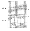
- Fig. 7A an original image (a normal image, not appearing to have been taken through a fisheye lens) is divided into small images of a prescribed size.
- Fig. 7B an elliptical region EP (called the "fisheye region") with center at the image center is described, and each of the small image regions is deformed such that the image in this region appears to have been photographed through a fisheye lens.
- each of the small images in Fig. 7A is textured, deformed into the corresponding region in Fig. 7B, and pasted into the region.
- Fig. 9 is an image obtained by performing fisheye processing, using the method described above, on the original image shown in Fig. 8. As shown in Fig. 9, in the vicinity of the outer border of the fisheye region, straight lines in the original image are deformed into broken-line shapes to form an unnatural image, whereas in the case of actual photography through a fisheye lens, straight lines in the original image are deformed into smooth curves.
- EP-A-0 989 524 relates to a method for integration of three-dimensional computer graphics and a two-dimensional image to provide a realistic three-dimensional virtual reality experience.
- a display technique for three-dimensional virtual reality is disclosed, wherein the two-dimensional image is distorted so as to adjust the image's vanishing point(s) in accordance with a movement of the user using a pyramidic panel structure.
- the present invention is defined by the appended claims. It was devised in light of the above problem, and has as an object the provision of a 3-D image processing method and device, a 3-D image processing program, and a video game device which generate, on a display screen, a natural-looking deformed image obtained by intentionally distorting an original image.
- an original image and a 3-D polygon model comprising a plurality of polygons and having a shape in which at least a portion of a plane is distorted in 3-D space, are stored; the original image is read out and textured, and is pasted onto the polygon model, and an image of the polygon model onto which the original image is pasted, and which is seen from a prescribed camera viewpoint, is drawn on a display screen, to obtain a natural-looking deformed image as a result of intentional distortion of the original image.
- Fig. 1 is a block diagram showing one aspect of a video game device of this invention.
- This video game device comprises a game main unit GM and recording medium 200 on which is recorded program data.
- the game main unit GM comprises a CPU (central processing unit) 1; a bus line 2 connected to the CPU 1 and having an address bus, data bus, and control bus; and a graphic data generation processor 3.
- the bus line 2 is connected to an interface 4; RAM (random access memory) or other main memory 5; ROM (read-only memory) 6; an expansion circuit 7; a parallel port 8; a serial port 9; a drawing processor 10; an audio processor 11; a decoder 12; and an interface circuit 13.
- the drawing processor 10 is connected to a buffer 21, and also to a television monitor (hereafter "monitor") 22; the audio processor 11 is connected to a buffer 23, and to a speaker 25 via an amplifier circuit 24.
- the decoder 12 is connected to a buffer 26, and also to a recording medium driver 27; the interface circuit 13 is connected to memory 28, and also to a controller 29.
- this video game device changes according to the application.
- the monitor 22 and speaker 25 are separate from the game main unit GM.
- the video game device is configured for commercial use, all the component elements shown in Fig. 1 are housed in a single housing.
- the monitor 22 corresponds to the computer display;
- the drawing processor 10, audio processor 11, and expansion circuit 7 correspond to a portion of the program data recorded on the recording medium 200 or to hardware on an expansion board mounted in an expansion slot of the computer;
- the interface circuit 4, parallel port 8, serial port 9, and interface circuit 13 correspond to hardware on an expansion board mounted on an expansion slot of the computer.
- the buffers 21, 23, 26 correspond to areas in main memory 5 or in expansion memory (not shown). In this aspect, an example is explained for the case in which the video game device is configured for home use.
- the graphic data generation processor 3 plays a role similar to that of a coprocessor of the CPU 1. That is, the graphic data generation processor 3 employs parallel processing to execute coordinate conversions, light source calculations, and, for example, matrix and vector operations in fixed-decimal point format.
- the main processing tasks performed by this graphic data generation processor 3 is to determine addresses in the display area of the image being processed based on coordinate data for each vertex in image data supplied by the CPU 1 in 2- or 3-D space, movement amount data, and rotation amount data, and to return this data to the CPU 1, as well as to calculate image brightness according to distances from a virtually set light source.
- the interface circuit 4 is an interface for use with a peripheral device, such as a mouse, trackball, or other pointing device.
- the ROM 6 stores program data as the operating system for the video game device. In terms of personal computers, this corresponds to the BIOS (basic input/output system).
- the expansion circuit 7 performs processing to expand compressed images which have been compressed by intra-frame coding conforming to the MPEG (Moving Picture Engineering Group) standard for video and the JPEG (Joint Picture Engineering Group) standard for still images.
- Expansion processing is decoding processing (decoding of data encoded using a VLC, or variable-length code), inverse quantization processing, IDCT (inverse discrete cosine transform) processing, processing to restore intra-frame-coded images, and similar.
- the buffer 21 is RAM or similar, and comprises a display area (frame buffer) and non-display area.
- the display area is an area for expansion of data to be displayed on the display screen of the monitor 22.
- the non-display area comprises areas for storage of texture data and color palette data, in addition to data defining a skeleton, model data defining polygons, animation data to cause models to move, and pattern data representing the details of animation.
- texture data is 2-D image data.
- Color palette data is data to specify the colors of texture data and other data. These data types are recorded in the non-display area of the buffer 21 in advance by the CPU 1 from the recording medium 200, either all at once, or divided into a plurality of events according to the game progress.
- Drawing instructions include instructions to draw quasi-3-D images using polygons, and instructions to draw normal 2-D images.
- polygons are virtual 2-D polygonal shapes; in this aspect, quadrilaterals are used.
- Drawing instructions to draw 3-D images using polygons are executed for polygon vertex address data in the display area of the buffer 21; texture address data indicating storage positions in the buffer 21 of texture data to be pasted onto polygons; color palette address data indicating storage positions in the buffer 21 of color palette data, indicating colors for texture data; and brightness data indicating brightnesses for textures.
- polygon vertex address data in the display area is obtained when the graphic data generation processor 3 substitutes polygon vertex coordinate data in 3-D space from the CPU 1 with polygon vertex coordinate data in 2-D, by performing a coordinate conversion based on movement amount data and rotation amount data for the screen itself.
- Brightness data is determined by the graphic data generation processor 3, based on distances from the positions from the CPU 1 indicated by polygon vertex coordinate data after the above coordinate conversion, to the virtually positioned light source.
- the above polygon vertex address data indicates the address in the display area of the buffer 21; the drawing processor 10 performs processing to write texture data corresponding to the range in the display area of the buffer 21 indicated by three polygon vertex addresses.
- the characters and other objects within a virtual game space are configured from numerous polygons.
- the CPU 1 stores coordinate data in 3-D space for each polygon in the buffer 21, associated with skeleton vector data.
- the CPU 1 provides the graphic data generation processor 3 with 3-D coordinate data for the vertices of each polygon held within the non-display area of the buffer 21, as well as movement amount data and rotation amount data for each polygon, determined from the skeleton coordinates and rotation amount data.
- the graphic data generation processor 3 determines 3-D coordinate data for each polygon in succession after movement and rotation, based on the 3-D coordinate data for each polygon, and the movement amount data and rotation amount data for each polygon. Of the 3-D coordinate data for each polygon obtained in this way, coordinate data in the horizontal and vertical directions is supplied to the drawing processor 10 as address data in the display area of the buffer 21, that is, as polygon vertex address data.
- the drawing processor 10 writes texture data indicated by texture address data, allocated in advance, to a triangular display area in the buffer 21 indicated by three polygon vertex addresses. By this means, an object is displayed on the display screen of the monitor 22 by pasting texture data onto numerous polygons.
- Drawing instructions to draw normal 2-D images are performed for vertex address data; texture address data; color palette address data, indicating storage positions in the buffer 21 of color palette data indicating colors for texture data; and brightness data, indicating the brightness of textures.
- the vertex address data is coordinate data obtained by the graphic data generation processor 3 by coordinate conversion of vertex coordinate data in a 2-D plane from the CPU 1, based on movement amount data and rotation amount data.
- the audio processor 11 stores ADPCM (adaptive differential pulse code modulation) data read from the storage medium 200 in the buffer 23, and employs this ADPCM data stored in the buffer 23 as a sound source.
- the audio processor 11 reads the ADPCM data based on a clock signal at, for example, a frequency of 44.1 kHz.
- the audio processor 11 performs processing of the ADPCM data read from the buffer 23 to convert the pitch, add noise, set the envelope and level, add reverb, and similar.
- audio data read from the storage medium 200 is CD-DA (compact disc digital audio) or other PCM data
- the data is converted into ADPCM data by the audio processor 11.
- Processing of PCM data by program data is performed directly in main memory 5.
- PCM data that has been processed in main memory 5 is supplied to the audio processor 11, and after conversion into ADPCM data, the various types of processing described above are performed, after which the result is output as an audio signal to the speaker 25.
- the recording medium driver 27 is, for example, a CD-ROM drive, hard disk drive, optical disk drive, flexible disk drive, silicon disk drive, cassette medium reader, or similar.
- the recording medium 200 is, for example, a CD-ROM, hard disk, optical disk, flexible disk, semiconductor memory, or similar.
- the recording medium driver 27 reads image, audio, and program data from the recording medium 200, and supplies data which has been read to the decoder 12.
- the decoder 12 performs error correction processing using an ECC (error correction code) on the reproduced data from the recording medium driver 27, and supplies the error-corrected data to main memory 5 or to the audio processor 11.
- the memory 28 comprises, for example, holder or card-type memory. Card-type memory is used to hold various game parameters when the game is interrupted, as for example when saving the state of a game which is interrupted before ending.
- the controller 29 is an operation means enabling operation from outside, and comprises a first left button 29L1, second left button 29L2, first right button 29R1, second right button 29R2, upward key 29U, downward key 29D, leftward key 29L, rightward key 29R, start button 29a, select button 29b, first button 29c, second button 29d, third button 29e, fourth button 29f, left joystick 29SL, and right joystick 29SR; operation signals are output to the CPU 1 according to operation by the player.
- the upward key 29U, downward key 29D, leftward key 29L, and rightward key 29R are used by the player to send commands to the CPU 1 causing, for example, a character or cursor to move upward, downward, leftward, or rightward on the screen of the monitor 22.
- the start button 29a is used by the player to instruct the CPU 1 to start game program data which has been loaded from the recording medium 200.
- the select button 29b is used by the player to instruct the CPU 1 regarding various selections with respect to game program data loaded into main memory 5 from the recording medium 200.
- buttons and keys of the controller 29, with the exceptions of the left joystick 29SL and right joystick 29SR, are on-off switches that are turned on upon being depressed from a neutral position by a depressing force from outside, and which are restored to the above neutral position when the depressing force is released.
- the left joystick 29SL and right joystick 29SR are stick-type controllers with essentially the same configurations as an ordinary joystick. That is, each has an upright stick, configured so as to be capable of tilting through 360°, including forward, backward, right and left, about a prescribed position of the stick as a fulcrum.
- values for the lateral-direction x-coordinate and anteroposterior-direction y-coordinate, corresponding to the direction of tilt and angle of tilt of the stick, are sent as operation signals to the CPU 1 via the interface circuit 13.
- the functions of the first left button 29L1, second left button 29L2, first right button 29R1, and second right button 29R2 differ depending on the game program data loaded from the recording medium 200.
- a power supply switch (not shown) is turned on to supply power to the video game device.
- the CPU 1 instructs the recording medium driver 27 to read program data from the recording medium 200.
- the recording medium driver 27 reads image, audio, and program data from the recording medium 200.
- the image, audio, and program data thus read is supplied to the decoder 12, which performs error correction processing.
- Image data which has been error-corrected by the decoder 12 is supplied to the expansion circuit 7 via the bus line 2; after the above-described expansion processing has been performed, the result is supplied to the drawing processor 10, and this drawing processor 10 writes the data to the non-display area of the buffer 21.
- Audio data which has been error-corrected by the decoder 12 is either written to main memory 5, or supplied to the audio processor 11 and written to the buffer 23.
- Program data which has been error-corrected by the decoder 12 is written to main memory 5.
- the CPU 1 advances the game based on game program data stored in main memory 5 and the details of instructions issued by the player via the controller 29. That is, the CPU 1 controls image processing, audio processing, and internal processing as appropriate, based on the details of instructions issued by the player via the controller 29.
- image processing control is performed to, for example, calculate skeleton coordinates and polygon vertex coordinate data from pattern data related to animation which characters are instructed to exhibit; supply the obtained 3-D coordinate data and viewpoint position data to the graphic data generation processor 3; and issue drawing instructions for data including address data and brightness data in the non-display area of the buffer 21, determined by the graphic data generation processor 3.
- Audio processing control is performed to, for example, issue audio output commands to the audio processor 11, and to specify level, reverb, or other parameters.
- Internal control is performed to, for example, perform computations according to operation of the controller 29.
- Image data which has been error-corrected by the decoder 12 is supplied to the expansion circuit 7 via the bus line 2, and after performing the expansion processing described above, is supplied to the drawing processor 10; the drawing processor 10 writes the data to the non-display area of the buffer 21.
- Audio data which has been error-corrected by the decoder 12 is either written to main memory 5, or is supplied to the audio processor 11 and written to the buffer 23.
- Program data which has been error-corrected by the decoder 12 is written to main memory 5.
- the CPU 1 advances the game based on game program data stored in main memory 5 and the details of instructions issued by the player via the controller 29. That is, the CPU 1 controls image processing, audio processing, and internal processing as appropriate, based on the details of instructions issued by the player via the controller 29.
- Fig. 2 is a block diagram showing the principal components of a 3-D image processing device of this invention.
- the buffer 21 comprises an original image storage section 210 which stores original images; a model storage section 211 which stores a 3-D model, comprising a plurality of polygons, and having a shape obtained by distorting in 3-D space at least a portion of a plane; a deformed image storage section 212 which stores a deformed image, described below; and a frame buffer (display area) 213.
- the original image storage section 210, model storage section 211, and deformed image storage section 212 are comprised by the non-display area, previously described.
- the original image storage section 210 comprises a first original image storage section 2101 and a second original image storage section 2102, which respectively store a first original image and second original image, taken from different camera viewpoints.
- the drawing processor 10 comprises an image pasting section 100, which reads the first original image from the first original image storage section 2101, reads the 3-D model from the model storage section 211, and pastes the above first original image, as a texture, onto the above 3-D model; a deformed image drawing section 101, which, by writing to the frame buffer 213, draws on the monitor 22 a deformed image which is the image of the above 3-D model onto which an original image is pasted, seen from a prescribed camera viewpoint, and stores the drawn deformed image in the deformed image storage section 212; a model deformation section 102, which reads the 3-D model from the model storage section 211, deforms the 3-D model, and stores the result in the model storage section 211; an image composition section 103, which reads a deformed image from the deformed image storage section 212, reads the second original image from the second original image storage section 2102, and combines the deformed image and second original image to create a composite image; and, a composite image drawing section 104, which, by
- Fig. 3A and Fig. 3B show examples of a 3-D model stored in the model storage section 211.
- the 3-D model has the shape of a plane FM, having a rectangular outer perimeter, joined to a curved surface EM1 (EM2) formed by cutting a curved surface in the shape of an ellipsoid of revolution by the above plane FM.
- the boundary line EE1 (EE2) of the plane FM and curved surface EM1 (EM2) is an ellipse.
- Fig. 3A shows the case in which the curved surface EM1 is convex on the camera viewpoint side
- Fig. 3B shows the case in which the curved surface EM2 is convex on the camera viewpoint side.
- the 3-D model is deformed by the model deformation section 102, by expansion and contraction of the curved surface of the above ellipsoid of revolution in the direction perpendicular to the plane FM.
- the extent of distortion of the deformed image compared with the original image can be modified.
- the image pasting section 100 reads the first original image from the first original image storage section 2101, and reads the 3-D model from the model storage section 211.
- the above first original image is divided into small images of a prescribed size, as shown in Fig. 7A, and deforms each small image as a texture and pastes it into the corresponding region of the 3-D model, as shown for example in Fig. 3A.
- the deformed image drawing section 101 draws on the monitor 22 the deformed image, which is an image of the 3-D model onto which the original image is pasted by the image pasting section 100, as seen from a prescribed camera viewpoint, and stores the drawn deformed image in the deformed image storage section 212.
- the above prescribed camera viewpoint is on a straight line, perpendicular to the plane FM comprised by the 3-D model shown in Fig. 3A, and which passes through the approximate center of the plane.
- the image composition section 103 reads the deformed image from the deformed image storage section 212, reduces the image, reads the second original image from the second original image storage section 2102, and combines the reduced deformed image and the second original image into an image on one screen, to create a composite image.
- Fig. 4 is a flowchart showing in summary 3-D image processing of this invention.
- the image pasting section 100 performs the following processing.
- the first original image is read from the first original image storage section 2101 (ST1).
- the 3-D model is read from the model storage section 211 (ST3).
- the first original image is pasted, as a texture, onto the 3-D model (ST5).
- the deformed image drawing section 101 draws on the monitor 22 a deformed image, which is an image of the 3-D model, onto which the original image is pasted, as seen from a prescribed camera viewpoint, and then stores the drawn deformed image in the deformed image storage section 212 (ST7).
- the image composition section 103 reads the deformed image from the deformed image storage section 212, reads the second original image from the second original image storage section 2102 (ST9), and combines the deformed image and the second original image in an image on a single screen to create a composite image (ST11).
- the composite image drawing section 104 draws the composite image on the monitor 22 (ST13).
- Fig. 5 is a drawing of an screen obtained by performing the 3-D image processing of this invention on the original image shown in Fig. 8.
- the first original image and second original image are the same image, shown in Fig. 8.
- a wall model WM with a lattice-shape pattern, a floor model FM with a brick pattern, and a human model HM, with one foot resting on a skateboard model SM are drawn.
- the image shown in Fig. 5 comprises a large screen region MSC, displaying the second original image, and a small screen region SSC, displaying a deformed image obtained from the first original image. In this way, by displaying the original image in the large screen region MSC and a deformed image in the small screen region SSC, an image with a heightened sense of presence is obtained.
- Fig. 6 shows a full-screen view of the deformed image of the first original image displayed in the small screen region SSC of Fig. 5, displayed on the entire screen.
- the deformed image of Fig. 9 obtained by the conventional method in the vicinity of the outer border EE of the fisheye region, the image is unnaturally distorted, and straight lines in the original image are deformed into broken-line shapes to form an unnatural image.
- the deformed image obtained by the method of this invention and shown in Fig. 6 even in the vicinity of the outer border EE of the fisheye region straight lines are deformed into curves, and a natural-looking image is obtained.
- the present invention can take the following aspects.
- the 3-D image processing program of this invention is, for example, stored in advance in the recording medium 200, is transferred from the recording medium 200 to main memory 5, and processing is executed by the drawing processor 10 based on program data stored in main memory 5.
- the present invention relates to a computer readable recording medium storing a 3-D image processing program, which intentionally distorts an original image to generate a deformed image on a display screen.
- the 3-D image processing program comprises the steps of:
- the present invention relates also to a 3-D image processing method, which intentionally distorts an original image to generate a deformed image on a display screen.
- the method comprises the steps of:
- the present invention also relates to a 3-D image processing device, which intentionally distorts an original image to generate a deformed image on a display screen, comprising:
- an original image and a 3-D polygon model comprising a plurality of polygons and having a shape in which at least a portion of a plane is distorted in 3-D space, are stored; the original image is read out and textured, and is pasted onto the polygon model, and an image of the polygon model onto which the original image is pasted, and which is seen from a prescribed camera viewpoint, is drawn on a display screen, to obtain a natural-looking deformed image as a result of intentional distortion of the original image.
- an original image, and a 3-D polygon model comprising a plurality of polygons and having a shape in which at least a portion of a plane is distorted in 3-D space are stored; the original image is read, and is pasted as a texture onto the polygon model; and an image of the polygon model onto which the original image has been pasted, as seen from a prescribed camera viewpoint, is drawn on a display screen, so that a natural-looking deformed image, in which the original image has been intentionally distorted, is obtained.
- said 3-D model preferably has a shape in which a plane, having a rectangular outer perimeter, is joined with a curved surface obtained by cutting the curved surface of an ellipsoid of revolution by said plane.
- the 3-D model has the shape of a plane having a rectangular outer perimeter joined to a curved surface which is an ellipsoid of revolution cut by the above plane, using deformed image drawing means, the portion of an image pasted onto the curved surface of the ellipsoid of revolution becomes a deformed image, deformed in the manner of an image photographed through a fisheye lens.
- the 3-D model has a shape obtained by joining a plane having a rectangular outer perimeter, and a curved surface formed by cutting the curved surface of an ellipsoid of revolution by the above plane; consequently from the portion of the image pasted onto the curved surface of the ellipsoid of revolution is obtained, through deformed image drawing means, a deformed image, which is deformed in the manner of an image photographed through a fisheye lens.
- model deformation processing is preferably performed in which said 3-D model is deformed by expansion or contraction of the curved surface of said ellipsoid of revolution in the direction perpendicular to said plane.
- the curved surface of the ellipsoid of revolution is expanded and contracted in the direction perpendicular to the plane during model deformation processing, and the 3-D model is deformed, so that from the portion of the image pasted onto the curved surface of the ellipsoid of revolution, a deformed image with different extents of deformation, similar to the image deformation of an image which has been photographed through fisheye lenses with various extents of deformation, can easily be obtained.
- said prescribed camera viewpoint is preferably situated on a straight line perpendicular to the plane comprised by said 3-D model, and passing through the approximate center of the plane.
- the camera viewpoint is on a line perpendicular to the plane and passing through the approximate center of the plane comprised by the 3-D model, a naturally deformed image is obtained, similar to an image photographed through a fisheye lens from a camera viewpoint on the axis of the fisheye lens.
- the camera viewpoint 3 is situated on a straight line which is perpendicular to the plane and passes through the approximate center of the plane comprised by the three-D model, so that a natural-looking deformed image, similar to an image photographed through a fisheye lens from a camera viewpoint on the axis of the fisheye lens, can be obtained.
- said 3-D image processing program preferably further comprises the steps of storing said deformed image, drawn by a deformed image drawing processing; performing said image composition processing in which the second original image and the deformed image are read, and the image is composed on the single screen; and performing composite image drawing processing.
- said 3-D image processing program preferably further comprises the steps of storing said deformed image, drawn by a deformed image drawing processing; performing said image composition processing in which the second original image and the deformed image are read, and the image is composed on the single screen; and performing composite image drawing processing.
- a first original image and a second original image which are two original images taken from different camera viewpoints, are stored; a deformed image of the first original image is stored; and, in said image composition processing, the second original image and the deformed image are combined.
- a composite image obtained by composition of a deformed image of one of the original images and the other original image, is drawn on the display screen, so that the drawn composite image appears to have been photographed by two cameras, and the sense of presence is further heightened.
- a composite image is created by combining one of the original images and a deformed image of the other original image, and is drawn on a display screen; consequently the drawn composite image appears to have been photographed by two cameras, and the sense of presence is further heightened.
- the present invention also takes a form of a video game device, which comprises the above described 3-D image processing device according to the invention.
- a video game device is realized in which, by means of the 3-D image processing device, a natural-looking deformed image is obtained as a result of intentional distortion of an original image, and the deformed image is displayed on the image display means according to game program data recorded by the program storage means.
- a natural-looking deformed image in which an original image is intentionally distorted is obtained by means of a 3-D image processing device, and a video game device is realized in which a deformed image is displayed by image display means according to game program data recorded in program storage means.
Landscapes
- Physics & Mathematics (AREA)
- General Physics & Mathematics (AREA)
- Engineering & Computer Science (AREA)
- Theoretical Computer Science (AREA)
- Processing Or Creating Images (AREA)
- Image Generation (AREA)
- Image Processing (AREA)
Claims (9)
- 3-D-Bild-Bearbeitungsprogramm, welches bewußt bzw. absichtlich ein Originalbild verzerrt, um ein deformiertes bzw. verformtes Bild auf einem Anzeigeschirm (22) zu generieren bzw. zu erzeugen, wobei das Programm die Schritte umfaßt:Speichern eines ersten Originalbilds und eines 3-D-Modells, , umfassend eine Mehrzahl von Polygonen, wobei das 3-D-Modell eine Form bzw. Gestalt aufweist, in welcher wenigstens ein Abschnitt (EM1, EM2) einer Ebene (FM) in einem 3-D-Raum gemäß einer absichtlichen Verzerrung verzerrt ist;Speichern eines zweiten Originalbilds, wobei das erste und zweite Originalbild zwei ursprüngliche bzw. Originalbilder sind, die von zwei unterschiedlichen Kameragesichtspunkten bzw. -perspektiven aufgenommen sind;Ausführen einer Bildzusammenfügungs- bzw. -pastingbearbeitung, in welcher das erste Originalbild gelesen ist und als eine Textur auf das 3-D-Modell gefügt bzw. gepasted wird, um ein deformiertes Bild auszubilden;Ausbilden bzw. Erzeugen bzw. Zeichnen eines zusammengesetzten Bilds durch ein Kombinieren des deformierten Bilds und des zweiten Originalbilds in einem einzigen Schirm; undZeichnen des zusammengesetzten Bilds auf einem Anzeigeschirm (22) in einer derartigen Weise, daß das deformierte Bild, wie es von einem vorgeschriebenen Kameragesichtspunkt bzw. -blickpunkt gesehen ist, in einem kleinen Schirmbereich (SSG) angezeigt bzw. dargestellt ist, und das zweite Originalbild auf einem großen Schirmbereich (MSC) in demselben Anzeigeschirm (22) angezeigt ist.
- Computerlesbares Aufzeichnungsmedium, das das 3-D-Bild-Bearbeitungsprogramm nach Anspruch 1 speichert.
- Computerlesbares Aufzeichnungsmedium nach Anspruch 2, wobei das 3-D-Modell eine Form aufweist, in welcher eine Ebene (FM), die einen rechteckigen Außenumfang aufweist, mit einer gekrümmten Oberflächen bzw. Flächen (EM1, EM2) verbunden ist, die durch ein Schneiden der gekrümmten Oberfläche bzw. Flächen eines Umdrehungsellipsoids durch die Ebene (FM) erhalten ist bzw. wird.
- Computerlesbares Aufzeichnungsmedium nach Anspruch 3, wobei ein Modelldeformationsbearbeiten ausgeführt wird, in welchem das 3-D-Modell durch eine Expansion oder Kontraktion der gekrümmten Oberfläche (EM1, EM2) des Umdrehungsellipsoids in der Richtung senkrecht zu der Ebene (FM) deformiert ist bzw. wird.
- Computerlesbares Aufzeichnungsmedium nach einem der Ansprüche 2 bis 4, wobei der vorgeschriebene Kameragesichtsblickpunkt auf einer geraden Linie senkrecht zu der Ebene (FM) angeordnet ist, die durch das 3-D-Modell eingenommen ist, und durch das ungefähre Zentrum der Ebene (FM) durchtritt.
- Computerlesbares Aufzeichnungsmedium nach einem der Ansprüche 2 bis 5, wobei das 3-D-Bild-Bearbeitungsprogramm weiterhin die Schritte umfaßt eines Speicherns des deformierten Bilds, das durch ein Zeichenbearbeiten des deformierten Bilds gezeichnet ist;
Ausführens des Bildzusammensetzungs-Bearbeitens, wodurch das zweite Originalbild und das deformierte Bild gelesen werden, und das zusammengesetzte Bild auf dem einzigen Schirm (22) zusammengesetzt ist; und
Ausführens des Zeichenver- bzw. -bearbeitens des zusammengesetzten Bilds. - 3-D-Bild-Bearbeitungsverfahren, welches absichtlich ein Originalbild verzerrt, um ein deformiertes Bild auf einem Anzeigeschirm zu generieren, wobei das Verfahren die Schritte umfaßt:Speichern eines ersten ursprünglichen bzw. Originalbilds und eines 3-D-Polygonmodells, umfassend eine Mehrzahl von Polygonen, wobei das 3-D-Modell eine Form bzw. Gestalt aufweist, in welcher wenigstens ein Abschnitt einer Ebene in einem 3-D-Raum gemäß einer absichtlichen Verzerrung verzerrt wird;Speichern eines zweiten Originalbilds, wobei das erste und zweite Originalbild zwei Originalbilder sind, die von unterschiedlichen Kameragesichtspunkten bzw. - blickpunkten bzw. -perspektiven aufgenommen werden;Lesen des ersten Originalbilds und Zusammenfügen bzw. Pasten desselben als eine Textur auf das 3-D-Polygonmodell, um ein deformiertes Bild auszubilden; undErzeugen eines zusammengesetzten Bilds durch ein Kombinieren des deformierten Bilds und des zweiten Originalbilds in einem einzigen Schirm; undZeichnen bzw. Erzeugen des zusammengesetzten Bilds auf einem Anzeigeschirm (22) in einer derartigen Weise, daß das deformierte Bild, wie es von einem vorgeschriebenen Kameragesichtsblickpunkt gesehen wird, in einem kleinen Schirmbereich (SSG) dargestellt bzw. angezeigt wird, und das zweite Originalbild auf einem großen Schirmbereich (MSC) in demselben Anzeigeschirm (22) angezeigt wird.
- 3-D-Bild-Bearbeitungsvorrichtung, welche absichtlich ein Originalbild verzerrt, um ein deformiertes Bild auf einem Anzeigeschirm (22) zu generieren, umfassend:Originalbild-Speichermittel (210), umfassend erste Originalbild-Speichermittel (2101) zum Speichern eines ersten Originalbilds und zweite Original-Speichermittel (2102) zum Speichern eines zweiten Originalbilds, wobei das erste und zweite Originalbild zwei Originalbilder sind, die von einem unterschiedlichen Kameragesichtspunkt bzw. -blickpunkt bzw. -perspektiven aufgenommen sind;Modellspeichermittel (211) zum Speichern eines 3-D-Modells, umfassend eine Mehrzahl von Polygonen, die eine Form bzw. Gestalt aufweisen, in welcher wenigstens ein Abschnitt einer Ebene im 3-D-Raum gemäß einer absichtlichen Verzerrung verzerrt ist;Bildzusammenfüge- bzw. -pastingmittel (111) zum Lesen des ersten Originalbilds von den Originalbild-Speichermitteln und Zusammenfügen bzw. Pasten desselben als eine Textur auf das 3-D-Modell, wodurch ein deformiertes Bild ausgebildet ist bzw. wird; undBildzusammensetzungsmittel (103) zum Kombinieren des deformierten Bilds und des zweiten Originalbilds in einem einzigen Schirm;Zeichenmittel (104) des zusammengesetzten Bilds zum Zeichnen auf dem Anzeigeschirm (22) des zusammengesetzten Bilds in einer derartigen Weise, daß das deformierte Bild, wie es von einem vorgeschriebenen Kameragesichtspunkt gesehen ist, in einem kleinen Schirmbereich (SSG) angezeigt bzw. dargestellt ist und das zweite Originalbild auf einem großen Schirmbereich (MSC) in demselben Anzeigeschirm (22) angezeigt ist.
- Videospielvorrichtung, umfassend:eine 3-D-Bild-Bearbeitungsvorrichtung nach Anspruch 8;Bildanzeigemittel zum Anzeigen bzw. Darstellen von Bildern;Programmspeichermittel zum Speichern von Spielprogrammdaten; undBetätigungsmittel, die eine Betätigung von außerhalb ermöglichen,wobei die 3-D-Bild-Bearbeitungsvorrichtung Bilder auf den Bildanzeigemitteln gemäß den Spielprogrammdaten anzeigt.
Applications Claiming Priority (2)
| Application Number | Priority Date | Filing Date | Title |
|---|---|---|---|
| JP2001106991 | 2001-04-05 | ||
| JP2001106991A JP3597792B2 (ja) | 2001-04-05 | 2001-04-05 | 3次元画像処理方法、装置、3次元画像処理プログラム及びビデオゲーム装置 |
Publications (2)
| Publication Number | Publication Date |
|---|---|
| EP1248232A1 EP1248232A1 (de) | 2002-10-09 |
| EP1248232B1 true EP1248232B1 (de) | 2006-12-27 |
Family
ID=18959396
Family Applications (1)
| Application Number | Title | Priority Date | Filing Date |
|---|---|---|---|
| EP02007758A Expired - Lifetime EP1248232B1 (de) | 2001-04-05 | 2002-04-05 | Bildverzerrung |
Country Status (4)
| Country | Link |
|---|---|
| US (1) | US7034832B2 (de) |
| EP (1) | EP1248232B1 (de) |
| JP (1) | JP3597792B2 (de) |
| DE (1) | DE60217006T2 (de) |
Families Citing this family (9)
| Publication number | Priority date | Publication date | Assignee | Title |
|---|---|---|---|---|
| US7928997B2 (en) * | 2003-02-06 | 2011-04-19 | Nvidia Corporation | Digital image compositing using a programmable graphics processor |
| US8564590B2 (en) * | 2007-06-29 | 2013-10-22 | Microsoft Corporation | Imparting three-dimensional characteristics in a two-dimensional space |
| US8438477B2 (en) * | 2007-12-06 | 2013-05-07 | International Business Machines Corporation | Methods for deforming map widgets on the browser |
| JP2009294895A (ja) * | 2008-06-05 | 2009-12-17 | Shift Inc | 画像処理装置及び画像処理プログラム |
| EP2156869A1 (de) * | 2008-08-19 | 2010-02-24 | Sony Computer Entertainment Europe Limited | Unterhaltungsvorrichtung und Interaktionsverfahren |
| US8698747B1 (en) | 2009-10-12 | 2014-04-15 | Mattel, Inc. | Hand-activated controller |
| JP6315047B2 (ja) * | 2016-09-20 | 2018-04-25 | 株式会社三洋物産 | 遊技機 |
| JP6311763B2 (ja) * | 2016-09-27 | 2018-04-18 | 株式会社三洋物産 | 遊技機 |
| JP6311762B2 (ja) * | 2016-09-27 | 2018-04-18 | 株式会社三洋物産 | 遊技機 |
Family Cites Families (17)
| Publication number | Priority date | Publication date | Assignee | Title |
|---|---|---|---|---|
| US4790028A (en) | 1986-09-12 | 1988-12-06 | Westinghouse Electric Corp. | Method and apparatus for generating variably scaled displays |
| US5394521A (en) * | 1991-12-09 | 1995-02-28 | Xerox Corporation | User interface with multiple workspaces for sharing display system objects |
| JPH06296754A (ja) | 1993-04-16 | 1994-10-25 | Sega Enterp Ltd | テレビゲーム用の模擬装置 |
| CA2124505C (en) * | 1993-07-21 | 2000-01-04 | William A. S. Buxton | User interface having simultaneously movable tools and cursor |
| JP3697276B2 (ja) | 1993-10-27 | 2005-09-21 | ゼロックス コーポレイション | 画像ディスプレイ方法及び画像ディスプレイ装置並びに画像スケーリング方法 |
| JPH07282292A (ja) | 1994-04-05 | 1995-10-27 | Toshiba Corp | テクスチャマッピング方法及び画像処理装置 |
| JP3056256B2 (ja) | 1994-06-17 | 2000-06-26 | 株式会社ナムコ | 3次元シミュレータ装置及び画像合成方法 |
| AU3139295A (en) * | 1994-07-22 | 1996-02-22 | Apple Computer, Inc. | Method and system for the placement of texture on three-dimensional objects |
| DE69531583T2 (de) * | 1994-10-14 | 2004-06-24 | Canon K.K. | Bildverarbeitungsverfahren und -gerät |
| US5892691A (en) * | 1996-10-28 | 1999-04-06 | Reel/Frame 8218/0138 Pacific Data Images, Inc. | Method, apparatus, and software product for generating weighted deformations for geometric models |
| US5903458A (en) * | 1997-06-06 | 1999-05-11 | Ford Global Technologies, Inc. | System and method for forming geometric features using global reparametrization |
| US6072496A (en) * | 1998-06-08 | 2000-06-06 | Microsoft Corporation | Method and system for capturing and representing 3D geometry, color and shading of facial expressions and other animated objects |
| US6229548B1 (en) | 1998-06-30 | 2001-05-08 | Lucent Technologies, Inc. | Distorting a two-dimensional image to represent a realistic three-dimensional virtual reality |
| US6236402B1 (en) | 1998-06-30 | 2001-05-22 | Lucent Technologies, Inc. | Display techniques for three-dimensional virtual reality |
| US6525731B1 (en) * | 1999-11-09 | 2003-02-25 | Ibm Corporation | Dynamic view-dependent texture mapping |
| JP3431562B2 (ja) | 2000-02-17 | 2003-07-28 | 株式会社ナムコ | ゲームシステム及び情報記憶媒体 |
| US6608631B1 (en) * | 2000-05-02 | 2003-08-19 | Pixar Amination Studios | Method, apparatus, and computer program product for geometric warps and deformations |
-
2001
- 2001-04-05 JP JP2001106991A patent/JP3597792B2/ja not_active Expired - Fee Related
-
2002
- 2002-04-01 US US10/114,705 patent/US7034832B2/en not_active Expired - Fee Related
- 2002-04-05 EP EP02007758A patent/EP1248232B1/de not_active Expired - Lifetime
- 2002-04-05 DE DE60217006T patent/DE60217006T2/de not_active Expired - Lifetime
Also Published As
| Publication number | Publication date |
|---|---|
| JP3597792B2 (ja) | 2004-12-08 |
| EP1248232A1 (de) | 2002-10-09 |
| DE60217006T2 (de) | 2007-07-19 |
| JP2002304640A (ja) | 2002-10-18 |
| DE60217006D1 (de) | 2007-02-08 |
| US7034832B2 (en) | 2006-04-25 |
| US20020145604A1 (en) | 2002-10-10 |
Similar Documents
| Publication | Publication Date | Title |
|---|---|---|
| JP3577016B2 (ja) | 3次元画像処理プログラム、3次元画像処理方法及びビデオゲーム装置 | |
| US6561906B2 (en) | Game apparatus, method of reproducing movie images and recording medium recording program thereof | |
| US6878065B2 (en) | Video game system, character action control method, and readable storage medium storing character action control program | |
| US6781592B2 (en) | Image generating device, image generating method, readable storage medium storing image generating program, and video game device | |
| KR100650228B1 (ko) | 3차원 이미지 처리 프로그램을 기록한 컴퓨터로 읽을 수 있는 기록 매체,3차원 이미지 처리 방법, 및 비디오 게임 장치 | |
| EP1248232B1 (de) | Bildverzerrung | |
| KR100543153B1 (ko) | 3차원 화상 처리 프로그램, 3차원 화상 처리 장치, 3차원화상 처리 방법 및 비디오 게임 장치 | |
| JP3564440B2 (ja) | 動画像生成プログラム、動画像生成方法及び装置 | |
| JP3737784B2 (ja) | 3次元画像処理プログラム、3次元画像処理方法及びビデオゲーム装置 | |
| JP3617960B2 (ja) | 3次元ゲーム画像処理プログラム、3次元ゲーム画像処理方法及びビデオゲーム装置 | |
| JP2003288609A (ja) | 3次元画像処理プログラム、3次元画像処理装置、3次元画像処理方法及びビデオゲーム装置 | |
| JP2000339497A (ja) | 画像生成装置、画像生成方法、エンタテインメント・システム及び記録媒体 | |
| JP2001149639A (ja) | 画像処理装置、画像生成方法および記憶媒体 | |
| JP3629453B2 (ja) | ゲーム進行制御プログラム、ゲーム進行制御方法及びビデオゲーム装置 | |
| JP4584665B2 (ja) | 3次元ゲーム画像処理プログラム、3次元ゲーム画像処理方法及びビデオゲーム装置 | |
| JP2001084394A (ja) | 画像生成システム及び情報記憶媒体 | |
| HK1056942A (en) | Recording medium which stores 3d image processing programm, 3d image processor, 3d image processing method, and video game machine | |
| JP2001285615A (ja) | 画像作成装置、画像作成方法、画像作成プログラムが記録された可読記録媒体およびビデオゲーム装置 |
Legal Events
| Date | Code | Title | Description |
|---|---|---|---|
| PUAI | Public reference made under article 153(3) epc to a published international application that has entered the european phase |
Free format text: ORIGINAL CODE: 0009012 |
|
| AK | Designated contracting states |
Kind code of ref document: A1 Designated state(s): AT BE CH CY DE DK ES FI FR GB GR IE IT LI LU MC NL PT SE TR |
|
| AX | Request for extension of the european patent |
Free format text: AL;LT;LV;MK;RO;SI |
|
| 17P | Request for examination filed |
Effective date: 20021107 |
|
| AKX | Designation fees paid |
Designated state(s): DE FR GB |
|
| 17Q | First examination report despatched |
Effective date: 20041124 |
|
| GRAP | Despatch of communication of intention to grant a patent |
Free format text: ORIGINAL CODE: EPIDOSNIGR1 |
|
| GRAS | Grant fee paid |
Free format text: ORIGINAL CODE: EPIDOSNIGR3 |
|
| GRAA | (expected) grant |
Free format text: ORIGINAL CODE: 0009210 |
|
| AK | Designated contracting states |
Kind code of ref document: B1 Designated state(s): DE FR GB |
|
| REG | Reference to a national code |
Ref country code: GB Ref legal event code: FG4D |
|
| REF | Corresponds to: |
Ref document number: 60217006 Country of ref document: DE Date of ref document: 20070208 Kind code of ref document: P |
|
| ET | Fr: translation filed | ||
| PLBE | No opposition filed within time limit |
Free format text: ORIGINAL CODE: 0009261 |
|
| STAA | Information on the status of an ep patent application or granted ep patent |
Free format text: STATUS: NO OPPOSITION FILED WITHIN TIME LIMIT |
|
| 26N | No opposition filed |
Effective date: 20070928 |
|
| REG | Reference to a national code |
Ref country code: GB Ref legal event code: 732E Free format text: REGISTERED BETWEEN 20090514 AND 20090520 |
|
| REG | Reference to a national code |
Ref country code: FR Ref legal event code: TP |
|
| PGFP | Annual fee paid to national office [announced via postgrant information from national office to epo] |
Ref country code: DE Payment date: 20130419 Year of fee payment: 12 Ref country code: GB Payment date: 20130418 Year of fee payment: 12 |
|
| PGFP | Annual fee paid to national office [announced via postgrant information from national office to epo] |
Ref country code: FR Payment date: 20130515 Year of fee payment: 12 |
|
| REG | Reference to a national code |
Ref country code: DE Ref legal event code: R119 Ref document number: 60217006 Country of ref document: DE |
|
| GBPC | Gb: european patent ceased through non-payment of renewal fee |
Effective date: 20140405 |
|
| REG | Reference to a national code |
Ref country code: DE Ref legal event code: R119 Ref document number: 60217006 Country of ref document: DE Effective date: 20141101 |
|
| REG | Reference to a national code |
Ref country code: FR Ref legal event code: ST Effective date: 20141231 |
|
| PG25 | Lapsed in a contracting state [announced via postgrant information from national office to epo] |
Ref country code: DE Free format text: LAPSE BECAUSE OF NON-PAYMENT OF DUE FEES Effective date: 20141101 Ref country code: GB Free format text: LAPSE BECAUSE OF NON-PAYMENT OF DUE FEES Effective date: 20140405 |
|
| PG25 | Lapsed in a contracting state [announced via postgrant information from national office to epo] |
Ref country code: FR Free format text: LAPSE BECAUSE OF NON-PAYMENT OF DUE FEES Effective date: 20140430 |