EP1248024A2 - Zylinderkopfdichtung - Google Patents
Zylinderkopfdichtung Download PDFInfo
- Publication number
- EP1248024A2 EP1248024A2 EP02006320A EP02006320A EP1248024A2 EP 1248024 A2 EP1248024 A2 EP 1248024A2 EP 02006320 A EP02006320 A EP 02006320A EP 02006320 A EP02006320 A EP 02006320A EP 1248024 A2 EP1248024 A2 EP 1248024A2
- Authority
- EP
- European Patent Office
- Prior art keywords
- cylinder head
- deformation limiter
- head gasket
- height
- gasket according
- Prior art date
- Legal status (The legal status is an assumption and is not a legal conclusion. Google has not performed a legal analysis and makes no representation as to the accuracy of the status listed.)
- Granted
Links
- 238000002485 combustion reaction Methods 0.000 claims abstract description 57
- 239000011324 bead Substances 0.000 claims abstract description 33
- 229910052751 metal Inorganic materials 0.000 claims abstract description 10
- 239000002184 metal Substances 0.000 claims abstract description 10
- 230000006835 compression Effects 0.000 claims abstract 8
- 238000007906 compression Methods 0.000 claims abstract 8
- 239000012530 fluid Substances 0.000 claims description 4
- 230000003247 decreasing effect Effects 0.000 abstract 1
- 238000007789 sealing Methods 0.000 description 4
- 238000010586 diagram Methods 0.000 description 3
- 239000000498 cooling water Substances 0.000 description 2
- 238000004049 embossing Methods 0.000 description 2
- 230000017525 heat dissipation Effects 0.000 description 2
- 238000003825 pressing Methods 0.000 description 2
- 229910000838 Al alloy Inorganic materials 0.000 description 1
- 229910001060 Gray iron Inorganic materials 0.000 description 1
- 229910000639 Spring steel Inorganic materials 0.000 description 1
- 230000001419 dependent effect Effects 0.000 description 1
- 238000009826 distribution Methods 0.000 description 1
- 230000000694 effects Effects 0.000 description 1
- 239000013013 elastic material Substances 0.000 description 1
- 239000011521 glass Substances 0.000 description 1
- 230000001404 mediated effect Effects 0.000 description 1
- 238000000034 method Methods 0.000 description 1
- 238000005457 optimization Methods 0.000 description 1
- 238000007750 plasma spraying Methods 0.000 description 1
- 238000007650 screen-printing Methods 0.000 description 1
- 239000007787 solid Substances 0.000 description 1
- 239000000725 suspension Substances 0.000 description 1
- 238000003466 welding Methods 0.000 description 1
Images


Classifications
-
- F—MECHANICAL ENGINEERING; LIGHTING; HEATING; WEAPONS; BLASTING
- F16—ENGINEERING ELEMENTS AND UNITS; GENERAL MEASURES FOR PRODUCING AND MAINTAINING EFFECTIVE FUNCTIONING OF MACHINES OR INSTALLATIONS; THERMAL INSULATION IN GENERAL
- F16J—PISTONS; CYLINDERS; SEALINGS
- F16J15/00—Sealings
- F16J15/02—Sealings between relatively-stationary surfaces
- F16J15/06—Sealings between relatively-stationary surfaces with solid packing compressed between sealing surfaces
- F16J15/08—Sealings between relatively-stationary surfaces with solid packing compressed between sealing surfaces with exclusively metal packing
- F16J15/0818—Flat gaskets
- F16J15/0825—Flat gaskets laminated
-
- F—MECHANICAL ENGINEERING; LIGHTING; HEATING; WEAPONS; BLASTING
- F02—COMBUSTION ENGINES; HOT-GAS OR COMBUSTION-PRODUCT ENGINE PLANTS
- F02F—CYLINDERS, PISTONS OR CASINGS, FOR COMBUSTION ENGINES; ARRANGEMENTS OF SEALINGS IN COMBUSTION ENGINES
- F02F11/00—Arrangements of sealings in combustion engines
- F02F11/002—Arrangements of sealings in combustion engines involving cylinder heads
-
- F—MECHANICAL ENGINEERING; LIGHTING; HEATING; WEAPONS; BLASTING
- F16—ENGINEERING ELEMENTS AND UNITS; GENERAL MEASURES FOR PRODUCING AND MAINTAINING EFFECTIVE FUNCTIONING OF MACHINES OR INSTALLATIONS; THERMAL INSULATION IN GENERAL
- F16J—PISTONS; CYLINDERS; SEALINGS
- F16J15/00—Sealings
- F16J15/02—Sealings between relatively-stationary surfaces
- F16J15/06—Sealings between relatively-stationary surfaces with solid packing compressed between sealing surfaces
- F16J15/08—Sealings between relatively-stationary surfaces with solid packing compressed between sealing surfaces with exclusively metal packing
- F16J15/0818—Flat gaskets
- F16J2015/0843—Flat gaskets with an edge portion folded over the plate itself
-
- F—MECHANICAL ENGINEERING; LIGHTING; HEATING; WEAPONS; BLASTING
- F16—ENGINEERING ELEMENTS AND UNITS; GENERAL MEASURES FOR PRODUCING AND MAINTAINING EFFECTIVE FUNCTIONING OF MACHINES OR INSTALLATIONS; THERMAL INSULATION IN GENERAL
- F16J—PISTONS; CYLINDERS; SEALINGS
- F16J15/00—Sealings
- F16J15/02—Sealings between relatively-stationary surfaces
- F16J15/06—Sealings between relatively-stationary surfaces with solid packing compressed between sealing surfaces
- F16J15/08—Sealings between relatively-stationary surfaces with solid packing compressed between sealing surfaces with exclusively metal packing
- F16J15/0818—Flat gaskets
- F16J2015/0856—Flat gaskets with a non-metallic coating or strip
-
- F—MECHANICAL ENGINEERING; LIGHTING; HEATING; WEAPONS; BLASTING
- F16—ENGINEERING ELEMENTS AND UNITS; GENERAL MEASURES FOR PRODUCING AND MAINTAINING EFFECTIVE FUNCTIONING OF MACHINES OR INSTALLATIONS; THERMAL INSULATION IN GENERAL
- F16J—PISTONS; CYLINDERS; SEALINGS
- F16J15/00—Sealings
- F16J15/02—Sealings between relatively-stationary surfaces
- F16J15/06—Sealings between relatively-stationary surfaces with solid packing compressed between sealing surfaces
- F16J15/08—Sealings between relatively-stationary surfaces with solid packing compressed between sealing surfaces with exclusively metal packing
- F16J15/0818—Flat gaskets
- F16J2015/0862—Flat gaskets with a bore ring
Definitions
- the invention relates to a metallic cylinder head gasket according to the Preamble of claim 1.
- EP 0 306 766 B1 or EP 0 230 804 B1 is a metallic Cylinder head gasket for an internal combustion engine is known in which a carrier plate together with at least one beaded, elastic cover plate as Functional sheet are provided. Since the sealing gap between the cylinder head and Cylinder block of an internal combustion engine in operation depending on the work cycle of the cylinder under consideration changes, the seal is permanent Subject to pressure changes and must maintain a perfect sealing have permanent suspension properties.
- EP 0 740 092 A1 therefore describes a metallic cylinder head gasket for an internal combustion engine which has cylinder liners.
- This includes at least one corrugated cover plate and a carrier plate and is with one for the respective bead provided, forming an elevation for the seal Deformation limiter provided by a ring on the carrier plate is formed and on the side of the bead facing away from the combustion chamber opening is attached so that it is supported on the rifle collar.
- a metallic cylinder head gasket for one Internal combustion engine known, in which at least one corrugated cover plate and one Carrier sheet are provided, with around each opening along the Combustion chamber edge provided a deformation limiter for the respective bead is.
- the deformation limiter is according to the component rigidity of Cylinder head and block circumferentially height and / or width profiled to to achieve a pressure distribution that is as uniform as possible.
- an outer one Deformation limiter on the side facing away from the combustion chamber opening Side of the respective bead may be provided to thereby be as vertical as possible To achieve the level of force applied to the bead area.
- the object of the invention is therefore to provide a cylinder head gasket To provide the preamble of claim 1, which shows an improved sealing behavior.
- Fig. 1 shows a plan view of a detail of a cylinder head gasket.
- Fig. 2 to 4 show sections along the line I-I of Fig. 1 for different embodiments of the cylinder head gasket.
- Fig. 5 shows a diagram regarding the rigidity and pressing force in Dependence on the screw spacing over a partial area of a Deformation limiter.
- FIG. 6 shows a diagram relating to the thermal expansion of the components of an internal combustion engine over the area considered in FIG. 5.
- FIG. 7 shows a diagram relating to an optimization of the height profile a deformation limiter.
- FIGS. 8 and 9 show two sections along lines I-I and II-II of FIG Fig. 1 of a further embodiment of a cylinder head gasket.
- Fig. 10 shows a section along the line I-I of an additional Embodiment of a cylinder head gasket.
- FIG. 11 shows a section along the line I-I of one compared to FIG. 10 modified embodiment.
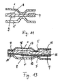
- Fig. 12 shows a section along the line I-I of Fig. 1 of an additional Embodiment.
- Fig. 13 shows a section along the line I-I of Fig. 1 of another Embodiment.
- the cylinder head gasket shown in detail in Fig. 1 in plan view comprises an elastic cover plate 1, usually made of spring steel, that with a series of adjacent to each other, each by a narrow web separate combustion chamber openings 2 corresponding to the Combustion chambers of an internal combustion engine and also with fluid passage openings 3 for cooling water or oil and screw openings 4 for screws is provided for bracing the cylinder block and cylinder head Internal combustion engine can be used.
- the cover plate 1 is provided with beads 5, that by far leaving a straight sheet metal section 6 in the edge area the combustion chamber opening 2 are arranged. Around the remaining openings 3, 4 seals are also not shown here, such as half beads or caterpillars rubber-elastic material provided.
- Deformation limiter 7 is provided. Instead of or together with it furthermore an outer deformation limiter 8 is provided, which is in relation to the Bead 5 on the side of the bead 5 facing away from the combustion chamber opening 2 located. Both deformation limiters 7, 8 are on the side of the Cover plate 1, to which the bead 5 is curved to limit its travel can.
- the one or more deformation limiters 7, 8 can be on the cover plate 1 or be arranged on a separate carrier or folded sheet 9 or 10, cf. Fig. 2 to 4, a second, elastic, corrugated cover sheet 1 'also being provided can and then preferably the deformation limiter 7 or 8 with respect to the mediated two mirror-symmetrically arranged cover plates 1, 1 '. If the deformation limiter 7 or 8 is made of metal, it can be welded on. But it can also be made of a highly filled plastic exist and be applied for example by screen printing. He can too applied by other methods such as plasma spraying or further molded be, cf. Fig. 10.
- the Deformation limiter 7 or 8 has a constant height, one according to the screw spacing continuous, by even tightened screws generated on the cylinder head gasket so clamped exerted pressure decrease (shown in dashed lines) from a screw to another to the middle area between two adjacent screws, which here the corners of a square are arranged. 5 considers accordingly the area from the center of the web (0 °) between two combustion chamber openings 2 to line I-I (90 °). The component rigidity (shown in solid lines) is in contrast, the largest and falls in the area of the screw passage opening 4 towards the intermediate screw area.
- Fig. 6 is the temperature expansion for that shown in Fig. 5 Area shown. Obviously this is the largest in the area of the footbridge, especially this is thin and the heat dissipation from this area compared to others Areas is relatively bad. This curve is also characterized by colder areas adjacent to cooling water channels affected accordingly. This is not here considered.
- Fig. 7 is a height profile of the deformation limiter 7 or 8 for the same area, as viewed in FIGS. 5 and 6, on the one hand for Compensation for component rigidity changes (solid) and on the other hand shown to compensate for the temperature expansion (dashed).
- the actual height profile of the Deformation limiter 7 or 8 essentially corresponds to one Mid-range between increase in pressure due to thermal expansion and Pressure reduction due to component stiffness (dash-dotted).
- the cylinder head gasket shown is one for one Internal combustion engine with cylinder liners 11, in corresponding holes of a cylinder block 12 are used and form the combustion chambers. This can e.g. around a cylinder block 12 made of an aluminum alloy and around Act cylinder liners 11 from gray cast iron. In the area between two neighboring combustion chambers run in the illustrated embodiment Bead 5 together into a common bead. The outer Deformation limiter 8 surround the beads 5 like glasses.
- a "radial" height profile can advantageously also be used here be provided by the depending on the component rigidity and temperature expansion inner deformation limiter 7 higher or lower than or equal to (radial to the combustion chamber axis or viewed in the longitudinal direction of the internal combustion engine) how the outer deformation limiter 8 can be designed.
- the fatigue strength of the deformation limiter 7 or 8 is increased and the edge pressure are kept low, with a slight crown or Chamfer the deformation limiter 7 or 8 radially outward this additionally supported.
- the Deformation limiter 7 formed as a separate ring, which in a corresponding Opening of the carrier plate 9 inserted and with this, for example Welding is connected.
- the carrier plate is 9 on the combustion chamber side with a cranked section 16 and on the Side of the bead 5 facing away from the combustion chamber with an approximately trapezoidal bead 17 provided.
- the section 16 and the bead 17 each form a bead 5 concentric surface 18, 18 ', the corresponding with a height profile in essentially corresponding to a middle range between increasing the pressure due to thermal expansion and lowering of the pressure due to component stiffness is provided and each with a deformation limiter 7 or 8 constant Interact height.
- the invention is also applicable to cylinder head gaskets, which are only one Have combustion chamber opening.
Landscapes
- Engineering & Computer Science (AREA)
- General Engineering & Computer Science (AREA)
- Mechanical Engineering (AREA)
- Chemical & Material Sciences (AREA)
- Combustion & Propulsion (AREA)
- Gasket Seals (AREA)
Abstract
Description
Claims (19)
- Metallische Zylinderkopfdichtung für eine einen benachbarte Brennkammern aufweisenden Zylinderblock und einen damit durch Schrauben verbundenen Zylinderkopf aufweisenden Brennkraftmaschine, mit wenigstens einer Blechlage (1) aus elastischem Metall, die mit einer oder mehreren Brennkammeröffnungen (2) entsprechend den Brennkammern der Brennkraftmaschine sowie mit Fluid- und Schraubendurchtrittsöffnungen (3, 4) versehen ist, wobei um jede Brennkammeröffnung (2) herum mit Abstand zu dieser unter Belassung eines geraden Blechabschnitts (6) im Öffnungsrandbereich eine Sicke (5) vorgesehen ist, deren Federweg durch einen sich konzentrisch zur Sicke (5) erstreckenden Verformungsbegrenzer (7, 8) begrenzt ist, wobei der Verformungsbegrenzer (7, 8) entsprechend der in bestimmten Bereichen aufgrund verminderter Bauteilsteifigkeit von Zylinderblock und Zylinderkopf im eingespannten Zustand der Zylinderkopfdichtung zu erwartenden Preßdruckerniedrigungen höhenund/oder breitenprofiliert ist, dadurch gekennzeichnet, daß bei der Höhenund/oder Breitenprofilierung des Verformungsbegrenzers (7, 8) zusätzlich die Preßdruckerhöhung infolge durch die Betriebstemperatur der Brennkraftmaschine zu erwartender Wärmedehnungen derart berücksichtigt ist, daß die Profilierung im wesentlichen entsprechend einem Mittelbereich zwischen Preßdruckerhöhung durch Wärmedehnungen und Preßdruckerniedrigung durch Bauteilsteifigkeiten ausgebildet ist oder daß der Verformungsbegrenzer (7, 8) eine gleichbleibende Höhe aufweist und ein Trägerblech (9) mit einer Höhenprofilierung versehen ist, so daß sich insgesamt eine Profilierung im wesentlichen entsprechend einem Mittelbereich zwischen Preßdruckerhöhung durch Wärmedehnungen und Preßdruckerniedrigung durch Bauteilsteifigkeiten ergibt, wobei der Verformungsbegrenzer (7, 8) im Bereich der Höhenprofilierung des Trägerblechs (9) angeordnet ist.
- Zylinderkopfdichtung nach Anspruch 1, dadurch gekennzeichnet, daß die Höhenprofilierung der Verformungsbegrenzer (7, 8) geprägt ist.
- Zylinderkopfdichtung nach Anspruch 1 oder 2, dadurch gekennzeichnet, daß die Höhe des Verformungsbegrenzers (7, 8) im Stegbereich zwischen zwei benachbarten Brennkammeröffnungen (2) gegenüber der Höhe im Bereich von benachbarten Schraubendurchtrittsöffnungen (4) erniedrigt ist.
- Zylinderkopfdichtung nach einem der Ansprüche 1 bis 3, dadurch gekennzeichnet, daß auf beiden Seiten der jeweiligen Sicke (5) ein Verformungsbegrenzer (7, 8) angeordnet ist.
- Zylinderkopfdichtung nach Anspruch 4, dadurch gekennzeichnet, daß der innere Verformungsbegrenzer (7) höher als der äußere Verformungsbegrenzer (8) ist.
- Zylinderkopfdichtung nach Anspruch 4, dadurch gekennzeichnet, daß der innere Verformungsbegrenzer (7) gleich hoch wie der äußere Verformungsbegrenzer (8) ist.
- Zylinderkopfdichtung nach Anspruch 4, dadurch gekennzeichnet, daß der innere Verformungsbegrenzer (7) niedriger als der äußere Verformungsbegrenzer (8) ist.
- Zylinderkopfdichtung nach einem der Ansprüche 1 bis 3, dadurch gekennzeichnet, daß nur ein innerer oder ein äußerer Verformungsbegrenzer (7, 8) für jede der Sicken (5) vorgesehen ist.
- Zylinderkopfdichtung nach einem der Ansprüche 1 bis 8, dadurch gekennzeichnet, daß der jeweilige Verformungsbegrenzer (7, 8) an einem Ring (13) oder Trägerblech (9) angestaucht ist.
- Zylinderkopfdichtung nach einem der Ansprüche 1 bis 8, dadurch gekennzeichnet, daß der jeweilige Verformungsbegrenzer (7, 8) als separater Ring bzw. Ringabschnitt ausgebildet ist.
- Zylinderkopfdichtung nach einem der Ansprüche 1 bis 10, dadurch gekennzeichnet, daß zwei gesickte Deckbleche (1, 1') vorgesehen sind, die spiegelsymmetrisch zueinander mit den Sickenscheiteln einander zugewandt angeordnet sind, zwischen denen sich die Verformungsbegrenzer (7, 8), gegebenenfalls an einem separaten Trägerblech (9), befinden.
- Metallische Zylinderkopfdichtung für eine einen benachbarte Brennkammern mit Zylinderlaufbuchsen (11) aufweisenden Zylinderblock (12) und einen damit durch Schrauben verbundenen Zylinderkopf aufweisenden Brennkraftmaschine, mit wenigstens einem Deckblech (1, 1') aus elastischem Metall und einem Trägerblech (9), die mit einer oder mehreren Brennkammeröffnungen (2) entsprechend den Brennkammern der Brennkraftmaschine sowie mit Fluid- und Schraubendurchtrittsöffnungen (3, 4) versehen sind, wobei das wenigstens eine Deckblech (1, 1') um jede Brennkammeröffnung (2) herum mit Abstand zu dieser unter Belassung eines geraden Blechabschnitts (6) im Öffnungsrandbereich eine Sicke (5) aufweist, deren Federweg durch einen sich konzentrisch zur Sicke (5) auf deren Außenseite erstreckenden, von dem Trägerblech (9) getragenen, äußeren Verformungsbegrenzer (8) begrenzt ist, wobei der äußere Verformungsbegrenzer (8) entsprechend der in bestimmten Bereichen aufgrund verminderter Bauteilsteifigkeit von Zylinderblock und Zylinderkopf im eingespannten Zustand der Zylinderkopfdichtung zu erwartenden Preßdruckerniedrigungen höhen- und/oder breitenprofiliert ist, dadurch gekennzeichnet, daß die Sicken (7) in einem Abstand zum Brennkammerrand angeordnet sind, so daß sie sich auf dem Zylinderblock (12) benachbart zu den Zylinderlaufbuchsen (11) abstützen, und daß auf der Innenseite der jeweiligen Sicke (5) ein innerer, vom Trägerblech (9) getragener, bezüglich der Bauteilsteifigkeit breiten- und/oder höhenprofilierter Verformungsbegrenzer (7) vorgesehen ist und bei der Höhen- und/oder Breitenprofilierung der Verformungsbegrenzers (7, 8) zusätzlich die Preßdruckerhöhung infolge durch die Betriebstemperatur der Brennkraftmaschine zu erwartender Wärmedehnungen derart berücksichtigt ist, daß die Profilierung im wesentlichen entsprechend einem Mittelbereich zwischen Preßdruckerhöhung durch Wärmedehnungen und Preßdruckerniedrigung durch Bauteilsteifigkeiten ausgebildet ist, oder daß der Verformungsbegrenzer (7, 8) eine gleichbleibende Höhe aufweist und ein Trägerblech (9) mit einer Höhenprofilierung versehen ist, so daß sich insgesamt eine Profilierung im wesentlichen entsprechend einem Mittelbereich zwischen Preßdruckerhöhung durch Wärmedehnungen und Preßdruckerniedrigung durch Bauteilsteifigkeiten ergibt, wobei der Verformungsbegrenzer (7, 8) im Bereich der Höhenprofilierung des Trägerblechs (9) angeordnet ist.
- Zylinderkopfdichtung nach Anspruch 12, dadurch gekennzeichnet, daß die Höhenprofilierung der Verformungsbegrenzer (7, 8) geprägt ist.
- Zylinderkopfdichtung nach Anspruch 12 oder 13, dadurch gekennzeichnet, daß die Höhe der Verformungsbegrenzer (7, 8) im Stegbereich zwischen zwei benachbarten Brennkammeröffnungen (2) gegenüber der Höhe im Bereich von benachbarten Schraubendurchtrittsöffnungen (4) erniedrigt ist.
- Zylinderkopfdichtung nach einem der Ansprüche 12 bis 14, dadurch gekennzeichnet, daß der innere Verformungsbegrenzer (7) höher als der äußere Verformungsbegrenzer (8) ist.
- Zylinderkopfdichtung nach einem der Ansprüche 12 bis 14, dadurch gekennzeichnet, daß der innere Verformungsbegrenzer (7) gleich hoch wie der äußere Verformungsbegrenzer (8) ist.
- Zylinderkopfdichtung nach einem der Ansprüche 12 bis 14, dadurch gekennzeichnet, daß der innere Verformungsbegrenzer (7) niedriger als der äußere Verformungsbegrenzer (8) ist.
- Zylinderkopfdichtung nach einem der Ansprüche 12 bis 17, dadurch gekennzeichnet, daß der jeweilige Verformungsbegrenzer (7, 8) an einem Ring (13) oder Trägerblech (9) angestaucht ist.
- Zylinderkopfdichtung nach einem der Ansprüche 12 bis 18, dadurch gekennzeichnet, daß der jeweilige Verformungsbegrenzer (7, 8) als separater Ring bzw. Ringabschnitt ausgebildet ist.
Priority Applications (2)
| Application Number | Priority Date | Filing Date | Title |
|---|---|---|---|
| DE20221256U DE20221256U1 (de) | 2001-04-05 | 2002-03-21 | Zylinderkopfdichtung |
| EP05010444.7A EP1577590B1 (de) | 2001-04-05 | 2002-03-21 | Zylinderkopfdichtung |
Applications Claiming Priority (2)
| Application Number | Priority Date | Filing Date | Title |
|---|---|---|---|
| DE10117178A DE10117178B4 (de) | 2001-04-05 | 2001-04-05 | Zylinderkopfdichtung |
| DE10117178 | 2001-04-05 |
Related Child Applications (1)
| Application Number | Title | Priority Date | Filing Date |
|---|---|---|---|
| EP05010444.7A Division EP1577590B1 (de) | 2001-04-05 | 2002-03-21 | Zylinderkopfdichtung |
Publications (3)
| Publication Number | Publication Date |
|---|---|
| EP1248024A2 true EP1248024A2 (de) | 2002-10-09 |
| EP1248024A3 EP1248024A3 (de) | 2004-10-06 |
| EP1248024B1 EP1248024B1 (de) | 2006-07-05 |
Family
ID=7680627
Family Applications (2)
| Application Number | Title | Priority Date | Filing Date |
|---|---|---|---|
| EP05010444.7A Expired - Lifetime EP1577590B1 (de) | 2001-04-05 | 2002-03-21 | Zylinderkopfdichtung |
| EP02006320A Expired - Lifetime EP1248024B1 (de) | 2001-04-05 | 2002-03-21 | Zylinderkopfdichtung |
Family Applications Before (1)
| Application Number | Title | Priority Date | Filing Date |
|---|---|---|---|
| EP05010444.7A Expired - Lifetime EP1577590B1 (de) | 2001-04-05 | 2002-03-21 | Zylinderkopfdichtung |
Country Status (4)
| Country | Link |
|---|---|
| US (1) | US7997585B2 (de) |
| EP (2) | EP1577590B1 (de) |
| DE (3) | DE10117178B4 (de) |
| ES (1) | ES2266332T3 (de) |
Cited By (3)
| Publication number | Priority date | Publication date | Assignee | Title |
|---|---|---|---|---|
| CN102207041A (zh) * | 2011-08-10 | 2011-10-05 | 长城汽车股份有限公司 | 可避免冲蚀的汽油机气缸 |
| CN102562354A (zh) * | 2010-12-10 | 2012-07-11 | 丰田合成株式会社 | 可变压缩比发动机用密封罩 |
| EP4343178A4 (de) * | 2021-05-19 | 2024-10-30 | Kabushiki Kaisha Toyota Jidoshokki | Dichtung |
Families Citing this family (19)
| Publication number | Priority date | Publication date | Assignee | Title |
|---|---|---|---|---|
| DE102004029351B4 (de) * | 2004-06-17 | 2008-09-25 | Reinz-Dichtungs-Gmbh | Metallische Zylinderkopfdichtung für einen Verbrennungsmotor mit Laufbuchse |
| DE102005013416A1 (de) * | 2005-03-23 | 2006-09-28 | Federal-Mogul Sealing Systems Gmbh | Flachdichtung |
| DE102005013417B4 (de) * | 2005-03-23 | 2008-05-29 | Federal-Mogul Sealing Systems Gmbh | Flachdichtung |
| DE102005019689A1 (de) * | 2005-04-28 | 2006-11-16 | Elringklinger Ag | Flachdichtung, insbesondere Zylinderkopfdichtung |
| JP4875356B2 (ja) * | 2005-10-24 | 2012-02-15 | 日本メタルガスケット株式会社 | ガスケット |
| WO2008084718A1 (ja) * | 2007-01-12 | 2008-07-17 | Nippon Gasket Co., Ltd. | 金属ガスケット |
| US8632077B2 (en) | 2008-02-13 | 2014-01-21 | Federal-Mogul Corporation | Multilayer static gasket with bead compression limiter |
| US8960681B2 (en) * | 2008-07-17 | 2015-02-24 | Nippon Gasket Co., Ltd. | Cylinder head gasket |
| US20110127729A1 (en) * | 2008-09-18 | 2011-06-02 | Yasumaro Takeda | Cylinder head gasket |
| DE102009008791A1 (de) * | 2009-02-13 | 2010-09-16 | Federal-Mogul Sealing Systems Gmbh | Flachdichtungen mit zusätzlichem Abdichtelement |
| CN102549317B (zh) * | 2009-06-24 | 2014-11-05 | 费德罗-莫格尔公司 | 汽缸盖垫片 |
| JP5061204B2 (ja) * | 2010-01-07 | 2012-10-31 | 株式会社豊田自動織機 | シリンダヘッドガスケット |
| DE102011002872B4 (de) * | 2011-01-19 | 2018-11-15 | Federal-Mogul Sealing Systems Gmbh | Verfahren zur Herstellung einer Zylinderkopfdichtung und dadurch hergestellte Zylinderkopfdichtung |
| CN103403411B (zh) | 2011-02-01 | 2015-07-29 | 费德罗-莫格尔公司 | 具有次压缩限制器的多层静态垫片 |
| US9476382B2 (en) * | 2012-08-10 | 2016-10-25 | Dana Automotive Systems Group, Llc | Multi-layered gasket |
| DE102013104269A1 (de) * | 2013-04-26 | 2014-10-30 | Elringklinger Ag | Metallische Flachdichtung sowie Verfahren zu deren Herstellung |
| DE102014108131A1 (de) * | 2014-06-10 | 2015-12-17 | Elringklinger Ag | Zylinderkopfdichtung |
| US10359003B2 (en) * | 2014-06-23 | 2019-07-23 | Tenneco Inc. | Cylinder head gasket with compression limiter and full bead loading |
| US10119494B2 (en) | 2015-07-28 | 2018-11-06 | Tenneco Inc. | Multi-layer gasket assembly |
Citations (4)
| Publication number | Priority date | Publication date | Assignee | Title |
|---|---|---|---|---|
| EP0230804B1 (de) | 1985-12-27 | 1990-06-13 | Nihon Metal Gasket Kabushiki Kaisha | Metalldichtung |
| EP0306766B1 (de) | 1987-09-05 | 1992-04-08 | Nihon Metal Gasket Kabushiki Kaisha | Laminierte Metalldichtung |
| DE19513360C1 (de) | 1995-04-08 | 1996-06-27 | Elringklinger Gmbh | Metallische Zylinderkopfdichtung |
| EP0740092A1 (de) | 1995-04-26 | 1996-10-30 | Elring Klinger GmbH | Metallische Zylinderkopfdichtung |
Family Cites Families (13)
| Publication number | Priority date | Publication date | Assignee | Title |
|---|---|---|---|---|
| JPS62155375A (ja) * | 1985-12-27 | 1987-07-10 | Nippon Metal Gasket Kk | 金属ガスケツト |
| DE4222338C2 (de) * | 1992-07-08 | 1994-04-21 | Goetze Ag | Flachdichtung |
| US5618049A (en) * | 1993-06-04 | 1997-04-08 | Japan Metal Gasket Co., Ltd. | Metallic gasket |
| JP3489755B2 (ja) * | 1994-08-05 | 2004-01-26 | 日本ガスケット株式会社 | 金属製ガスケット |
| DE59604933D1 (de) * | 1995-04-08 | 2000-05-18 | Elringklinger Gmbh | Metallische Zylinderkopfdichtung |
| DE19611092C2 (de) * | 1996-03-21 | 2001-04-26 | Elringklinger Gmbh | Verfahren zum Aufbringen einer Überhöhung auf eine Metallage einer Zylinderkopfdichtung und Zylinderkopfdichtung |
| JP2929485B2 (ja) * | 1996-05-22 | 1999-08-03 | 石川ガスケット株式会社 | 金属積層形ガスケット |
| US5957463A (en) * | 1997-03-14 | 1999-09-28 | Ishikawa Gasket Co., Ltd. | Metal laminate gasket with irregular size seal ring |
| JPH112324A (ja) * | 1997-06-16 | 1999-01-06 | Ishikawa Gasket Kk | ヘッドガスケット |
| DE19844570C1 (de) * | 1998-09-29 | 2000-04-13 | Daimler Chrysler Ag | Zylinderkopfdichtung |
| JP3419447B2 (ja) * | 2000-08-07 | 2003-06-23 | 石川ガスケット株式会社 | ヘッドガスケット |
| US7017918B2 (en) * | 2001-10-25 | 2006-03-28 | Federal-Mogul World Wide, Inc. | Combustion stopper seal |
| US6957815B1 (en) * | 2002-04-23 | 2005-10-25 | Dana Corporation | MLS gasket with epoxy bead stopper layer |
-
2001
- 2001-04-05 DE DE10117178A patent/DE10117178B4/de not_active Expired - Fee Related
-
2002
- 2002-03-21 EP EP05010444.7A patent/EP1577590B1/de not_active Expired - Lifetime
- 2002-03-21 ES ES02006320T patent/ES2266332T3/es not_active Expired - Lifetime
- 2002-03-21 DE DE20221256U patent/DE20221256U1/de not_active Expired - Lifetime
- 2002-03-21 EP EP02006320A patent/EP1248024B1/de not_active Expired - Lifetime
- 2002-03-21 DE DE50207418T patent/DE50207418D1/de not_active Expired - Lifetime
- 2002-04-03 US US10/116,317 patent/US7997585B2/en not_active Expired - Fee Related
Patent Citations (4)
| Publication number | Priority date | Publication date | Assignee | Title |
|---|---|---|---|---|
| EP0230804B1 (de) | 1985-12-27 | 1990-06-13 | Nihon Metal Gasket Kabushiki Kaisha | Metalldichtung |
| EP0306766B1 (de) | 1987-09-05 | 1992-04-08 | Nihon Metal Gasket Kabushiki Kaisha | Laminierte Metalldichtung |
| DE19513360C1 (de) | 1995-04-08 | 1996-06-27 | Elringklinger Gmbh | Metallische Zylinderkopfdichtung |
| EP0740092A1 (de) | 1995-04-26 | 1996-10-30 | Elring Klinger GmbH | Metallische Zylinderkopfdichtung |
Cited By (4)
| Publication number | Priority date | Publication date | Assignee | Title |
|---|---|---|---|---|
| CN102562354A (zh) * | 2010-12-10 | 2012-07-11 | 丰田合成株式会社 | 可变压缩比发动机用密封罩 |
| CN102207041A (zh) * | 2011-08-10 | 2011-10-05 | 长城汽车股份有限公司 | 可避免冲蚀的汽油机气缸 |
| EP4343178A4 (de) * | 2021-05-19 | 2024-10-30 | Kabushiki Kaisha Toyota Jidoshokki | Dichtung |
| US12292113B2 (en) | 2021-05-19 | 2025-05-06 | Kabushiki Kaisha Toyota Jidoshokki | Gasket |
Also Published As
| Publication number | Publication date |
|---|---|
| DE10117178B4 (de) | 2006-11-09 |
| DE20221256U1 (de) | 2005-08-18 |
| EP1577590B1 (de) | 2017-11-15 |
| DE50207418D1 (de) | 2006-08-17 |
| ES2266332T3 (es) | 2007-03-01 |
| DE10117178A1 (de) | 2002-10-17 |
| US7997585B2 (en) | 2011-08-16 |
| EP1577590A1 (de) | 2005-09-21 |
| US20020180161A1 (en) | 2002-12-05 |
| EP1248024B1 (de) | 2006-07-05 |
| EP1248024A3 (de) | 2004-10-06 |
Similar Documents
| Publication | Publication Date | Title |
|---|---|---|
| EP1248024B1 (de) | Zylinderkopfdichtung | |
| DE19829656B4 (de) | Metalldichtung | |
| DE60108672T2 (de) | Zylinderkopfdichtung | |
| EP1985898A1 (de) | Metallische Flachdichtung | |
| DE69726061T2 (de) | Metalldichtung mit einer Ringdichtung | |
| EP0816723B1 (de) | Metallische Flachdichtung | |
| EP1327799A2 (de) | Zylinderkopfdichtung zum Ausgleich von lokalen Absenkungen im Bereich des Verpressungsbegrenzers | |
| DE102004026395A1 (de) | Zylinderkopfdichtung | |
| DE19611092C2 (de) | Verfahren zum Aufbringen einer Überhöhung auf eine Metallage einer Zylinderkopfdichtung und Zylinderkopfdichtung | |
| DE10324667A1 (de) | Zylinderkopfdichtung | |
| DE102016002582A1 (de) | Flachdichtung, insbesondere Zylinderkopfdichtung | |
| EP1340010B2 (de) | Flachdichtung für eine kolbenkraft- oder arbeitsmaschine | |
| DE19513361C1 (de) | Metallische Zylinderkopfdichtung | |
| EP3099962B1 (de) | Zylinderkopfdichtung sowie ein eine solche umfassendes abdichtsystem | |
| DE19725986A1 (de) | Metallische Zylinderkopfdichtung | |
| EP0939256A1 (de) | Dichtungssystem | |
| DE19512650C2 (de) | Zylinderkopfdichtung für eine Brennkraftmaschine | |
| DE102004054712B4 (de) | Zylinderkopfdichtung | |
| DE19822143C1 (de) | Zylinderkopfdichtung | |
| WO2019038319A1 (de) | Zylinderkopfdichtung | |
| EP3380760B1 (de) | Flachdichtung sowie eine flachdichtung enthaltender dichtverband | |
| EP0780603A1 (de) | Zylinderkopfdichtung | |
| EP1271016B1 (de) | Flachdichtung und deren Herstellungsverfahren | |
| EP0780561B2 (de) | Zylinderkopfdichtung | |
| DE19548574A1 (de) | Metallische Flachdichtung |
Legal Events
| Date | Code | Title | Description |
|---|---|---|---|
| PUAI | Public reference made under article 153(3) epc to a published international application that has entered the european phase |
Free format text: ORIGINAL CODE: 0009012 |
|
| AK | Designated contracting states |
Kind code of ref document: A2 Designated state(s): AT BE CH CY DE DK ES FI FR GB GR IE IT LI LU MC NL PT SE TR |
|
| AX | Request for extension of the european patent |
Free format text: AL;LT;LV;MK;RO;SI |
|
| PUAL | Search report despatched |
Free format text: ORIGINAL CODE: 0009013 |
|
| AK | Designated contracting states |
Kind code of ref document: A3 Designated state(s): AT BE CH CY DE DK ES FI FR GB GR IE IT LI LU MC NL PT SE TR |
|
| AX | Request for extension of the european patent |
Extension state: AL LT LV MK RO SI |
|
| 17P | Request for examination filed |
Effective date: 20050202 |
|
| GRAP | Despatch of communication of intention to grant a patent |
Free format text: ORIGINAL CODE: EPIDOSNIGR1 |
|
| AKX | Designation fees paid |
Designated state(s): DE ES FR GB IT |
|
| RBV | Designated contracting states (corrected) |
Designated state(s): DE ES FR GB IT |
|
| GRAS | Grant fee paid |
Free format text: ORIGINAL CODE: EPIDOSNIGR3 |
|
| RAP1 | Party data changed (applicant data changed or rights of an application transferred) |
Owner name: ELRINGKLINGER AG |
|
| GRAA | (expected) grant |
Free format text: ORIGINAL CODE: 0009210 |
|
| AK | Designated contracting states |
Kind code of ref document: B1 Designated state(s): DE ES FR GB IT |
|
| PG25 | Lapsed in a contracting state [announced via postgrant information from national office to epo] |
Ref country code: IT Free format text: LAPSE BECAUSE OF FAILURE TO SUBMIT A TRANSLATION OF THE DESCRIPTION OR TO PAY THE FEE WITHIN THE PRESCRIBED TIME-LIMIT;WARNING: LAPSES OF ITALIAN PATENTS WITH EFFECTIVE DATE BEFORE 2007 MAY HAVE OCCURRED AT ANY TIME BEFORE 2007. THE CORRECT EFFECTIVE DATE MAY BE DIFFERENT FROM THE ONE RECORDED. Effective date: 20060705 |
|
| REG | Reference to a national code |
Ref country code: GB Ref legal event code: FG4D Free format text: NOT ENGLISH |
|
| REF | Corresponds to: |
Ref document number: 50207418 Country of ref document: DE Date of ref document: 20060817 Kind code of ref document: P |
|
| GBT | Gb: translation of ep patent filed (gb section 77(6)(a)/1977) |
Effective date: 20061009 |
|
| ET | Fr: translation filed | ||
| REG | Reference to a national code |
Ref country code: ES Ref legal event code: FG2A Ref document number: 2266332 Country of ref document: ES Kind code of ref document: T3 |
|
| PLBI | Opposition filed |
Free format text: ORIGINAL CODE: 0009260 |
|
| 26 | Opposition filed |
Opponent name: STE GESELLSCHAFT FUER DICHTUNGSTECHNIK MBH Effective date: 20070402 |
|
| PLAX | Notice of opposition and request to file observation + time limit sent |
Free format text: ORIGINAL CODE: EPIDOSNOBS2 |
|
| PLBI | Opposition filed |
Free format text: ORIGINAL CODE: 0009260 |
|
| 26 | Opposition filed |
Opponent name: FEDERAL MOGUL SEALING SYSTEMS GMBH Effective date: 20070403 Opponent name: STE GESELLSCHAFT FUER DICHTUNGSTECHNIK MBH Effective date: 20070402 |
|
| PLBB | Reply of patent proprietor to notice(s) of opposition received |
Free format text: ORIGINAL CODE: EPIDOSNOBS3 |
|
| PGFP | Annual fee paid to national office [announced via postgrant information from national office to epo] |
Ref country code: ES Payment date: 20090324 Year of fee payment: 8 |
|
| PGFP | Annual fee paid to national office [announced via postgrant information from national office to epo] |
Ref country code: GB Payment date: 20090325 Year of fee payment: 8 |
|
| PGFP | Annual fee paid to national office [announced via postgrant information from national office to epo] |
Ref country code: IT Payment date: 20090321 Year of fee payment: 8 |
|
| GBPC | Gb: european patent ceased through non-payment of renewal fee |
Effective date: 20100321 |
|
| PLCK | Communication despatched that opposition was rejected |
Free format text: ORIGINAL CODE: EPIDOSNREJ1 |
|
| PG25 | Lapsed in a contracting state [announced via postgrant information from national office to epo] |
Ref country code: GB Free format text: LAPSE BECAUSE OF NON-PAYMENT OF DUE FEES Effective date: 20100321 Ref country code: IT Free format text: LAPSE BECAUSE OF NON-PAYMENT OF DUE FEES Effective date: 20100321 |
|
| PLBN | Opposition rejected |
Free format text: ORIGINAL CODE: 0009273 |
|
| STAA | Information on the status of an ep patent application or granted ep patent |
Free format text: STATUS: OPPOSITION REJECTED |
|
| 27O | Opposition rejected |
Effective date: 20101203 |
|
| REG | Reference to a national code |
Ref country code: ES Ref legal event code: FD2A Effective date: 20111118 |
|
| PG25 | Lapsed in a contracting state [announced via postgrant information from national office to epo] |
Ref country code: ES Free format text: LAPSE BECAUSE OF NON-PAYMENT OF DUE FEES Effective date: 20100322 |
|
| REG | Reference to a national code |
Ref country code: FR Ref legal event code: PLFP Year of fee payment: 15 |
|
| PGFP | Annual fee paid to national office [announced via postgrant information from national office to epo] |
Ref country code: FR Payment date: 20160322 Year of fee payment: 15 |
|
| REG | Reference to a national code |
Ref country code: FR Ref legal event code: ST Effective date: 20171130 |
|
| PG25 | Lapsed in a contracting state [announced via postgrant information from national office to epo] |
Ref country code: FR Free format text: LAPSE BECAUSE OF NON-PAYMENT OF DUE FEES Effective date: 20170331 |
|
| PGFP | Annual fee paid to national office [announced via postgrant information from national office to epo] |
Ref country code: DE Payment date: 20200324 Year of fee payment: 19 |
|
| REG | Reference to a national code |
Ref country code: DE Ref legal event code: R119 Ref document number: 50207418 Country of ref document: DE |
|
| PG25 | Lapsed in a contracting state [announced via postgrant information from national office to epo] |
Ref country code: DE Free format text: LAPSE BECAUSE OF NON-PAYMENT OF DUE FEES Effective date: 20211001 |