EP1247931A2 - Schliessfolgeregler - Google Patents
Schliessfolgeregler Download PDFInfo
- Publication number
- EP1247931A2 EP1247931A2 EP02003435A EP02003435A EP1247931A2 EP 1247931 A2 EP1247931 A2 EP 1247931A2 EP 02003435 A EP02003435 A EP 02003435A EP 02003435 A EP02003435 A EP 02003435A EP 1247931 A2 EP1247931 A2 EP 1247931A2
- Authority
- EP
- European Patent Office
- Prior art keywords
- leaf
- push rod
- sequence controller
- locking
- controller according
- Prior art date
- Legal status (The legal status is an assumption and is not a legal conclusion. Google has not performed a legal analysis and makes no representation as to the accuracy of the status listed.)
- Granted
Links
- 230000007246 mechanism Effects 0.000 claims abstract description 6
- 238000005096 rolling process Methods 0.000 claims description 2
- 238000012423 maintenance Methods 0.000 description 3
- 230000008439 repair process Effects 0.000 description 3
- 230000008901 benefit Effects 0.000 description 2
- 238000010276 construction Methods 0.000 description 2
- 238000005553 drilling Methods 0.000 description 2
- 238000003860 storage Methods 0.000 description 2
- 230000006978 adaptation Effects 0.000 description 1
- 238000011161 development Methods 0.000 description 1
- 230000018109 developmental process Effects 0.000 description 1
- 238000007373 indentation Methods 0.000 description 1
- 238000004519 manufacturing process Methods 0.000 description 1
- 238000000034 method Methods 0.000 description 1
- 238000012986 modification Methods 0.000 description 1
- 230000004048 modification Effects 0.000 description 1
- 230000036316 preload Effects 0.000 description 1
- 230000008569 process Effects 0.000 description 1
- 230000000284 resting effect Effects 0.000 description 1
- 238000009420 retrofitting Methods 0.000 description 1
- 238000012549 training Methods 0.000 description 1
- 230000007704 transition Effects 0.000 description 1
Images




Classifications
-
- E—FIXED CONSTRUCTIONS
- E05—LOCKS; KEYS; WINDOW OR DOOR FITTINGS; SAFES
- E05F—DEVICES FOR MOVING WINGS INTO OPEN OR CLOSED POSITION; CHECKS FOR WINGS; WING FITTINGS NOT OTHERWISE PROVIDED FOR, CONCERNED WITH THE FUNCTIONING OF THE WING
- E05F5/00—Braking devices, e.g. checks; Stops; Buffers
- E05F5/12—Braking devices, e.g. checks; Stops; Buffers specially for preventing the closing of a wing before another wing has been closed
-
- E—FIXED CONSTRUCTIONS
- E05—LOCKS; KEYS; WINDOW OR DOOR FITTINGS; SAFES
- E05C—BOLTS OR FASTENING DEVICES FOR WINGS, SPECIALLY FOR DOORS OR WINDOWS
- E05C7/00—Fastening devices specially adapted for two wings
- E05C7/04—Fastening devices specially adapted for two wings for wings which abut when closed
- E05C7/06—Fastening devices specially adapted for two wings for wings which abut when closed a fastening device for one wing being actuated or controlled by closing another wing
-
- E—FIXED CONSTRUCTIONS
- E05—LOCKS; KEYS; WINDOW OR DOOR FITTINGS; SAFES
- E05Y—INDEXING SCHEME ASSOCIATED WITH SUBCLASSES E05D AND E05F, RELATING TO CONSTRUCTION ELEMENTS, ELECTRIC CONTROL, POWER SUPPLY, POWER SIGNAL OR TRANSMISSION, USER INTERFACES, MOUNTING OR COUPLING, DETAILS, ACCESSORIES, AUXILIARY OPERATIONS NOT OTHERWISE PROVIDED FOR, APPLICATION THEREOF
- E05Y2201/00—Constructional elements; Accessories therefor
- E05Y2201/60—Suspension or transmission members; Accessories therefor
- E05Y2201/622—Suspension or transmission members elements
- E05Y2201/686—Rods, links
-
- E—FIXED CONSTRUCTIONS
- E05—LOCKS; KEYS; WINDOW OR DOOR FITTINGS; SAFES
- E05Y—INDEXING SCHEME ASSOCIATED WITH SUBCLASSES E05D AND E05F, RELATING TO CONSTRUCTION ELEMENTS, ELECTRIC CONTROL, POWER SUPPLY, POWER SIGNAL OR TRANSMISSION, USER INTERFACES, MOUNTING OR COUPLING, DETAILS, ACCESSORIES, AUXILIARY OPERATIONS NOT OTHERWISE PROVIDED FOR, APPLICATION THEREOF
- E05Y2900/00—Application of doors, windows, wings or fittings thereof
- E05Y2900/10—Application of doors, windows, wings or fittings thereof for buildings or parts thereof
- E05Y2900/13—Type of wing
- E05Y2900/132—Doors
- E05Y2900/134—Fire doors
Definitions
- the invention relates to a closing sequence controller for a self-closing, a door comprising a passive leaf and an active leaf, in particular a fire door, wherein the active leaf by means of a releasable from the passive leaf Locking mechanism can be determined.
- closing sequence controllers are used, which are always the ones for the aforementioned proper closing required sequence ensure the transitions of the two wings into the closed position.
- a certain order of closing movement of both door leaves is also therefore necessary to get the usually with a lock Only let the active leaf reach the closed position when the the door stop, usually the striking plate or the like having standing leaf is closed.
- DE 33 36 739 C2 discloses a closing sequence controller for a self-closing, a door comprising a passive and a moving wing, in particular Fire protection door, known, the door wing each with a swivel arm are connected to the door frame, the swivel arm of the active leaf can be ascertained by means of a locking member which can be released from the passive leaf.
- the end of the swivel arm of the active leaf is on the door frame side with a sliding guide attached to the door frame guided slider provided, which is lockable by the locking member.
- the Inactive leaf interacts with an axially adjustable thrust member that acts to release the locking of the slider on the locking member.
- the object of the present invention is therefore the above eliminate the disadvantages mentioned and a mechanical Closing sequence controller to create a secured closing sequence double-leaf door guaranteed, but with as few and as possible simply constructed components.
- Such a closing sequence controller can, for. B. be constructed so that within a basic body is used for the sliding guide at every necessary point which is then fixed at the required point. Consequently is an individual adjustment to the door sizes or to the locking behavior of the doors adjustable.
- Inside the body are in the longitudinal direction two parallel holes in which Push rods are introduced, each through the sliders of the Standing or moving leaf can be controlled. These are push rods formed so that they are spring-loaded and stops at their ends exhibit. Together with the push rods, the locking member works that z. B. is inserted within a recess in the base body.
- the Locking element is movably arranged within the recess. The Locking element is removed from its respective position by the push rods then pushed out when evasion of the locking member is possible.
- To allow the locking member to evade are located in the push rods indentations preferably in the form of a circumferential groove.
- the structure is simple and simple Components a closing sequence controller provided that a secured Guaranteed closing sequence.
- the construction also has the advantage that the entire closing sequence controller is very compact and can therefore be easily and conveniently installed and removed, e.g. B. at a repair or for maintenance purposes. Since it is made up of only a few and relatively small individual parts, is not just the storage of the whole Closing sequence controller, but also the provision of individual or Spare parts simple and uncomplicated and require little space. at The closing sequence controller can perform maintenance and repair work after the present invention because of its light weight also easily be installed or removed. Later retrofitting is also possible possible within the slide rail.
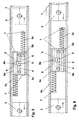
- FIG. 1 to 10 is the structure and operation of a closing sequence controller according to a first embodiment of the present invention shown.
- This closing sequence controller is particularly suitable for one Door with a moving leaf and a passive leaf (not in the figures shown) each connected to the door frame via a swivel arm are.
- the door frame side end of the swivel arm Inactive leaf with one in or on the door frame Slide guide 1 slidably guided leaf slide 2 provided.
- the end of the swivel arm of the active leaf is on the door frame side with one also slidably guided in the sliding guide 1 Provide active leaf slide 3.
- the active leaf, the passive leaf, the door frame and the two swivel arms are general state of the art and are therefore not described in detail here shown or explained.
- the closing sequence controller comprises a base body 4, which in the sliding guide 1 between the passive leaf slide 2 and the active leaf slide 3 is provided fixed.
- two are parallel and in Holes 5a, 6a for receiving which run in the longitudinal direction of the sliding guide 1 a passive leaf push rod 5 and a moving leaf push rod 6 introduced.
- the passive leaf push rod 5 and Active leaf push rod 6 displaceable in the longitudinal direction of the bores 5a, 6a, if they from the passive leaf slide 2 or from the Active leaf slider 3 are applied.
- the passive leaf push rod 5 and the active leaf push rod 6 each have at their ends Attacks 7 on.
- each of the two push rods 5, 6 each provided with a circumferential groove 5b, 6b. Both push rods 5, 6 are preferably each by a coil spring 5c, 6c in opposite Directions biased so that the passive leaf push rod 5 in the direction of the fixed leaf slide 2 and the active leaf push rod 6 are preloaded in the direction of the active leaf slide 3.
- Recess 8 provided in which a locking member 9 in the form of a rolling element, preferably a cylinder is arranged.
- the recess 8 is designed so that the locking member 9 in one direction can move transversely to the direction of movement of the push rods 5, 6.
- the locking member 9 dimensioned and arranged so that it either on one side or on the other side over the recess 8 protrudes and with the protruding part either in the hole 5a for the passive leaf push rod 5 or in the hole 6a for the Active leaf push rod 6 protrudes with the protruding part either in the circumferential groove 5b of the leaf push rod 5 or in the Circumferential groove 6b of the active leaf push rod 6 engages.
- the locking member is thus floating and embedded within the base body 4 controlled via the push rods 5, 6 by the sliders 2 and 3.
- Fig. 1 the position of the closing sequence controller is at the zero position of a door shown, in which both door leaves are closed.
- the distance x between the center of the circumferential groove 6b and the center of the Recess 8 or the locking member 9 ensures that the Active leaf slide 3 at the minimum open bracket and thus corresponds the path that the active leaf slide 3 to reach the Minimum open angle covered.
- the active leaf slide moves 3 to the left in Fig. 2. Due to the preload of the coil spring 6c, the active leaf push rod 6 follows the active leaf slide 3 long until it abuts the base body 4 with its stop 7. This state where the active leaf is opened and the passive leaf is closed is shown in Fig. 2.
- the active leaf can therefore be opened and opened as required be closed as long as the passive leaf is closed.
- the active leaf slide moves 3 against the active leaf push rod 6 and is in this Position held because the locking member 9 has no way in the circumferential groove 5b of the passive leaf push rod 5 and thus the Active leaf push rod 6 locked in the locked position.
- the passive leaf slide 2 is in turn able to push the passive leaf push rod 5 in to press their starting position since it is not in the resting position, is not prevented from moving by the locking member 9. Only when the passive leaf push rod 5 is in the starting position can the active leaf slider 3 or the spring force the locking member 9th press into the circumferential groove 5b of the standing flight push rod 5 and thus move the active leaf push rod 6 to its zero position and the passive leaf push rod 5 lock. This ensures a correct closing sequence.
- FIGS. 9 and 10 show a closing sequence controller, as already described above shown with an overload protection.
- Therefor is located within the base body 4 in the area of the passive leaf push rod 5 preferably in the area of the locking member 9 an additional Recess 10.
- the recess 10 is in its longitudinal extent limited laterally by the bores 5a, which merge into the recess 10.
- the width of the recess preferably extends in Direction towards the wall of the sliding guide 1.
- the active leaf slider 3 continues in the direction of the base body 4 pressed, so the active leaf push rod 6 with its outer circumference the locking member 9 against the outer circumference of the passive leaf push rod Press 5.
- this gives way the existing recess 10 from the side (see Figures 9 and 10). It is therefore a deliberate overpressure and therefore a closure of the active leaf in front of the passive leaf.
- the closing sequence controller is damaged if z. B. willfully pressed the active leaf in front of the passive leaf.
- the base body 4 is designed so that everyone required position within the sliding guide 1 inserted and fixed can be. This is an individual adaptation to the building situation given the door.
Landscapes
- Engineering & Computer Science (AREA)
- Mechanical Engineering (AREA)
- Power-Operated Mechanisms For Wings (AREA)
- Catalysts (AREA)
- Lasers (AREA)
- Catching Or Destruction (AREA)
- Air-Flow Control Members (AREA)
- Valve Device For Special Equipments (AREA)
- Lock And Its Accessories (AREA)
Abstract
Description
- der Sperrmechanismus weist mindestens eine axial bewegbare erste Schubstange und ein Sperrelement auf,
- zwischen der ersten Schubstange und dem Sperrelement ist ein bewegbares Sperrglied angeordnet, welches entweder nur eine Bewegung der ersten Schubstange oder nur eine Bewegung des weiteren Sperrelementes zulässt.
- Figur 1 bis 10:
- Den Aufbau und die Arbeitsweise eines erfindungsgemäßen Schließfolgereglers nach einer ersten Ausführungsform und
- Figur 11:
- eine zweite Ausführungsform des erfindungsgemäßen Schließfolgereglers.
- 1
- Gleitführung
- 2
- Standflügel-Gleitstück
- 3
- Gangflügel-Gleitstück
- 4
- Grundkörper
- 5
- Standflügel-Schubstange
- 5a
- Bohrung
- 5b
- Umfangsnut
- 5c
- Schraubenfeder
- 6
- Gangflügel-Schubstange
- 6a
- Bohrung
- 6b
- Umfangsnut
- 6c
- Schraubenfeder
- 7
- Anschläge
- 8
- Ausnehmung
- 9
- Sperrglied
- 10
- Ausnehmung
Claims (12)
- Schließfolgeregler für eine selbstschließende, einen Stand- und einen Gangflügel umfassende Tür, insbesondere Feuerschutztür, wobei der Gangflügel mittels eines vom Standflügel freigebbaren Sperrmechanismus feststellbar ist, gekennzeichnet durch folgende Merkmale:Der Sperrmechanismus weist mindestens eine axial bewegbare erste Schubstange (5) und ein Sperrelement (6) auf,zwischen der ersten Schubstange (5) und dem Sperrelement (6) ist ein bewegbares Sperrglied (9) angeordnet, welches im Normalbetrieb entweder nur eine Bewegung der ersten Schubstange (5) oder nur eine Bewegung des Sperrelementes (6) zulässt,es ist eine Überlastsicherung vorhanden.
- Schließfolgeregler nach Anspruch 1, dadurch gekennzeichnet, dass das Sperrelement (6) ebenfalls eine axial bewegbare Schubstange (6) ist, die parallel zur ersten Schubstange (5) angeordnet ist.
- Schließfolgeregler nach Anspruch 1 oder 2, dadurch gekennzeichnet, dass der Standflügel über einen Schwenkarm mit dem Türrahmen verbunden ist und das türrahmenseitige Ende des Schwenkarmes des Standflügels mit einem in einer am Türrahmen angebrachten Gleitführung (1) verschiebbar geführten Standflügel-Gleitstück (2) versehen ist.
- Schließfolgeregler nach einem der vorhergehenden Ansprüche, dadurch gekennzeichnet, dass der Gangflügel über einen Schwenkarm mit dem Türrahmen verbunden ist und das türrahmenseitige Ende des Schwenkarmes des Gangflügels mit einem ebenfalls in der Gleitführung (1) verschiebbar geführten Gangflügel-Gleitstück (3) versehen ist.
- Schließfolgeregler nach einem der vorhergehenden Ansprüche, dadurch gekennzeichnet, dass die beiden Schubstangen (5, 6) in zwei parallel verlaufenden Bohrungen (5a, 6a) eines Grundkörpers (4) axial verschieblich gelagert sind und der Grundkörper (4) in der Gleitführung (1) zwischen dem Standflügel-Gleitstück (2) und dem Gangflügel-Gleitstück (3) verschiebbar angeordnet und festsetzbar ist.
- Schließfolgeregler nach einem der vorhergehenden Ansprüche, dadurch gekennzeichnet, dass die eine Schubstange (5) vom Standflügel-Gleitstück (2) und die anderen Schubstange (6) vom Gangflügel-Gleitstück (3) beaufschlagbar ist.
- Schließfolgeregler nach einem der vorhergehenden Ansprüche, dadurch gekennzeichnet, dass die beiden Schubstangen (5, 6) in entgegengesetzten Richtungen vorzugsweise durch je eine Schraubenfeder (5c, 6c) federbelastet sind und sich jede Schraubenfeder (5c, 6c) mit ihrem einen Ende am Grundkörper (4) und mit ihrem anderen Ende an einem Ende der Schubstange (5, 6) abstützt.
- Schließfolgeregler nach einem der vorhergehenden Ansprüche, dadurch gekennzeichnet, dass jede Schubstange (5, 6) an ihren Enden mit einem Anschlag (7) versehen ist, der vorzugsweise gleichzeitig zur Abstützung der Schraubenfeder (5c, 6c) dient.
- Schließfolgeregler nach einem der vorhergehenden Ansprüche, dadurch gekennzeichnet, dass jede Schubstange (5, 6) mit einer Umfangsnut (5b, 6b) versehen ist.
- Schließfolgeregler nach einem der vorhergehenden Ansprüche, dadurch gekennzeichnet, dass das Sperrglied (9) aus einem Rollelement besteht, das in einer zwischen den beiden Schubstangen (5, 6) angeordneten Ausnehmung (8) im Grundkörper (4) so quer zur Bewegungsrichtung der Schubstangen (5, 6) bewegbar gelagert ist, dass immer ein Teil des Sperrgliedes (9) in eine der Umfangsnuten (5b, 6b) der Schubstangen (5, 6) eingreift.
- Schließfolgeregler nach einem oder mehreren der vorhergehenden Ansprüche, dadurch gekennzeichnet, dass die Überlastsicherung aus mindestens einer in dem Grundkörper (4) vorhandenen Ausnehmung (10) besteht, die von der Standflügel-Schubstange (5) durchdrungen wird.
- Schließfolgeregler nach einem oder mehreren der vorhergehenden Ansprüche, dadurch gekennzeichnet, dass die Überlastsicherung aus mindestens einer elastisch auslenkbaren, ausweichenden Schubstange (5a) besteht.
Applications Claiming Priority (2)
| Application Number | Priority Date | Filing Date | Title |
|---|---|---|---|
| DE10107774A DE10107774B4 (de) | 2001-02-16 | 2001-02-16 | Schließfolgeregler |
| DE10107774 | 2001-02-16 |
Publications (3)
| Publication Number | Publication Date |
|---|---|
| EP1247931A2 true EP1247931A2 (de) | 2002-10-09 |
| EP1247931A3 EP1247931A3 (de) | 2005-01-19 |
| EP1247931B1 EP1247931B1 (de) | 2007-04-11 |
Family
ID=7674603
Family Applications (1)
| Application Number | Title | Priority Date | Filing Date |
|---|---|---|---|
| EP02003435A Expired - Lifetime EP1247931B1 (de) | 2001-02-16 | 2002-02-14 | Schliessfolgeregler |
Country Status (3)
| Country | Link |
|---|---|
| EP (1) | EP1247931B1 (de) |
| AT (1) | ATE359425T1 (de) |
| DE (2) | DE10107774B4 (de) |
Cited By (1)
| Publication number | Priority date | Publication date | Assignee | Title |
|---|---|---|---|---|
| CN116084812A (zh) * | 2023-04-11 | 2023-05-09 | 中联科锐消防科技有限公司 | 一种双向玻璃防火门 |
Families Citing this family (3)
| Publication number | Priority date | Publication date | Assignee | Title |
|---|---|---|---|---|
| DE10360036B4 (de) * | 2003-12-18 | 2008-10-16 | Geze Gmbh | Vorrichtung zur Schließfolgeregelung |
| DE102005062051B4 (de) * | 2005-12-22 | 2008-07-10 | Geze Gmbh | Vorrichtung zur Schließfolgeregelung für zweiflügelige Drehtüren |
| DE102009031490A1 (de) * | 2009-07-02 | 2011-01-05 | Assa Abloy Sicherheitstechnik Gmbh | Schließfolgeregelung |
Citations (1)
| Publication number | Priority date | Publication date | Assignee | Title |
|---|---|---|---|---|
| DE3336739C2 (de) | 1983-10-08 | 1988-01-28 | Dorma Gmbh + Co Kg, 5828 Ennepetal, De |
Family Cites Families (5)
| Publication number | Priority date | Publication date | Assignee | Title |
|---|---|---|---|---|
| DE1584232A1 (de) * | 1966-05-18 | 1970-02-19 | Ver Baubeschlag Gretsch Co | Feststellvorrichtung in Tuerschliessern |
| DE3604091A1 (de) * | 1986-02-08 | 1987-08-13 | Dorma Gmbh & Co Kg | Schliessfolgeregelvorrichtung fuer eine zweifluegelige tuer |
| DE19545401A1 (de) * | 1995-12-06 | 1997-06-12 | Geze Gmbh & Co | Schließfolgesteuerung für eine zweiflügelige Tür |
| FI102100B (fi) * | 1997-03-26 | 1998-10-15 | Abloy Oy | Ovensulkemisjärjestely pariovia varten |
| ES2195673B1 (es) * | 1999-12-24 | 2005-11-01 | Telesco Comercial 2000, S.L. | Selector mejorado de cierre para cierrapuertas en puertas de dos hojas. |
-
2001
- 2001-02-16 DE DE10107774A patent/DE10107774B4/de not_active Expired - Fee Related
-
2002
- 2002-02-14 EP EP02003435A patent/EP1247931B1/de not_active Expired - Lifetime
- 2002-02-14 AT AT02003435T patent/ATE359425T1/de not_active IP Right Cessation
- 2002-02-14 DE DE50209890T patent/DE50209890D1/de not_active Expired - Fee Related
Patent Citations (1)
| Publication number | Priority date | Publication date | Assignee | Title |
|---|---|---|---|---|
| DE3336739C2 (de) | 1983-10-08 | 1988-01-28 | Dorma Gmbh + Co Kg, 5828 Ennepetal, De |
Cited By (1)
| Publication number | Priority date | Publication date | Assignee | Title |
|---|---|---|---|---|
| CN116084812A (zh) * | 2023-04-11 | 2023-05-09 | 中联科锐消防科技有限公司 | 一种双向玻璃防火门 |
Also Published As
| Publication number | Publication date |
|---|---|
| EP1247931A3 (de) | 2005-01-19 |
| DE10107774A1 (de) | 2002-09-05 |
| DE50209890D1 (de) | 2007-05-24 |
| EP1247931B1 (de) | 2007-04-11 |
| DE10107774B4 (de) | 2004-11-11 |
| ATE359425T1 (de) | 2007-05-15 |
Similar Documents
| Publication | Publication Date | Title |
|---|---|---|
| DE102020102207B4 (de) | Vorrichtung zum Bewegen einer Schiebetür oder Falt-Schiebetür | |
| EP3199078A1 (de) | Duschabtrennung mit einer durch eine feder-dämpfer-einheit aktiv in die endstellungen bewegbaren schiebetür | |
| DE102004011880A1 (de) | Schließblech für Fenster oder Fenstertüren | |
| EP3045634A1 (de) | Ausstellvorrichtung für ein fenster oder eine tür mit einer energiespeichereinrichtung | |
| DE10107774B4 (de) | Schließfolgeregler | |
| EP3034728A1 (de) | Öffnungsbegrenzereinrichtung | |
| EP0452710A1 (de) | Schliessfolgeregelvorichtung für eine zweiflügelige Tür | |
| DE10147477B4 (de) | Schließfolgeregler | |
| EP4097322B1 (de) | Vorrichtung zur unterstützung des schliessens und öffnens eines hebe-schiebeelements sowie mit solch einer vorrichtung ausgerüstetes hebe-schiebeelement | |
| EP1233132B1 (de) | Schliessfolgeregler | |
| DE102018202813C5 (de) | Mechanischer Auslöser | |
| EP0874118B1 (de) | Gegenschloss für Nottüren mit Doppelflügeln und einer Antipanik-Öffnung | |
| DE9314325U1 (de) | Flügelscharnier | |
| CH620729A5 (en) | Locking device for sealed-transfer doors | |
| DE10107782B4 (de) | Schließfolgeregler | |
| EP2216473A1 (de) | Schiebe-Falt-Laden | |
| DE10152676B4 (de) | Schließfolgeregler | |
| DE10147033B4 (de) | Schließfolgeregler | |
| EP0212484A2 (de) | Türschliesser | |
| DE10107783B4 (de) | Schliessfolgeregler | |
| EP4621174A1 (de) | Riegelvorrichtung und tür- oder fensteranordnung | |
| DE102018003810B4 (de) | Verriegelungskonsole zum Ver- und Entriegeln eines Flügels | |
| EP1335092A1 (de) | Schliessfolgeregler | |
| EP3626918B1 (de) | Beschlag für ein fenster, fenster | |
| DE9107110U1 (de) | Vorrichtung zum Öffnen und Schließen von Kipptoren |
Legal Events
| Date | Code | Title | Description |
|---|---|---|---|
| PUAI | Public reference made under article 153(3) epc to a published international application that has entered the european phase |
Free format text: ORIGINAL CODE: 0009012 |
|
| AK | Designated contracting states |
Kind code of ref document: A2 Designated state(s): AT BE CH CY DE DK ES FI FR GB GR IE IT LI LU MC NL PT SE TR |
|
| AX | Request for extension of the european patent |
Free format text: AL;LT;LV;MK;RO;SI |
|
| PUAL | Search report despatched |
Free format text: ORIGINAL CODE: 0009013 |
|
| AK | Designated contracting states |
Kind code of ref document: A3 Designated state(s): AT BE CH CY DE DK ES FI FR GB GR IE IT LI LU MC NL PT SE TR |
|
| AX | Request for extension of the european patent |
Extension state: AL LT LV MK RO SI |
|
| 17P | Request for examination filed |
Effective date: 20050719 |
|
| AKX | Designation fees paid |
Designated state(s): AT BE CH CY DE DK ES FI FR GB GR IE IT LI LU MC NL PT SE TR |
|
| GRAP | Despatch of communication of intention to grant a patent |
Free format text: ORIGINAL CODE: EPIDOSNIGR1 |
|
| GRAS | Grant fee paid |
Free format text: ORIGINAL CODE: EPIDOSNIGR3 |
|
| GRAA | (expected) grant |
Free format text: ORIGINAL CODE: 0009210 |
|
| STAA | Information on the status of an ep patent application or granted ep patent |
Free format text: STATUS: THE PATENT HAS BEEN GRANTED |
|
| AK | Designated contracting states |
Kind code of ref document: B1 Designated state(s): AT BE CH CY DE DK ES FI FR GB GR IE IT LI LU MC NL PT SE TR |
|
| PG25 | Lapsed in a contracting state [announced via postgrant information from national office to epo] |
Ref country code: FI Free format text: LAPSE BECAUSE OF FAILURE TO SUBMIT A TRANSLATION OF THE DESCRIPTION OR TO PAY THE FEE WITHIN THE PRESCRIBED TIME-LIMIT Effective date: 20070411 |
|
| REG | Reference to a national code |
Ref country code: GB Ref legal event code: FG4D Free format text: NOT ENGLISH |
|
| REG | Reference to a national code |
Ref country code: CH Ref legal event code: EP |
|
| REG | Reference to a national code |
Ref country code: IE Ref legal event code: FG4D Free format text: LANGUAGE OF EP DOCUMENT: GERMAN |
|
| REF | Corresponds to: |
Ref document number: 50209890 Country of ref document: DE Date of ref document: 20070524 Kind code of ref document: P |
|
| PG25 | Lapsed in a contracting state [announced via postgrant information from national office to epo] |
Ref country code: SE Free format text: LAPSE BECAUSE OF FAILURE TO SUBMIT A TRANSLATION OF THE DESCRIPTION OR TO PAY THE FEE WITHIN THE PRESCRIBED TIME-LIMIT Effective date: 20070711 |
|
| PG25 | Lapsed in a contracting state [announced via postgrant information from national office to epo] |
Ref country code: ES Free format text: LAPSE BECAUSE OF FAILURE TO SUBMIT A TRANSLATION OF THE DESCRIPTION OR TO PAY THE FEE WITHIN THE PRESCRIBED TIME-LIMIT Effective date: 20070722 |
|
| PG25 | Lapsed in a contracting state [announced via postgrant information from national office to epo] |
Ref country code: PT Free format text: LAPSE BECAUSE OF FAILURE TO SUBMIT A TRANSLATION OF THE DESCRIPTION OR TO PAY THE FEE WITHIN THE PRESCRIBED TIME-LIMIT Effective date: 20070911 |
|
| NLV1 | Nl: lapsed or annulled due to failure to fulfill the requirements of art. 29p and 29m of the patents act | ||
| GBV | Gb: ep patent (uk) treated as always having been void in accordance with gb section 77(7)/1977 [no translation filed] |
Effective date: 20070411 |
|
| REG | Reference to a national code |
Ref country code: IE Ref legal event code: FD4D |
|
| EN | Fr: translation not filed | ||
| PG25 | Lapsed in a contracting state [announced via postgrant information from national office to epo] |
Ref country code: DK Free format text: LAPSE BECAUSE OF FAILURE TO SUBMIT A TRANSLATION OF THE DESCRIPTION OR TO PAY THE FEE WITHIN THE PRESCRIBED TIME-LIMIT Effective date: 20070411 Ref country code: NL Free format text: LAPSE BECAUSE OF FAILURE TO SUBMIT A TRANSLATION OF THE DESCRIPTION OR TO PAY THE FEE WITHIN THE PRESCRIBED TIME-LIMIT Effective date: 20070411 Ref country code: IE Free format text: LAPSE BECAUSE OF FAILURE TO SUBMIT A TRANSLATION OF THE DESCRIPTION OR TO PAY THE FEE WITHIN THE PRESCRIBED TIME-LIMIT Effective date: 20070411 |
|
| PG25 | Lapsed in a contracting state [announced via postgrant information from national office to epo] |
Ref country code: GB Free format text: LAPSE BECAUSE OF FAILURE TO SUBMIT A TRANSLATION OF THE DESCRIPTION OR TO PAY THE FEE WITHIN THE PRESCRIBED TIME-LIMIT Effective date: 20070411 Ref country code: FR Free format text: LAPSE BECAUSE OF FAILURE TO SUBMIT A TRANSLATION OF THE DESCRIPTION OR TO PAY THE FEE WITHIN THE PRESCRIBED TIME-LIMIT Effective date: 20071207 Ref country code: GR Free format text: LAPSE BECAUSE OF FAILURE TO SUBMIT A TRANSLATION OF THE DESCRIPTION OR TO PAY THE FEE WITHIN THE PRESCRIBED TIME-LIMIT Effective date: 20070712 Ref country code: IT Free format text: LAPSE BECAUSE OF FAILURE TO SUBMIT A TRANSLATION OF THE DESCRIPTION OR TO PAY THE FEE WITHIN THE PRESCRIBED TIME-LIMIT Effective date: 20070411 |
|
| BERE | Be: lapsed |
Owner name: DORMA G.M.B.H. + CO. KG Effective date: 20080228 |
|
| REG | Reference to a national code |
Ref country code: CH Ref legal event code: PL |
|
| PG25 | Lapsed in a contracting state [announced via postgrant information from national office to epo] |
Ref country code: CH Free format text: LAPSE BECAUSE OF NON-PAYMENT OF DUE FEES Effective date: 20080229 Ref country code: MC Free format text: LAPSE BECAUSE OF NON-PAYMENT OF DUE FEES Effective date: 20080228 Ref country code: LI Free format text: LAPSE BECAUSE OF NON-PAYMENT OF DUE FEES Effective date: 20080229 |
|
| PG25 | Lapsed in a contracting state [announced via postgrant information from national office to epo] |
Ref country code: FR Free format text: LAPSE BECAUSE OF FAILURE TO SUBMIT A TRANSLATION OF THE DESCRIPTION OR TO PAY THE FEE WITHIN THE PRESCRIBED TIME-LIMIT Effective date: 20070411 |
|
| PG25 | Lapsed in a contracting state [announced via postgrant information from national office to epo] |
Ref country code: DE Free format text: LAPSE BECAUSE OF NON-PAYMENT OF DUE FEES Effective date: 20080902 |
|
| PG25 | Lapsed in a contracting state [announced via postgrant information from national office to epo] |
Ref country code: BE Free format text: LAPSE BECAUSE OF NON-PAYMENT OF DUE FEES Effective date: 20080228 |
|
| PG25 | Lapsed in a contracting state [announced via postgrant information from national office to epo] |
Ref country code: AT Free format text: LAPSE BECAUSE OF NON-PAYMENT OF DUE FEES Effective date: 20080214 |
|
| PG25 | Lapsed in a contracting state [announced via postgrant information from national office to epo] |
Ref country code: CY Free format text: LAPSE BECAUSE OF FAILURE TO SUBMIT A TRANSLATION OF THE DESCRIPTION OR TO PAY THE FEE WITHIN THE PRESCRIBED TIME-LIMIT Effective date: 20070411 |
|
| PG25 | Lapsed in a contracting state [announced via postgrant information from national office to epo] |
Ref country code: LU Free format text: LAPSE BECAUSE OF NON-PAYMENT OF DUE FEES Effective date: 20080214 |
|
| PG25 | Lapsed in a contracting state [announced via postgrant information from national office to epo] |
Ref country code: TR Free format text: LAPSE BECAUSE OF FAILURE TO SUBMIT A TRANSLATION OF THE DESCRIPTION OR TO PAY THE FEE WITHIN THE PRESCRIBED TIME-LIMIT Effective date: 20070411 |