EP1247618A1 - Vorrichtung zur Erzeugung einer hülsenförmigen Druckform - Google Patents
Vorrichtung zur Erzeugung einer hülsenförmigen Druckform Download PDFInfo
- Publication number
- EP1247618A1 EP1247618A1 EP02006244A EP02006244A EP1247618A1 EP 1247618 A1 EP1247618 A1 EP 1247618A1 EP 02006244 A EP02006244 A EP 02006244A EP 02006244 A EP02006244 A EP 02006244A EP 1247618 A1 EP1247618 A1 EP 1247618A1
- Authority
- EP
- European Patent Office
- Prior art keywords
- plate
- suction
- raw
- raw form
- suction elements
- Prior art date
- Legal status (The legal status is an assumption and is not a legal conclusion. Google has not performed a legal analysis and makes no representation as to the accuracy of the status listed.)
- Granted
Links
Images




Classifications
-
- B—PERFORMING OPERATIONS; TRANSPORTING
- B25—HAND TOOLS; PORTABLE POWER-DRIVEN TOOLS; MANIPULATORS
- B25B—TOOLS OR BENCH DEVICES NOT OTHERWISE PROVIDED FOR, FOR FASTENING, CONNECTING, DISENGAGING, OR HOLDING
- B25B11/00—Work holders not covered by any preceding group in the subclass, e.g. magnetic work holders, vacuum work holders
- B25B11/005—Vacuum work holders
-
- B—PERFORMING OPERATIONS; TRANSPORTING
- B23—MACHINE TOOLS; METAL-WORKING NOT OTHERWISE PROVIDED FOR
- B23K—SOLDERING OR UNSOLDERING; WELDING; CLADDING OR PLATING BY SOLDERING OR WELDING; CUTTING BY APPLYING HEAT LOCALLY, e.g. FLAME CUTTING; WORKING BY LASER BEAM
- B23K26/00—Working by laser beam, e.g. welding, cutting or boring
- B23K26/20—Bonding
- B23K26/21—Bonding by welding
- B23K26/24—Seam welding
- B23K26/26—Seam welding of rectilinear seams
- B23K26/262—Seam welding of rectilinear seams of longitudinal seams of tubes
-
- B—PERFORMING OPERATIONS; TRANSPORTING
- B41—PRINTING; LINING MACHINES; TYPEWRITERS; STAMPS
- B41C—PROCESSES FOR THE MANUFACTURE OR REPRODUCTION OF PRINTING SURFACES
- B41C1/00—Forme preparation
- B41C1/18—Curved printing formes or printing cylinders
- B41C1/182—Sleeves; Endless belts
-
- B—PERFORMING OPERATIONS; TRANSPORTING
- B23—MACHINE TOOLS; METAL-WORKING NOT OTHERWISE PROVIDED FOR
- B23K—SOLDERING OR UNSOLDERING; WELDING; CLADDING OR PLATING BY SOLDERING OR WELDING; CUTTING BY APPLYING HEAT LOCALLY, e.g. FLAME CUTTING; WORKING BY LASER BEAM
- B23K2101/00—Articles made by soldering, welding or cutting
- B23K2101/04—Tubular or hollow articles
Definitions
- the invention relates to a device for producing a sleeve-shaped Printing form from a plate-shaped blank according to the preamble of overarching claim 1.
- a further generic device is known from DE 197 10 901 C1.
- the system table in a radiation-proof lockable housing Leave the opening through this device for fixing the plate-shaped Cutting as a flat raw form in the form of a plate of the appropriate size adjustable fixing frame out of the housing to accommodate the raw form is mobile over the system table.
- the fixing frame comprises two according to the distance between the to be connected Plate edges of the raw form adjustable on a slide and along the Attachable retaining strips for each panel edge.
- the fixing frame includes Furthermore, a register device that is designed so that it with a Register system of the plate-like raw form interacts. That's how they are Plate edges here, for example by means of a pin register on the fixing frame arranged retaining strips and a fitting hole system of the plate-shaped The raw form can be fixed in register with these retaining strips.
- the object of the invention is to provide an improved generic device create a register-correct manufacturing process of the sleeve-shaped Printing form ensures, being arranged on a in the plate-shaped raw form Register in the form of a fitting hole system can be dispensed with.
- a significant advantage is that with the removal of the external fitting hole system in the plate-shaped raw form can be dispensed with a plate punch.
- the device according to the invention allows a register-correct Manufacturing process of a sleeve-shaped printing form, with less waste with true-to-length cutting of the raw form in the register-correct, rounded state arises.
- fixing means designed as suction elements on Plate suction frame of the device both raw forms from non-magnetic Material, for example aluminum, as well as raw forms made of magnetizable Material can be fixed and transported flat or level.
- the suction elements are advantageously arranged in a grid.
- the grid is like this designed that a large number of frequently occurring Printing form diameters and printing form widths, which are in the range of the minimum length and maximum length of the raw form and thus the scope of the determine sleeve-shaped printing form, are covered.
- they are Suction elements arranged in a grid so that the raw form from which the usual used printing form diameter and printing form widths, without sag from the plate suction frame or from the suction elements and be promoted.
- the device has a sleeve-shaped one Printing form with variable diameter and variable length or Print width can be produced.
- variable-format, sleeve-shaped printing form can be used produce.
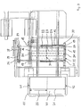
- Fig. 1 is a housing 1 consisting of side walls 2; 3 and trusses 4; 5; 6; 7; 8 indicated, in which a device for the round formation 9 of plate-shaped Cut and a welding system 10 is integrated.
- a plant table 11 is arranged on the plate-shaped blanks preferably in a trough and / or by means of stops and / or pre-centered markings can be stored manually.
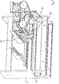
- system table 11 is a device for fixing the plate-shaped blank as a flat blank 40 in the form of a on the corresponding plate size adjustable plate suction frame 12 from the Housing 1 for receiving the raw form 40 by means of the feed table 11 a linear drive 13 mobile (Fig. 2).
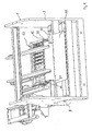
- the plate suction frame 12 comprises two steel strips 14; 15, one, here the Steel bar 15, corresponding to the distance between the plate edges 41; 42 of the blank 40 on one by means of a linear drive 16 driven carriage 17 adjustable and lengthways on the respective plate edge is positionable (Fig. 3).
- the position of the plate edge 42 at which the steel strip 15 is positioned is not shown in detail, by means of a sensor system arranged on the carriage 17 determined.
- the steel bar 14 is stationary via holding elements 18; 19 in the plate suction frame 12 arranged.
- the steel bar 15 is by means of holding elements 20; 21 on the slide 17 of the Plate intake frame 12 arranged.
- the holding elements 18 to 21 are preferably electrical Holding magnets executed with corresponding soft iron cores of the steel strips 14; 15 can work together.
- the plate suction frame 12 further comprises one with suction elements 22; 23 in plate 24 interspersed with a suitable grid.
- the suction elements 22 are stationary arranged. By means of these stationary suction elements 22 can Lowering the plate suction frame 12 by means of a lifting device 31 plate-shaped blank 40 sucked with a minimum length of 25 and on Plate suction frame 12 are fixed aligned.
- suction elements 22 can also be switched on and off on the raw form 40 be designed.
- the data on the length of the plate-like blank 40 will not be closer shown, stored in a machine control. From one to the device Person serving, for example, this data on the length of the plate-shaped raw form 40 via a keyboard in the machine control can be entered. According to the machine control entered length of the rough form 40 for a register-correct and flat Transport necessary suction elements 22; 23 activated automatically.
- an optical or mechanical scanning device the size, that is, both the length and the Width of the plate-shaped blank 40 automatically checked and recognized.
- One with control related to this scanner or The control device then automatically switches on for fixing Plate suction frame 12 required suction elements 22; 23 according to the determined Data regarding the length and width of the rough form 40 as needed.
- the plate-shaped raw form 40 becomes on it Top side, or on the side of the plant table 11 opposite Plattenansaugrahmens 12 kept ready for transport and is just aligned on Plate suction frame 12 fixed.
- the plate suction frame 12 is by means of the linear drive 13, which is a cable, a Rack or a chain guide supported in rails can be in the Housing 1 mobile over the device for round shaping 9.
- the end positions of the Travel path of the plate suction frame 12 are in and outside the housing 1 preferably determined by means of stops.
- the device for round shaping 9 is described in DE 43 11 078 C1 How it works is analogous to this.
- the plate edges 41; 42 is a fixedly arranged magnetic bar 27 and one rotatable about an axis 28 and a magnetic strip 30 which can be moved transversely along a sliding guide 29 intended.
- the magnetic strips 27; 30 preferably as electrical Holding magnets designed (Fig. 2; Fig. 6; Fig. 7).
- the transversely movable magnetic strip 30 is in accordance with the respective length the plate-shaped blank 40 positioned.
- the data for positioning the Transversely movable magnetic strip 30 are, for example, from the top described scanning device and / or the machine control available posed.
- the plate suction frame 12 is over the correspondingly adjusted magnetic strips 27; 30 positioned, the plate suction frame 12 via a Plate suction frame 12 arranged lifting device 31 in the direction of Magnetic strips 27; 30 lowered until the steel strips 14; 15 on the Magnetic strips 27; 30 concerns.
- the steel strips 14; 15 of the plate suction frame 12 are electromagnetically attractable and the plate-shaped raw form 40 on the Magnetic strips 27; 30 clampable.
- the empty plate suction frame 12 is so far from the work area Device for round shaping 9 can be moved up to, not shown in detail Housing closure, for example, a housing opening in front of possible outside escaping steel closes protectively.
- the magnetic strip 30 is rotated and at the same time transversely in Moved towards the fixed magnetic bar 27.
- the magnetic strip 30 passes under the fixed one Magnetic strip 27 and stands after a full rotation of the fixed Magnetic strip 27 opposite, so that the plate edges also face each other stand.
- the system table can also be used as one Be designed lifting device on which a stack of several plate-shaped raw molds can be placed.
- the lifting device By means of the lifting device the stack of plate-shaped blanks of the raw forms on the Plate suction frame 12 promoted.
- the plate suction frame takes from this Stack, starting from the top raw form, piece by piece a raw form aligned and transported to the device for round shaping 9.
- the device for Generation of a sleeve-shaped printing form after processing a stack of plates of plate-shaped blanks of the raw forms on the feed table or the Lifting device can be switched off automatically.
- a next stack of pallets arranged on a pallet Cuts to and on the lifting device are automatically brought and processed piece by piece.
- An endless production of sleeve-shaped printing forms are created.
- FIG. 3 shows the device according to the invention in the start position, the Plate suction frame 12 is parked in the housing 1, the device for round shaping 9 is in the starting position.
- the steel strips 14; 15 are on the Magnetic strips 27; 30. So that the rough form 40 can be brought in between, the steel strips 14; 15 can be raised. This is done using the on Plate suction frame 12 arranged holding elements 18 to 21.
- the holding elements 20; 21 for lifting the movable steel bar 15 from the movable magnetic bar are, as described above, by means of one Linear drive 16 driven carriage 17 movable and to the steel bar 15 positionable.
- the holding elements 20; 21 move from a minimal Plate length position 34 in the direction of maximum plate length position 35 to one carried sensors, not shown, the location of the magnetic strip 30 and the steel bar 15 seated on the magnetic bar 30 recognizes and the Holding elements 20; 21 in position.
- the start position is designed here in such a way that the location of the magnetic strip 30 and the steel bar 15 sitting on the magnetic bar 30 in the maximum Plate length position 35 is located.
- the location of the magnetic bar 30 and that on the Magnetic strip 30 seated steel strip 15 can alternatively, not shown in detail, are also in the minimum plate length position 34.
- the step of removing the finished sleeve-shaped printing form from the Housing 1 or from the device for round shaping 9, the removal by means of a conveyor and rolling over the welds in the Conveyor is also analogous to that in DE 197 10 901 C1 described devices and their operation. In this way, a multiple sequence of those described analogously in DE 197 10 901 C1 Work steps are carried out automatically.
- the device described in the exemplary embodiment is for processing plate-shaped raw forms, which are made of both non-magnetic material and can also consist of magnetic material, suitable.
- a variant of the device, not shown, is that in a Processing of plate-like raw forms made of a magnetic material consist of the suction elements described in the embodiment to replace electrical holding magnets, which like the suction elements the size of the Raw form can be switched on and off.
Landscapes
- Engineering & Computer Science (AREA)
- Mechanical Engineering (AREA)
- Physics & Mathematics (AREA)
- Optics & Photonics (AREA)
- Manufacturing & Machinery (AREA)
- Plasma & Fusion (AREA)
- Making Paper Articles (AREA)
- Specific Conveyance Elements (AREA)
- Sheets, Magazines, And Separation Thereof (AREA)
Abstract
Description
- Fig. 1
- eine Seitenansicht einer erfindungsgemäßen Vorrichtung zur Erzeugung einer hülsenförmigen Druckform,
- Fig. 2
- eine Forderansicht der erfindungsgemäßen Vorrichtung,
- Fig. 3
- eine Draufsicht der erfindungsgemäßen Vorrichtung,
- Fig. 4
- eine Ansicht von vorne oben aus betrachtet der erfindungsgemäßen Vorrichtung, wobei die Transportvorrichtung über den Anlagetisch verfahren ist,
- Fig. 5
- eine Ansicht von hinten unten aus betrachtet der erfindungsgemäßen Vorrichtung, wobei die Transportvorrichtung über den Anlagetisch verfahren ist,
- Fig. 6
- eine Ansicht von vorne oben aus betrachtet der erfindungsgemäßen Vorrichtung, wobei die Transportvorrichtung über die Magnetleisten verfahren ist, und
- Fig. 7
- eine Ansicht von hinten unten aus betrachtet der erfindungsgemäßen Vorrichtung, wobei die Transportvorrichtung über die Magnetleisten verfahren ist.
- 1
- Gehäuse
- 2
- Seitenwand
- 3
- Seitenwand
- 4
- Traverse
- 5
- Traverse
- 6
- Traverse
- 7
- Traverse
- 8
- Traverse
- 9
- Einrichtung zur Rundformung
- 10
- Schweißanlage
- 11
- Anlagetisch
- 12
- Plattenansaugrahmen
- 13
- Linearantrieb
- 14
- Stahlleiste
- 15
- Stahlleiste
- 16
- Linearantrieb
- 17
- Schlitten
- 18
- Halteelement
- 19
- Halteelement
- 20
- Halteelement
- 21
- Halteelement
- 22
- Saugelement
- 23
- Saugelement
- 24
- Platte
- 25
- Mindestlänge der Rohform
- 26
- Maximale Länge der Rohform
- 27
- Magnetleiste
- 28
- Achse
- 29
- Gleitführung
- 30
- Magnetleiste
- 31
- Hubvorrichtung
- 32
- Rundtisch
- 33
- Schlitten
- 34
- Minimale Plattenlängen-Position
- 35
- Maximale Plattenlängen-Position
- 36
- Schwenkarm
- 37
- Schwenkarm
- 38
- Halteelement
- 39
- Halteelement
- 40
- Rohform
- 41
- Plattenkante
- 42
- Plattenkante
Claims (13)
- Vorrichtung zur Erzeugung einer hülsenförmigen Druckform aus einem plattenförmigen Zuschnitt,
eine Einrichtung zur Rundformung der Rohform und
eine Schweißanlage, die in einem Gehäuse angeordnet sind, mittels dieser die den Anfang und Ende der Druckform bildenden Plattenkanten durch einen Laserstrahl maßhaltig zuschneidbar und verschweißbar sind,
außerhalb des Gehäuses einen Anlagetisch für die plattenförmige Rohform, und
eine über den Anlagetisch aus dem Gehäuse heraus fahrbare Einrichtung zur Aufnahme des plattenförmigen Zuschnitts der Rohform und zum Transport der Rohform an die Einrichtung zur Rundformung im Gehäuse umfassend,
dadurch gekennzeichnet, daß
die fahrbare Einrichtung aus einem Plattenansaugrahmen (12) besteht,
der Plattenansaugrahmen (12) mit Saugelementen (22; 23) durchsetzt ist, der Plattenansaugrahmen (12) an die auf dem Anlagetisch (11) aufzubringende Rohform (40) mit den Saugelementen (22; 23) berührend positionierbar ist, wobei nach Berührung der Rohform (40) diese mittels der ansaugenden Saugelemente (22; 23) am Plattenansaugrahmen (12) eben ausgerichtet fixiert ist und lagestabil zur Einrichtung zur Rundformung (9) transportierbar und an der Einrichtung zur Rundformung (9) eben ausgerichtet ablegbar und registergerecht fixierbar ist. - Vorrichtung nach Anspruch 1,
dadurch gekennzeichnet, daß
die Rohform (40) eine variable Größe aufweist. - Vorrichtung nach Anspruch 1, 2 oder 3,
dadurch gekennzeichnet, daß
der Plattenansaugrahmen (12) eine Platte (24) aufweist, wobei diese in Form eines Rasters mit den Saugelementen (22; 23) durchsetzt ist. - Vorrichtung nach einem der Ansprüche 1, 2 oder 3,
dadurch gekennzeichnet, daß
die Saugelemente (22) in einem Bereich einer Mindestlänge (25) der auf dem Anlagetisch (11) aufzubringenden Rohform (40) angeordnet sind und die Saugelemente (23) in einem Bereich zwischen der Mindestlänge (25) und einer maximalen Länge (26) der auf dem Anlagetisch (11) aufzubringenden Rohform (40) angeordnet sind. - Vorrichtung nach einem der Ansprüche 1 bis 4,
dadurch gekennzeichnet, daß
die Saugelemente (22; 23) entsprechend einer tatsächlichen Länge und/oder Breite der Rohform (40) in ihrer Saugwirkung zu- und abschaltbar sind. - Vorrichtung nach einem der Ansprüche 1 bis 4,
dadurch gekennzeichnet, daß
die Rohform (40) der Mindestlänge (25) mit ortsfest angeordneten und gleichzeitig die Rohform (40) ansaugenden Saugelementen (22) fixierbar ist und die über die Mindestlänge (25) hinausragende Rohform (40) mittels entsprechend ihrer tatsächlichen Länge zum ebenen fixieren benötigte an die Rohform (40) positionierbar und zuschaltbar ansaugende Saugelemente (23) fixierbar ist. - Vorrichtung nach einem der Ansprüche 1 bis 6,
dadurch gekennzeichnet, daß
der Plattenansaugrahmen (12) mittels einer Hubvorrichtung (31) an die auf dem Anlagetisch (11) aufzubringende Rohform (40) positionierbar ist. - Vorrichtung nach einem der Ansprüche 1 bis 7,
dadurch gekennzeichnet, daß
die Einrichtung zur Rundformung (9) für die zu verbindenden Plattenkanten (41; 42) eine feststehend angeordnete Magnetleiste (27) und eine auf einem drehbar und transversal bewegbar angeordneten Rundtisch (32) sitzende Magnetleiste (30) aufweist, wobei die feststehend angeordnete Magnetleiste (27) die erste Plattenkante (41) aufnimmt und die transversal bewegbare Magnetleiste (30) entsprechend der tatsächlichen Länge der Rohform (40) sich ergebenden Position der zweiten Plattenkante (42) zur Aufnahme dieser positionierbar ist. - Vorrichtung nach Anspruch 8,
dadurch gekennzeichnet, daß
bei einer vollen Umdrehung und gleichzeitig transversaler Verschiebung des Rundtisches (32) in Richtung der feststehenden Magnetleiste (27) die Magnetleisten (27; 30) unter Ausbildung einer Hülse zum maßhaltigen Ablängen und Verschweißen der Plattenkanten (41 ;42) in Position bringbar sind. - Vorrichtung nach einem der Ansprüche 1 bis 9,
dadurch gekennzeichnet, daß
die tatsächliche Länge und Breite der Rohform (40) mittels einer optischen oder mechanischen Abtastvorrichtung ermittelbar ist. - Vorrichtung nach Anspruch 10,
dadurch gekennzeichnet, daß
die Abtastvorrichtung die tatsächliche Länge und Breite der Rohform (40) in einer Maschinensteuerung übermittelbare Daten umwandelt, wobei gemäß der Daten die zum ebenen fixieren benötigten Saugelemente (22; 23) der Rohform (40) in ihrer Saugwirkung zu- und abschaltbar sind. - Vorrichtung nach einem der Ansprüche 1 bis 11,
dadurch gekennzeichnet, daß
auf den Anlagetisch (11) mehrere Rohformen in Form eines Plattenstapels legbar sind,
vom Plattenstapel die jeweils oben liegende Rohform (40) mittels des Plattenansaugrahmens (12) aufnehmbar ist und nach Abarbeitung des Plattenstapels selbsttätig abschaltbar ist. - Vorrichtung nach einem der Ansprüche 1 bis 12,
dadurch gekennzeichnet, daß
die Schweißanlage (3) in Form mindestens eines Lasers im Gehäuse (1) über der Einrichtung zur Rundformung (9) positioniert ist, so daß Laserschneiden und Laserschweißen maschinell durchführbar sind.
Applications Claiming Priority (2)
| Application Number | Priority Date | Filing Date | Title |
|---|---|---|---|
| DE10116609 | 2001-04-03 | ||
| DE10116609A DE10116609A1 (de) | 2001-04-03 | 2001-04-03 | Vorrichtung zur Erzeugung einer hülsenförmigen Druckform |
Publications (2)
| Publication Number | Publication Date |
|---|---|
| EP1247618A1 true EP1247618A1 (de) | 2002-10-09 |
| EP1247618B1 EP1247618B1 (de) | 2004-05-12 |
Family
ID=7680234
Family Applications (1)
| Application Number | Title | Priority Date | Filing Date |
|---|---|---|---|
| EP02006244A Expired - Lifetime EP1247618B1 (de) | 2001-04-03 | 2002-03-20 | Vorrichtung zur Erzeugung einer hülsenförmigen Druckform |
Country Status (3)
| Country | Link |
|---|---|
| US (1) | US6715418B2 (de) |
| EP (1) | EP1247618B1 (de) |
| DE (2) | DE10116609A1 (de) |
Families Citing this family (1)
| Publication number | Priority date | Publication date | Assignee | Title |
|---|---|---|---|---|
| DE10260445A1 (de) * | 2002-12-21 | 2004-07-08 | Man Roland Druckmaschinen Ag | Vorrichtung zur Erzeugung einer hülsenförmigen Druckform |
Citations (6)
| Publication number | Priority date | Publication date | Assignee | Title |
|---|---|---|---|---|
| DE4311078C1 (de) | 1993-04-03 | 1994-05-26 | Roland Man Druckmasch | Vorrichtung zur Erzeugung einer Hülse, insbesondere einer hülsenförmigen Druckform, mit zusammenhängender Umfangsfläche |
| DE4338467C1 (de) | 1993-11-11 | 1995-02-23 | Roland Man Druckmasch | Verfahren zur Herstellung einer hülsenförmigen Druckform |
| DE19710901C1 (de) | 1997-03-15 | 1998-08-13 | Roland Man Druckmasch | Vorrichtung zur Erzeugung einer hülsenförmigen Druckform |
| US5964568A (en) * | 1994-11-09 | 1999-10-12 | Codatto; Antonio | Device for gripping and handling pieces of sheet material and manipulator of pieces of sheet material comprising this device |
| EP0992317A2 (de) * | 1998-10-09 | 2000-04-12 | Murata Kikai Kabushiki Kaisha | Werkstückübergabevorrichtung |
| US6182957B1 (en) * | 1999-08-12 | 2001-02-06 | International Business Machines Corporation | Apparatus and method for holding a flexible product in a flat and secure position |
Family Cites Families (4)
| Publication number | Priority date | Publication date | Assignee | Title |
|---|---|---|---|---|
| GB1415835A (en) * | 1971-09-24 | 1975-11-26 | Mannesmann Meer Ag | Hydraulic presses |
| FR2633265B1 (fr) * | 1988-06-24 | 1991-06-07 | Centre Tech Cuir Chaussure | Dispositif pour la prehension de pieces souples isolees ou adjacentes, leur manipulation et leur depose, notamment de pieces en cuir et similaires |
| US6112663A (en) * | 1999-03-25 | 2000-09-05 | Creo Products Inc. | Method for loading a printing plate onto an imaging cylinder using a suction/pressure table |
| JP4343386B2 (ja) * | 2000-03-17 | 2009-10-14 | 富士フイルム株式会社 | 印刷版自動露光装置 |
-
2001
- 2001-04-03 DE DE10116609A patent/DE10116609A1/de not_active Withdrawn
-
2002
- 2002-03-20 DE DE50200420T patent/DE50200420D1/de not_active Expired - Lifetime
- 2002-03-20 EP EP02006244A patent/EP1247618B1/de not_active Expired - Lifetime
- 2002-04-02 US US10/114,147 patent/US6715418B2/en not_active Expired - Fee Related
Patent Citations (6)
| Publication number | Priority date | Publication date | Assignee | Title |
|---|---|---|---|---|
| DE4311078C1 (de) | 1993-04-03 | 1994-05-26 | Roland Man Druckmasch | Vorrichtung zur Erzeugung einer Hülse, insbesondere einer hülsenförmigen Druckform, mit zusammenhängender Umfangsfläche |
| DE4338467C1 (de) | 1993-11-11 | 1995-02-23 | Roland Man Druckmasch | Verfahren zur Herstellung einer hülsenförmigen Druckform |
| US5964568A (en) * | 1994-11-09 | 1999-10-12 | Codatto; Antonio | Device for gripping and handling pieces of sheet material and manipulator of pieces of sheet material comprising this device |
| DE19710901C1 (de) | 1997-03-15 | 1998-08-13 | Roland Man Druckmasch | Vorrichtung zur Erzeugung einer hülsenförmigen Druckform |
| EP0992317A2 (de) * | 1998-10-09 | 2000-04-12 | Murata Kikai Kabushiki Kaisha | Werkstückübergabevorrichtung |
| US6182957B1 (en) * | 1999-08-12 | 2001-02-06 | International Business Machines Corporation | Apparatus and method for holding a flexible product in a flat and secure position |
Also Published As
| Publication number | Publication date |
|---|---|
| US6715418B2 (en) | 2004-04-06 |
| DE50200420D1 (de) | 2004-06-17 |
| DE10116609A1 (de) | 2002-11-07 |
| EP1247618B1 (de) | 2004-05-12 |
| US20020139267A1 (en) | 2002-10-03 |
Similar Documents
| Publication | Publication Date | Title |
|---|---|---|
| DE2325519C3 (de) | Anlage zum Schneiden von Walzblech zu kombinierten Formaten | |
| DE69304112T2 (de) | Gerät und Verfahren zur Herstellung zweier oder mehrerer verschiedenen Arten geschweisster Paneele | |
| DE3804443C2 (de) | ||
| DE19621658C2 (de) | Bearbeitungsmaschine für plattenförmige Werkstücke, insbesondere zur Erzeugung von gebogenen Rändern an Blechteilen | |
| DE3744315C2 (de) | ||
| DE3915555C2 (de) | Blechbiegemaschine | |
| DE4232497C2 (de) | Vorrichtung zur Positionierung einer Karosserie auf einem Förderer | |
| DE10038757B4 (de) | Verfahren zur Herstellung von Betonfertigteilen | |
| EP1018408A1 (de) | Planschneidmaschine zum Schneiden von gestapeltem, blattförmigem Gut | |
| DE3101765C2 (de) | Werkzeugmaschine mit Werkstückzuführorganen | |
| EP1247618B1 (de) | Vorrichtung zur Erzeugung einer hülsenförmigen Druckform | |
| DE19710901C1 (de) | Vorrichtung zur Erzeugung einer hülsenförmigen Druckform | |
| EP0497780B1 (de) | Verfahren zum gegenläufigen biegen eines bleches | |
| EP1431033B1 (de) | Vorrichtung zur Erzeugung einer hülsenförmigen Druckform | |
| EP0498071A1 (de) | Verfahren zum Vorstapeln in einem Bogenanleger von Rotationsdruckmaschinen | |
| DE3431974C2 (de) | ||
| EP0478903A1 (de) | Wechselkassettenvorrichtung für eine Rollenrotationsdruckmaschine | |
| EP0300137A2 (de) | Abkantgerät | |
| EP3790678B1 (de) | Verfahren mit einer fertigungseinrichtung zum umformen von blech | |
| DE4316338C2 (de) | Halte- und Transportvorrichtung für insbesondere flächige Werkstücke | |
| AT526521B1 (de) | Fertigungsanlage mit einem Manipulator | |
| DE10313299B4 (de) | Magazin für Blechzuschnitte | |
| EP0764728B1 (de) | Vorrichtung zur Bearbeitung der an der Oberseite einer Blockanode vorhandenen Zapfenlöcher | |
| DE10050012C2 (de) | Verfahren und Vorrichtung zum Schneiden von Blechen | |
| DE2222582A1 (de) | Transporteinrichtung fuer platinen an automatischen nutenstanzmaschinen |
Legal Events
| Date | Code | Title | Description |
|---|---|---|---|
| PUAI | Public reference made under article 153(3) epc to a published international application that has entered the european phase |
Free format text: ORIGINAL CODE: 0009012 |
|
| AK | Designated contracting states |
Kind code of ref document: A1 Designated state(s): AT BE CH CY DE DK ES FI FR GB GR IE IT LI LU MC NL PT SE TR |
|
| AX | Request for extension of the european patent |
Free format text: AL;LT;LV;MK;RO;SI |
|
| 17P | Request for examination filed |
Effective date: 20021010 |
|
| 17Q | First examination report despatched |
Effective date: 20030117 |
|
| AKX | Designation fees paid |
Designated state(s): CH DE FR GB LI |
|
| GRAP | Despatch of communication of intention to grant a patent |
Free format text: ORIGINAL CODE: EPIDOSNIGR1 |
|
| GRAS | Grant fee paid |
Free format text: ORIGINAL CODE: EPIDOSNIGR3 |
|
| GRAA | (expected) grant |
Free format text: ORIGINAL CODE: 0009210 |
|
| AK | Designated contracting states |
Kind code of ref document: B1 Designated state(s): CH DE FR GB LI |
|
| REG | Reference to a national code |
Ref country code: GB Ref legal event code: FG4D Free format text: NOT ENGLISH |
|
| REG | Reference to a national code |
Ref country code: CH Ref legal event code: EP |
|
| REG | Reference to a national code |
Ref country code: IE Ref legal event code: FG4D Free format text: GERMAN |
|
| REF | Corresponds to: |
Ref document number: 50200420 Country of ref document: DE Date of ref document: 20040617 Kind code of ref document: P |
|
| GBT | Gb: translation of ep patent filed (gb section 77(6)(a)/1977) |
Effective date: 20040824 |
|
| ET | Fr: translation filed | ||
| REG | Reference to a national code |
Ref country code: IE Ref legal event code: FD4D |
|
| PLBE | No opposition filed within time limit |
Free format text: ORIGINAL CODE: 0009261 |
|
| STAA | Information on the status of an ep patent application or granted ep patent |
Free format text: STATUS: NO OPPOSITION FILED WITHIN TIME LIMIT |
|
| 26N | No opposition filed |
Effective date: 20050215 |
|
| REG | Reference to a national code |
Ref country code: CH Ref legal event code: PFA Owner name: MAN ROLAND DRUCKMASCHINEN AG Free format text: MAN ROLAND DRUCKMASCHINEN AG#POSTFACH 10 12 64#63012 OFFENBACH (DE) -TRANSFER TO- MAN ROLAND DRUCKMASCHINEN AG#POSTFACH 10 12 64#63012 OFFENBACH (DE) |
|
| REG | Reference to a national code |
Ref country code: CH Ref legal event code: PFA Owner name: MANROLAND AG Free format text: MAN ROLAND DRUCKMASCHINEN AG#POSTFACH 10 12 64#63012 OFFENBACH (DE) -TRANSFER TO- MANROLAND AG#MUEHLHEIMER STRA?E 341#63075 OFFENBACH (DE) |
|
| REG | Reference to a national code |
Ref country code: FR Ref legal event code: CD |
|
| PGFP | Annual fee paid to national office [announced via postgrant information from national office to epo] |
Ref country code: FR Payment date: 20110404 Year of fee payment: 10 Ref country code: CH Payment date: 20110324 Year of fee payment: 10 |
|
| PGFP | Annual fee paid to national office [announced via postgrant information from national office to epo] |
Ref country code: GB Payment date: 20110321 Year of fee payment: 10 Ref country code: DE Payment date: 20110325 Year of fee payment: 10 |
|
| REG | Reference to a national code |
Ref country code: CH Ref legal event code: PL |
|
| GBPC | Gb: european patent ceased through non-payment of renewal fee |
Effective date: 20120320 |
|
| REG | Reference to a national code |
Ref country code: FR Ref legal event code: ST Effective date: 20121130 |
|
| PG25 | Lapsed in a contracting state [announced via postgrant information from national office to epo] |
Ref country code: FR Free format text: LAPSE BECAUSE OF NON-PAYMENT OF DUE FEES Effective date: 20120402 Ref country code: LI Free format text: LAPSE BECAUSE OF NON-PAYMENT OF DUE FEES Effective date: 20120331 Ref country code: GB Free format text: LAPSE BECAUSE OF NON-PAYMENT OF DUE FEES Effective date: 20120320 Ref country code: CH Free format text: LAPSE BECAUSE OF NON-PAYMENT OF DUE FEES Effective date: 20120331 |
|
| REG | Reference to a national code |
Ref country code: DE Ref legal event code: R119 Ref document number: 50200420 Country of ref document: DE Effective date: 20121002 |
|
| PG25 | Lapsed in a contracting state [announced via postgrant information from national office to epo] |
Ref country code: DE Free format text: LAPSE BECAUSE OF NON-PAYMENT OF DUE FEES Effective date: 20121002 |