EP1247600A2 - Verfahren zur Herstellung von Kolben- bzw. Kolbenbauteilen sowie Schmiedewerkzeug - Google Patents
Verfahren zur Herstellung von Kolben- bzw. Kolbenbauteilen sowie Schmiedewerkzeug Download PDFInfo
- Publication number
- EP1247600A2 EP1247600A2 EP01109280A EP01109280A EP1247600A2 EP 1247600 A2 EP1247600 A2 EP 1247600A2 EP 01109280 A EP01109280 A EP 01109280A EP 01109280 A EP01109280 A EP 01109280A EP 1247600 A2 EP1247600 A2 EP 1247600A2
- Authority
- EP
- European Patent Office
- Prior art keywords
- piston
- forging
- tool
- parts
- base body
- Prior art date
- Legal status (The legal status is an assumption and is not a legal conclusion. Google has not performed a legal analysis and makes no representation as to the accuracy of the status listed.)
- Withdrawn
Links
Images


Classifications
-
- B—PERFORMING OPERATIONS; TRANSPORTING
- B21—MECHANICAL METAL-WORKING WITHOUT ESSENTIALLY REMOVING MATERIAL; PUNCHING METAL
- B21J—FORGING; HAMMERING; PRESSING METAL; RIVETING; FORGE FURNACES
- B21J5/00—Methods for forging, hammering, or pressing; Special equipment or accessories therefor
- B21J5/06—Methods for forging, hammering, or pressing; Special equipment or accessories therefor for performing particular operations
- B21J5/12—Forming profiles on internal or external surfaces
-
- B—PERFORMING OPERATIONS; TRANSPORTING
- B21—MECHANICAL METAL-WORKING WITHOUT ESSENTIALLY REMOVING MATERIAL; PUNCHING METAL
- B21J—FORGING; HAMMERING; PRESSING METAL; RIVETING; FORGE FURNACES
- B21J13/00—Details of machines for forging, pressing, or hammering
- B21J13/02—Dies or mountings therefor
- B21J13/025—Dies with parts moving along auxiliary lateral directions
-
- B—PERFORMING OPERATIONS; TRANSPORTING
- B21—MECHANICAL METAL-WORKING WITHOUT ESSENTIALLY REMOVING MATERIAL; PUNCHING METAL
- B21J—FORGING; HAMMERING; PRESSING METAL; RIVETING; FORGE FURNACES
- B21J5/00—Methods for forging, hammering, or pressing; Special equipment or accessories therefor
- B21J5/02—Die forging; Trimming by making use of special dies ; Punching during forging
-
- B—PERFORMING OPERATIONS; TRANSPORTING
- B21—MECHANICAL METAL-WORKING WITHOUT ESSENTIALLY REMOVING MATERIAL; PUNCHING METAL
- B21J—FORGING; HAMMERING; PRESSING METAL; RIVETING; FORGE FURNACES
- B21J9/00—Forging presses
- B21J9/02—Special design or construction
- B21J9/027—Special design or construction with punches moving along auxiliary lateral directions
-
- B—PERFORMING OPERATIONS; TRANSPORTING
- B21—MECHANICAL METAL-WORKING WITHOUT ESSENTIALLY REMOVING MATERIAL; PUNCHING METAL
- B21K—MAKING FORGED OR PRESSED METAL PRODUCTS, e.g. HORSE-SHOES, RIVETS, BOLTS OR WHEELS
- B21K1/00—Making machine elements
- B21K1/18—Making machine elements pistons or plungers
-
- F—MECHANICAL ENGINEERING; LIGHTING; HEATING; WEAPONS; BLASTING
- F02—COMBUSTION ENGINES; HOT-GAS OR COMBUSTION-PRODUCT ENGINE PLANTS
- F02B—INTERNAL-COMBUSTION PISTON ENGINES; COMBUSTION ENGINES IN GENERAL
- F02B3/00—Engines characterised by air compression and subsequent fuel addition
- F02B3/06—Engines characterised by air compression and subsequent fuel addition with compression ignition
-
- F—MECHANICAL ENGINEERING; LIGHTING; HEATING; WEAPONS; BLASTING
- F02—COMBUSTION ENGINES; HOT-GAS OR COMBUSTION-PRODUCT ENGINE PLANTS
- F02F—CYLINDERS, PISTONS OR CASINGS, FOR COMBUSTION ENGINES; ARRANGEMENTS OF SEALINGS IN COMBUSTION ENGINES
- F02F7/00—Casings, e.g. crankcases
- F02F2007/0097—Casings, e.g. crankcases for large diesel engines
-
- Y—GENERAL TAGGING OF NEW TECHNOLOGICAL DEVELOPMENTS; GENERAL TAGGING OF CROSS-SECTIONAL TECHNOLOGIES SPANNING OVER SEVERAL SECTIONS OF THE IPC; TECHNICAL SUBJECTS COVERED BY FORMER USPC CROSS-REFERENCE ART COLLECTIONS [XRACs] AND DIGESTS
- Y10—TECHNICAL SUBJECTS COVERED BY FORMER USPC
- Y10S—TECHNICAL SUBJECTS COVERED BY FORMER USPC CROSS-REFERENCE ART COLLECTIONS [XRACs] AND DIGESTS
- Y10S29/00—Metal working
- Y10S29/018—Method or apparatus with forging
-
- Y—GENERAL TAGGING OF NEW TECHNOLOGICAL DEVELOPMENTS; GENERAL TAGGING OF CROSS-SECTIONAL TECHNOLOGIES SPANNING OVER SEVERAL SECTIONS OF THE IPC; TECHNICAL SUBJECTS COVERED BY FORMER USPC CROSS-REFERENCE ART COLLECTIONS [XRACs] AND DIGESTS
- Y10—TECHNICAL SUBJECTS COVERED BY FORMER USPC
- Y10T—TECHNICAL SUBJECTS COVERED BY FORMER US CLASSIFICATION
- Y10T29/00—Metal working
- Y10T29/49—Method of mechanical manufacture
- Y10T29/49229—Prime mover or fluid pump making
- Y10T29/49249—Piston making
-
- Y—GENERAL TAGGING OF NEW TECHNOLOGICAL DEVELOPMENTS; GENERAL TAGGING OF CROSS-SECTIONAL TECHNOLOGIES SPANNING OVER SEVERAL SECTIONS OF THE IPC; TECHNICAL SUBJECTS COVERED BY FORMER USPC CROSS-REFERENCE ART COLLECTIONS [XRACs] AND DIGESTS
- Y10—TECHNICAL SUBJECTS COVERED BY FORMER USPC
- Y10T—TECHNICAL SUBJECTS COVERED BY FORMER US CLASSIFICATION
- Y10T29/00—Metal working
- Y10T29/49—Method of mechanical manufacture
- Y10T29/49995—Shaping one-piece blank by removing material
Definitions
- the invention relates to a method for producing pistons or Piston components, such as piston heads, in particular for Internal combustion engines.
- DE-A 3801847 is a method for producing pistons for To remove internal combustion engines, with each piston at least one has metallic reinforcing part. That from a material with open Pore existing metallic reinforcement part is heated and in one preheated die introduced. A predeterminable amount is placed in the die an aluminum or aluminum alloy melt introduced. In the A die is inserted so that the aluminum or Aluminum alloy is pressurized during its solidification, whereby the metal under pressure flows around the metallic reinforcement part, the Piston shape fills and thereby the open pores of the metallic Filling reinforcement part. After the melt solidifies, the piston becomes with the metallic reinforcement part removed from the die and the The pistons are then machined to their final dimensions.
- DE-A 19935410 is a piston, in particular for one Internal combustion engine, has become known of a bolt hole having piston skirt and an adjoining ring field having. Starting from the bolt hole, webs extend in the direction of the ring field and / or in the direction of the end facing away from the ring field Piston skirt. Such a piston is preferably made by casting generated.
- DE-A 3222582 describes a method for producing a piston crown for a built piston, especially for large diesel engines, described with vaulted piston crown middle part encircling piston crown shoulder and inner rotating hub, with the piston crown shoulder intended for receiving piston rings and for placing on one separately manufactured piston skirt is set up, on which the circumferential Hub can be connected by means of screwing and / or welding.
- Out a forgeable heat-resistant steel is in a first Deforming a cup forged the one of the piston crown middle part corresponding area and a circumferential collar. After that in a second deformation step with further shaping of the Piston crown middle part from the collar, the piston crown shoulder, as well as the Forged all-round hub. That kind of forging in Axial direction of the piston crown only allows contours with predeterminable Wall thicknesses, especially radial wall thicknesses, with an increased Material costs are given with a correspondingly weight-intensive design.
- the invention has for its object a method for producing To design pistons or piston components, such as piston heads, by means of which the easily wearing aluminum aprons are dispensable and with reduced material expenditure, an optimized wall thickness lightweight piston or a corresponding piston component, such as a Piston head, is available.
- a forging tool is also designed by means of which such pistons or piston components in a simple manner can be produced, and also complicated designs are possible should.
- This object is achieved by a method for producing pistons or piston components, such as piston heads, in particular for Internal combustion engines by the in a first step later pistons or the later piston component resulting body in a definable axis direction by shaping corresponding contours pre-forged and in at least one further step the preformed piston body in at least one other axial direction Forming further contours is forged.
- This object is also achieved by using a forging tool several in the area of upper and lower die parts
- Tool parts that are used to pre-shape and shape pistons or piston components, like piston heads, in several planes formed by axes in the direction of a base body are movable, with tool parts at least one of the Die parts for pre-forging and tool parts for at least one of the Die parts can be used for finish forging.
- the piston is biaxial Forging a basic body made of steel, the forging axes are preferably perpendicular to each other. at more complex piston geometries, it is also conceivable that the Forging is carried out in at least one other level, which is then inclined to the above-mentioned perpendicular planes lies.
- the piston or piston component solves this The problem with conventional configurations, namely premature wear of aluminum aprons, characterized in that the piston or the piston component a (made of steel) has integrated guide apron. That in DE-A 3222582 The method described does not provide any suggestions for this.
- an optionally rod-like base body can also filigree contours are created that were previously only possible using casting technology were and with the least possible use of materials.
- Fig. 1 shows a schematic diagram of the manufacturing process for the production of Piston heads.
- a rod-shaped base body 1 made of steel is heated (for example induction heating) and in one if necessary preheated die compressed in the axial direction 1 '.
- the base body 1 is in the same die and in the same axial direction a hollow body 2 and formed first radial peripheral surfaces 3 are given in a corresponding manner.
- 4 first profiles 5 are in the area of the upper end face formed.
- Side regions 6 are formed on by further shaping and optimizes the contour of the cavity 2, the side areas 6 the Correspond to the outer radius of the hollow body 2.
- the preformed piston body 7 is freed from excess material 8.
- the previously described Forming of the base body 1 up to the production of the preformed Piston body 7 correspond to a first step A, especially since all circumferences Formations in the same axial direction (arrow) have been made.
- a second tool can now be found in one and the same forging tool Forming process of the preformed piston body 7 instead of by the each other opposite sides 6 are subjected to a radial compression, so that they are within the limits of the diameter of the preformed Piston body 7 are positioned. Possibly. material parts 9 that are not required removed, this process depends on the component and does not necessarily has taken place.
- Fig. 2 shows a schematic diagram of a forging tool 10 consisting of a upper die part 11 and a lower die part 12.
- the left side of Fig. 2 shows the forging tool 10 in the open state, while the right side of Fig. 2, the forging tool 10 in the closed state represents.
- Tool parts 13, 14, 15 are provided in the upper die part 11, while the lower die part 12 contains tool parts 16, 17.
- the in lower die part 12 positioned tool parts 16 are over Hydraulic cylinder 18 can be actuated in the direction of the arrow.
- the tool parts 13, 16 are in operative connection with sliding surfaces 19, 20 in the lower die part 12.
- For the first step A is the upper die part 11 together with tool parts 13, 14, 15 moved in the axial direction 1 'of the lower die part 12.
- the Tool parts 16 have assumed a corresponding basic position, thus the transformations in FIG. 1 for work step A in perpendicular direction can be performed.
- the tool parts 16 via the hydraulic cylinder 18 in radial Axis direction 1 "delivered so that the basis of step B. lying transformations can be brought about.
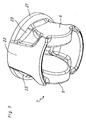
- Fig. 3 shows a spatial representation of the basic body 1 in the course multi-axis forging steps A, B Piston head 7, the side areas 6 within the limits of Diameter 21 are provided.
- the side areas 6 will be later bored out and serve for the sleeve-free reception of a compared to the State of the art, short piston pin, not shown.
- the piston skirt 22, which corresponds to the diameter 21 of the piston head 7 corresponds, is intended in a wall thickness-optimized form and runs under Formation of webs 23 in the radially recessed side regions 6.
Landscapes
- Engineering & Computer Science (AREA)
- Mechanical Engineering (AREA)
- Forging (AREA)
- Pistons, Piston Rings, And Cylinders (AREA)
Abstract
Description
- Fig. 1
- Prinzipskizze des Herstellvorganges von Kolbenköpfen
- Fig. 2
- Prinzipskizze eines erfindungsgemäßen Schmiedewerkzeuges
- Fig. 3
- Nach dem Verfahren gem. Fig. 1 in einem Schmiedewerkzeug gem. Fig. 2 geschmiedeter Kolbenkopf
- 1
- Grundkörper
- 1'
- Achsrichtung
- 1"
- Achsrichtung
- 2
- Hohlkörper
- 3
- radiale Umfangsfläche
- 4
- obere Stirnfläche
- 5
- Profilierungen
- 6
- Seitenbereich
- 7
- vorgeformter Kolbenkörper (Kolbenkopf)
- 8
- Materialüberstand
- 9
- Materialteil
- 10
- Schmiedewerkzeug
- 11
- oberes Gesenkteil
- 12
- unteres Gesenkteil
- 13
- Werkzeugteil
- 14
- Werkzeugteil
- 15
- Werkzeugteil
- 16
- Werkzeugteil
- 17
- Werkzeugteil
- 18
- Hydraulikzylinder
- 19
- Gleitfläche
- 20
- Gleitfläche
- 21
- Durchmesser
- 22
- Kolbenschürze
- 23
- Steg
Claims (15)
- Verfahren zur Herstellung von Kolben bzw. Kolbenbauteilen wie Kolbenköpfen (7), insbesondere für Verbrennungskraftmaschinen, indem in einem ersten Arbeitsschritt (A) der den späteren Kolben bzw. das spätere Kolbenbauteil ergebende Grundkörper (1) in einer vorgebbaren Achsrichtung (1') durch Ausformung entsprechender Konturen (2,3,4,5,6) vorgeschmiedet und in mindestens einem weiteren Arbeitsschritt (B) der vorgeformte Kolbenkörper (7) in mindestens einer weiteren Achsrichtung (1'') unter Bildung weiterer Konturen (6) fertiggeschmiedet wird.
- Verfahren nach Anspruch 1, dadurch gekennzeichnet, daß der erste Arbeitsschritt (A) die Vorformung des Grundkörpers (1) in Richtung seiner Längsachse (1') umfaßt.
- Verfahren nach Anspruch 1 oder 2, dadurch gekennzeichnet, daß im ersten Arbeitsschritt (A) ein stabartiger, ggf. zylindrischer Grundkörper (1) gestaucht und unter Bildung einer Kolbenschürze (22) mit einem Hohlraum (2) versehen wird, wobei in dieser Achsrichtung (1')Konturen (3-6) im Bereich der inneren und äußeren Umfangs- (3) sowie oberen und unteren Stirnfläche (4) der Kolbenschürze (22) angeformt werden.
- Verfahren nach einem der Ansprüche 1 bis 3, dadurch gekennzeichnet, daß in dem weiteren Arbeitsschritt (B) am vorgeformten Kolbenkörper (7) in einer zweiten Achsrichtung (1") weitere Konturen (6) durch Schmieden etwa um 90° quer zur ersten Achsrichtung (1'), insbesondere der Längsachse, angeformt werden.
- Verfahren nach einem der Ansprüche 1 bis 4, dadurch gekennzeichnet, daß die Arbeitsschritte des Längs- (A) und des Querschmiedens (B) in dem gleichen Schmiedewerkzeug (10) durchgeführt werden, wobei der Grundkörper (1) vor Einbringung in das Schmiedewerkzeug (10) ggf. erwärmt wird.
- Verfahren nach einem der Ansprüche 1 bis 5, dadurch gekennzeichnet, daß im Verlauf des weiteren Arbeitsschrittes (B) die Wandstärken des vorgeformten Kolbenkörpers (7), ggf. unter Bildung von versteifenden Elementen (23), reduziert werden.
- Verfahren nach einem der Ansprüche 1 bis 6, dadurch gekennzeichnet, daß im Verlauf eines der Arbeitsschritte (A,B) am vorgeformten Kolbenkörper (7) eine integrierte Kolbenschürze (22) dergestalt angeformt wird, daß sie im Verlauf des Arbeitsschrittes (B) innerhalb der Grenzen des Durchmessers (21) der Kolbenschürze (22) vorgesehen wird.
- Verfahren nach einem der Ansprüche 1 bis 7, dadurch gekennzeichnet, daß ein Grundkörper (1) aus Stahl eingesetzt wird.
- Verfahren nach einem der Ansprüche 1 bis 8, dadurch gekennzeichnet, daß ggf. in einem weiteren Arbeitsschritt eine Umformung des Kolbenkörpers (7) in einer weiteren Ebene erfolgt.
- Verfahren nach einem der Ansprüche 1 bis 9, dadurch gekennzeichnet, daß bei der Herstellung insbesondere von Kolbenköpfen (7) im Verlauf mindestens eines der Arbeitsschritte (A,B) Materialüberstände (8) entfernt und/oder Ausnehmungen (9), insbesondere durch Stanzen, erzeugt werden.
- Schmiedewerkzeug, beinhaltend mehrere im Bereich oberer (11) und unterer Gesenkteile (12) vorgesehener Werkzeugteile (13,14,15,16,17) die zur Vor- und Ausformung von Kolben bzw. Kolbenbauteilen wie Kolbenköpfen (7) in mehreren, durch Achsen (1',1") gebildeten Ebenen in Richtung eines Grundkörpers (1) bewegbar sind, wobei Werkzeugteile (13-17) mindestens eines der Gesenkteile (11,12) für das Vorschmieden und Werkzeugteile (16) mindestens eines der Gesenkteile (12) für das Fertigschmieden einsetzbar sind.
- Schmiedewerkzeug nach Anspruch 11, dadurch gekennzeichnet, daß diejenigen Werkzeugteile (13-15) des oberen Gesenkteiles (11) für das Vorschmieden und diejenigen Werkzeugteile (16,17) des unteren Gesenkteiles (12) für das Fertigschmieden einsetzbar sind.
- Schmiedewerkzeug nach einem der Ansprüche 11 oder 12, dadurch gekennzeichnet, daß die Werkzeugteile (16,17) des unteren Gesenkteiles (12) etwa 90° quer zur Bewegungsrichtung der Werkzeugteile (13-15) des oberen Gesenkteiles (11) bewegbar sind.
- Schmiedewerkzeug nach einem der Ansprüche 11 bis 13, dadurch gekennzeichnet, daß die Werkzeugteile (16) des unteren Gesenkteiles (12) insbesondere durch Hydraulikzylinder (18) quer zu den Werkzeugteilen (13-15) des oberen Gesenkteiles (11) bewegbar sind.
- Schmiedewerkzeug nach einem der Ansprüche 11 bis 14, dadurch gekennzeichnet, daß die einzelnen Werkzeugteile (13,16) des oberen (11) sowie des unteren Gesenkteiles (12) im Bereich des unteren Gesenkteiles (12) mit in unterschiedlichen Ebenen angeordneten Gleitflächen (19,20) in Eingriff bringbar sind.
Applications Claiming Priority (2)
| Application Number | Priority Date | Filing Date | Title |
|---|---|---|---|
| DE10113629 | 2001-03-21 | ||
| DE10113629A DE10113629A1 (de) | 2001-03-21 | 2001-03-21 | Verfahren zur Herstellung von Kolben- bzw. Kolbenbauteilen sowie Schmiedewerkzeug |
Publications (2)
| Publication Number | Publication Date |
|---|---|
| EP1247600A2 true EP1247600A2 (de) | 2002-10-09 |
| EP1247600A3 EP1247600A3 (de) | 2003-05-02 |
Family
ID=7678303
Family Applications (1)
| Application Number | Title | Priority Date | Filing Date |
|---|---|---|---|
| EP01109280A Withdrawn EP1247600A3 (de) | 2001-03-21 | 2001-04-17 | Verfahren zur Herstellung von Kolben- bzw. Kolbenbauteilen sowie Schmiedewerkzeug |
Country Status (3)
| Country | Link |
|---|---|
| US (1) | US7213337B1 (de) |
| EP (1) | EP1247600A3 (de) |
| DE (1) | DE10113629A1 (de) |
Cited By (1)
| Publication number | Priority date | Publication date | Assignee | Title |
|---|---|---|---|---|
| WO2011015351A1 (en) * | 2009-08-05 | 2011-02-10 | Mahle International Gmbh | Piston assembly multiple step forming process |
Families Citing this family (9)
| Publication number | Priority date | Publication date | Assignee | Title |
|---|---|---|---|---|
| FR2854089B1 (fr) * | 2003-04-23 | 2006-05-19 | Semt Pielstick | Procede de fabrication d'un piston, outillage pour la mise en oeuvre de ce procede et piston ainsi obtenu |
| DE102005041000B4 (de) * | 2005-08-29 | 2012-07-05 | Thyssenkrupp Automotive Ag | Verfahren, Fertigungslinie und Kolbenrohling zum Herstellen eines einteilig ausgebildeten Kolbens für Verbrennungsmotoren, sowie Kolben für Verbrennungsmotoren |
| DE102006020861B4 (de) * | 2006-05-04 | 2010-08-26 | Gesenkschmiede Schneider Gmbh | Einstufiges Schmiedeverfahren und Vorrichtung zur Herstellung von buchsenartigen Schmiedeteilen |
| DE102009040120A1 (de) * | 2009-09-04 | 2011-03-10 | Mahle International Gmbh | Verfahren zur Herstellung eines Aluminiumkolbens für einen Verbrennungsmotor |
| DE102011078145A1 (de) * | 2011-06-27 | 2012-12-27 | Mahle International Gmbh | Schmiedeverfahren zur Herstellung eines Kolbens bzw. Kolbenschafts |
| DE102011115048A1 (de) | 2011-10-07 | 2013-04-11 | Mahle International Gmbh | Schmiedevorrichtung zur Herstellung eines Kolbenrohlings und Verfahren zur Herstellung des Kolbenrohlings unter Verwendung der Schmiedevorrichtung |
| CN102397968B (zh) * | 2011-11-15 | 2016-10-05 | 洛阳秦汉精工股份有限公司 | 一种异种金属复合活塞锻装工艺 |
| DE102018207874B4 (de) * | 2018-05-18 | 2023-10-26 | Federal-Mogul Nürnberg GmbH | Verfahren zum multidirektionalen Schmieden eines Kolbens |
| CN115194081B (zh) * | 2022-06-07 | 2025-03-21 | 中国机械总院集团北京机电研究所有限公司 | 一种活塞四工位锻造工艺 |
Family Cites Families (21)
| Publication number | Priority date | Publication date | Assignee | Title |
|---|---|---|---|---|
| US2539903A (en) * | 1946-12-05 | 1951-01-30 | Smith Corp A O | Piston fabrication |
| US3010186A (en) * | 1954-01-14 | 1961-11-28 | Thompson Ramo Wooldridge Inc | Piston manufacture |
| US3152523A (en) * | 1962-08-16 | 1964-10-13 | Whitfield Lab Inc | Piston for internal combustion engines |
| DE2307347A1 (de) * | 1973-02-15 | 1974-08-22 | Maschf Augsburg Nuernberg Ag | Mehrteiliger tauchkolben fuer viertaktbrennkraftmaschinen, insbesondere grossdieselmotoren |
| US4083292A (en) * | 1976-06-16 | 1978-04-11 | Caterpillar Tractor Co. | Piston with high top ring location |
| DE3222582C2 (de) * | 1982-06-16 | 1985-10-03 | Berchem & Schaberg Gmbh, 4650 Gelsenkirchen | Verfahren zum Herstellen eines Kolbenbodenrohlings durch Schmieden für einen gebauten Kolben |
| DE3343623A1 (de) * | 1983-12-02 | 1985-06-13 | Thyssen Industrie AG Schmiedetechnik/Bergbautechnik, 4100 Duisburg | Schmiedepresse und steuerung dafuer |
| DE3502248C1 (de) * | 1985-01-24 | 1986-05-07 | Berchem & Schaberg Gmbh, 4650 Gelsenkirchen | Verfahren zur Herstellung eines einteiligen Kolbens fuer einen Verbrennungsmotor durch Schmieden |
| JPS63119944A (ja) * | 1986-11-10 | 1988-05-24 | Honda Motor Co Ltd | ピストンの鍛造方法 |
| JPH0620570B2 (ja) * | 1986-11-19 | 1994-03-23 | 本田技研工業株式会社 | ピストンの鍛造方法 |
| DE3713241A1 (de) * | 1986-12-24 | 1988-07-07 | Mahle Gmbh | Als rohling gegossener kopf eines zweiteiligen kolbens |
| BR8700527A (pt) * | 1987-01-29 | 1988-08-16 | Metal Leve Sa | Processo de fabricacao de embolo e embolo para motores de combustao interna |
| JP2543372B2 (ja) * | 1987-09-04 | 1996-10-16 | 曙ブレーキ工業株式会社 | ダボ付きピストンの製造方法 |
| DE3811200A1 (de) * | 1988-04-01 | 1989-10-19 | Berchem & Schaberg Gmbh | Kolbenrohling fuer einen geschmiedeten kolben |
| BR9001859A (pt) * | 1990-04-17 | 1991-11-12 | Metal Leve Sa | Processo de fabricacao de embolo e embolo |
| DE4014705C2 (de) * | 1990-05-08 | 1999-06-10 | Mahle Gmbh | Gekühlter Tauchkolben für Verbrennungsmotoren mit voneinander getrenntem Kolbenoberteil und Kolbenschaft |
| EP0864660B1 (de) * | 1997-02-12 | 2003-05-14 | Yamaha Hatsudoki Kabushiki Kaisha | Kolben für eine Brennkraftmaschine und Verfahren seiner Herstellung |
| JP3705676B2 (ja) * | 1997-04-10 | 2005-10-12 | ヤマハ発動機株式会社 | 内燃機関用ピストンの製造方法 |
| US6112642A (en) * | 1998-10-06 | 2000-09-05 | Caterpillar Inc. | Method and apparatus for making a two piece unitary piston |
| US6266878B1 (en) * | 1999-02-02 | 2001-07-31 | Amcast Industrial Corporation | Process for producing variable displacement compressor pistons having hollow piston bodies and integral actuator rods |
| DE19935410A1 (de) * | 1999-07-30 | 2001-02-08 | Ks Kolbenschmidt Gmbh | Kolben, insbesondere für eine Brennkraftmaschine |
-
2001
- 2001-03-21 DE DE10113629A patent/DE10113629A1/de not_active Withdrawn
- 2001-04-17 EP EP01109280A patent/EP1247600A3/de not_active Withdrawn
- 2001-04-19 US US09/837,951 patent/US7213337B1/en not_active Expired - Fee Related
Cited By (1)
| Publication number | Priority date | Publication date | Assignee | Title |
|---|---|---|---|---|
| WO2011015351A1 (en) * | 2009-08-05 | 2011-02-10 | Mahle International Gmbh | Piston assembly multiple step forming process |
Also Published As
| Publication number | Publication date |
|---|---|
| US7213337B1 (en) | 2007-05-08 |
| EP1247600A3 (de) | 2003-05-02 |
| DE10113629A1 (de) | 2002-10-02 |
Similar Documents
| Publication | Publication Date | Title |
|---|---|---|
| DE60122533T2 (de) | Kolben und verfahren zur herstellung | |
| DE60204296T2 (de) | Verfahren zur herstellung von einstückigen kolben | |
| DE4112576C2 (de) | Verfahren zur Herstellung eines Kolbens und nach diesem Verfahren hergestellter Kolben | |
| DE102005041000B4 (de) | Verfahren, Fertigungslinie und Kolbenrohling zum Herstellen eines einteilig ausgebildeten Kolbens für Verbrennungsmotoren, sowie Kolben für Verbrennungsmotoren | |
| DE3009656A1 (de) | Verfahren zur herstellung einer nockenwelle durch schmieden | |
| EP1198678B1 (de) | Kolben für einen hydraulischen druckraum | |
| EP1646460B1 (de) | Ringförmige verbundwerkstücke und ein kaltwalzverfahren zu ihrer fertigung | |
| EP1680256A1 (de) | Verfahren zur herstellung eines kolbens für einen verbrennungsmotor | |
| EP1247600A2 (de) | Verfahren zur Herstellung von Kolben- bzw. Kolbenbauteilen sowie Schmiedewerkzeug | |
| DE3106457C2 (de) | Verfahren zum Herstellen einer Nockenwelle oder dergleichen, und Vorrichtung zur Durchführung eines solchen Verfahrens | |
| EP1815124B1 (de) | Verfahren zur herstellung eines kolbens fuer einen verbrennungsmotor | |
| DE10150999A1 (de) | Verfahren zum Profilieren der äußeren Umfangsfläche von Zylinderlaufbuchsen | |
| EP1502011B1 (de) | Einstückig ausgebildeter nocken und verfahren zum herstellen des nockens sowie zusammenbau einer steuerwelle oder nockenwelle | |
| DE19617831A1 (de) | Verfahren zur Herstellung von Zahnrädern | |
| DE102007003679B4 (de) | Verfahren zur Herstellung eines Kolbens für eine Brennkraftmaschine mit einem Kühlkanal, realisiert durch Fügen des Kolbenoberteiles und des Kolbenunterteiles mit Hilfe einer Schmiede-Stauchverbindung | |
| DE102005021428A1 (de) | Verfahren zur Herstellung eines geschmiedeten Kolbens | |
| EP1378628B1 (de) | Hohlkolben für eine Kolbenmaschine und Verfahren zum Herstellen eines Hohlkolbens | |
| EP0826450B1 (de) | Verfahren zur Kalibrierung einer vorgeformten Ausnehmung | |
| EP0963264B1 (de) | Verfahren zur herstellung eines gehäuseblocks für ein hydraulikaggregat und der gehäuseblock | |
| DE3425048A1 (de) | Verfahren zur herstellung eines rotors fuer eine rotationsfluidpumpe | |
| DE19703530C1 (de) | Zylinderlaufbuchse mit einer Verengung der Zylinderbohrung und Verfahren zur Herstellung einer Zylinderlaufbuchse | |
| EP2976181B1 (de) | Verfahren zur herstellung eines kolbens für einen verbrennungsmotor | |
| DE10152316B4 (de) | Verfahren zur Herstellung eines Kolbens | |
| DE69313302T2 (de) | Verfahren zur herstellung von pleuelstangen | |
| DE19939873A1 (de) | Kolben für einen hydraulischen Druckraum |
Legal Events
| Date | Code | Title | Description |
|---|---|---|---|
| PUAI | Public reference made under article 153(3) epc to a published international application that has entered the european phase |
Free format text: ORIGINAL CODE: 0009012 |
|
| AK | Designated contracting states |
Kind code of ref document: A2 Designated state(s): AT BE CH CY DE DK ES FI FR GB GR IE IT LI LU MC NL PT SE TR |
|
| AX | Request for extension of the european patent |
Free format text: AL;LT;LV;MK;RO;SI |
|
| PUAL | Search report despatched |
Free format text: ORIGINAL CODE: 0009013 |
|
| AK | Designated contracting states |
Designated state(s): AT BE CH CY DE DK ES FI FR GB GR IE IT LI LU MC NL PT SE TR |
|
| AX | Request for extension of the european patent |
Extension state: AL LT LV MK RO SI |
|
| STAA | Information on the status of an ep patent application or granted ep patent |
Free format text: STATUS: THE APPLICATION HAS BEEN WITHDRAWN |
|
| 18W | Application withdrawn |
Effective date: 20030528 |