EP1245296A1 - Coating installation with sprayhead changing station - Google Patents
Coating installation with sprayhead changing station Download PDFInfo
- Publication number
- EP1245296A1 EP1245296A1 EP02007053A EP02007053A EP1245296A1 EP 1245296 A1 EP1245296 A1 EP 1245296A1 EP 02007053 A EP02007053 A EP 02007053A EP 02007053 A EP02007053 A EP 02007053A EP 1245296 A1 EP1245296 A1 EP 1245296A1
- Authority
- EP
- European Patent Office
- Prior art keywords
- coating
- station
- changing station
- storage spaces
- atomizer
- Prior art date
- Legal status (The legal status is an assumption and is not a legal conclusion. Google has not performed a legal analysis and makes no representation as to the accuracy of the status listed.)
- Granted
Links
Images


Classifications
-
- B—PERFORMING OPERATIONS; TRANSPORTING
- B25—HAND TOOLS; PORTABLE POWER-DRIVEN TOOLS; MANIPULATORS
- B25J—MANIPULATORS; CHAMBERS PROVIDED WITH MANIPULATION DEVICES
- B25J15/00—Gripping heads and other end effectors
- B25J15/04—Gripping heads and other end effectors with provision for the remote detachment or exchange of the head or parts thereof
- B25J15/0491—Gripping heads and other end effectors with provision for the remote detachment or exchange of the head or parts thereof comprising end-effector racks
-
- B—PERFORMING OPERATIONS; TRANSPORTING
- B05—SPRAYING OR ATOMISING IN GENERAL; APPLYING FLUENT MATERIALS TO SURFACES, IN GENERAL
- B05B—SPRAYING APPARATUS; ATOMISING APPARATUS; NOZZLES
- B05B12/00—Arrangements for controlling delivery; Arrangements for controlling the spray area
- B05B12/14—Arrangements for controlling delivery; Arrangements for controlling the spray area for supplying a selected one of a plurality of liquids or other fluent materials or several in selected proportions to a spray apparatus, e.g. to a single spray outlet
- B05B12/1454—Arrangements for controlling delivery; Arrangements for controlling the spray area for supplying a selected one of a plurality of liquids or other fluent materials or several in selected proportions to a spray apparatus, e.g. to a single spray outlet separate units comprising both a material container and a spray device permanently connected thereto being removably attached to a part of the spray apparatus, e.g. to a robot arm
-
- B—PERFORMING OPERATIONS; TRANSPORTING
- B05—SPRAYING OR ATOMISING IN GENERAL; APPLYING FLUENT MATERIALS TO SURFACES, IN GENERAL
- B05B—SPRAYING APPARATUS; ATOMISING APPARATUS; NOZZLES
- B05B13/00—Machines or plants for applying liquids or other fluent materials to surfaces of objects or other work by spraying, not covered by groups B05B1/00 - B05B11/00
- B05B13/02—Means for supporting work; Arrangement or mounting of spray heads; Adaptation or arrangement of means for feeding work
- B05B13/04—Means for supporting work; Arrangement or mounting of spray heads; Adaptation or arrangement of means for feeding work the spray heads being moved during spraying operation
- B05B13/0431—Means for supporting work; Arrangement or mounting of spray heads; Adaptation or arrangement of means for feeding work the spray heads being moved during spraying operation with spray heads moved by robots or articulated arms, e.g. for applying liquid or other fluent material to 3D-surfaces
-
- Y—GENERAL TAGGING OF NEW TECHNOLOGICAL DEVELOPMENTS; GENERAL TAGGING OF CROSS-SECTIONAL TECHNOLOGIES SPANNING OVER SEVERAL SECTIONS OF THE IPC; TECHNICAL SUBJECTS COVERED BY FORMER USPC CROSS-REFERENCE ART COLLECTIONS [XRACs] AND DIGESTS
- Y10—TECHNICAL SUBJECTS COVERED BY FORMER USPC
- Y10T—TECHNICAL SUBJECTS COVERED BY FORMER US CLASSIFICATION
- Y10T483/00—Tool changing
- Y10T483/10—Process
-
- Y—GENERAL TAGGING OF NEW TECHNOLOGICAL DEVELOPMENTS; GENERAL TAGGING OF CROSS-SECTIONAL TECHNOLOGIES SPANNING OVER SEVERAL SECTIONS OF THE IPC; TECHNICAL SUBJECTS COVERED BY FORMER USPC CROSS-REFERENCE ART COLLECTIONS [XRACs] AND DIGESTS
- Y10—TECHNICAL SUBJECTS COVERED BY FORMER USPC
- Y10T—TECHNICAL SUBJECTS COVERED BY FORMER US CLASSIFICATION
- Y10T483/00—Tool changing
- Y10T483/17—Tool changing including machine tool or component
Definitions
- the invention relates to a coating system and a method according to the preamble of the independent claims.
- a coating system and a method according to the preamble of the independent claims.
- a system for coating of workpieces such as vehicle bodies with one or more painting robots with exchangeable atomizers in a spray booth.
- the interchangeable atomizers can be expediently coated with material storage containers filled with different colors contain.
- the object of the invention is with a space-saving as possible Exchange system a quick replacement of the atomizer another atomizer or against a tool if necessary such as a measuring device or gripping tool etc. to enable.
- the atomizer in the changing station easier than before on supply lines for coating material and to common pipe systems for cleaning media, Compressed air, etc. can be connected.
- the atomizer data required include information like operating hours; Listing of the painting zone, Paint line, paint type, etc. in which the atomizer is used has been; List of paint quantity (liter output or standby mode); maintenance work carried out; carried out cleaning work. From the atomizer data, for example Maintenance instructions are obtained.
- the automatically movable one for example serving as a rondelle Bracket can advantageously also be moved within the cabin be, in particular linear parallel to the conveying direction of the coating workpieces and thus to the corresponding one 7th axis of the robot, so that the required atomizer, for example can drive towards the robot to save time.
- a particularly important option is the storage spaces containing device, so possibly the Rondell to be arranged on the cabin wall or preferably as part of this wall, that they quickly move from the inside of the cabin on the one hand and on the other hand is accessible from the outside. From the inside the atomizers or tools can be picked up by a robot and used while from the outside, for example, manual Switching is possible.
- The, for example, circular storage device can be special advantageously be arranged so that the common center of the storage spaces, that is to say the circular axis if necessary, in the plane of the Cabin wall lies, the cabin wall level through the middle the storage device runs.
- the outer part of the device in an extension e.g. to be arranged with a door that can only be used if necessary Change of atomizer or other tools open becomes.
- the one accessible to the robot in the cabin interior Part can be closed with an access panel be provided for the robot that is opened when necessary.
- the storage device can also by e.g. airflow serving as an air curtain protected become.
- the storage device rotatable shell construction in the cabin wall can be installed, for example a cylinder half-shell.
- the interior of this only open on one side Shell construction is from the outside depending on its rotational position or accessible from the inside of the cabin, in both Cases the cabin is closed to the outside.
- the exchange station described here is also advantageously simple expandable, and not just by increasing the Rondells, but especially by connecting additional magazines.
- FIG. 1A shows a coating system with an atomizer change station and a coating robot 151.
- the coating robot 151 can at a removal station 110 from a in the exchange station Rondell 112 ( Figure 2) with coating material filled atomizer 7 for coating Remove workpieces.
- the exchange station 150 is with one for cover 153 which can be opened and closed by the robot, through which the Rondell 110 from unwanted pollution is protected.
- the robot is inside one with cabin walls 154 provided cabin on a linear guide 155 movable and can thus from the exchange station 150 to the Workpieces (not shown in detail) to be coated.
- the exchange station 150 shows the exchange station from a different viewing direction without cover and cabin walls.
- the robot 151 can turn off the atomizer 7 provided with the paint container 7 to coat a workpiece. After the robot an atomizer 7 with the empty paint containers in again the Rondell 110 has returned, the paint container and the atomizer is cleaned in a cleaning station 164 are then placed in a filling station, not shown here to be refilled with coating material.
- the exchange station 150 also has a manual input station 165 for the manual input and removal of atomizers on.
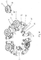
- FIG. 2A shows another view of a change station 100 with the rotatable atomizer circular 112.
- the atomizer circular 112 has six storage spaces 2, on which the atomizer 7 can be stored.
- the Storage spaces 2 are integrated in a holding plate 10. ever after how many atomizers 7 are received by the holding plate 10 their size can vary and thus the number of storage spaces 2. Depending on the desired embodiment can therefore have different sizes. Independently are of the size of the exchange station described here the storage spaces 2 and thus the atomizers 7 in a circle a common center 1 arranged, the holding plate 10 is rotatable about the center.
- the Rondell 112 and possibly the exchange station 100 can be linear within the cabin (Fig.
- the exchange station has a flushing and Filling station 9 with which the paint container 8 of the atomizer 7 can be rinsed and filled with new paint (See Fig. 2B arrow 9 ').
- the exchange station can be in the area the cabin wall (not shown here) (Fig. 1A) so arranged that both the robots inside the cabin as well operating personnel from outside the cabin to those in the Storage spaces 2 arranged atomizer 7 can access.
- Covers not shown, machine-controlled Doors or an air curtain can contaminate prevent the atomizer 7 stored in the roundel 1.
- the circular Arrangement of the atomizer 7 in the storage spaces 2 facilitated it, simultaneously with 2 robots on the one in the Rondell 1 stored atomizer 7 to access.
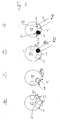
- the figures 3a to 3d show the sequence of changing the atomizers 7 by two robots 5 and one representing the rondelle rotatable rotary table 20.
- the robots 5 the rotary table 20 in the direction of the arrows 21 and 22 atomizer 7 ' with paint containers previously emptied during coating.
- In the rinsing and filling stations 9 are atomizers 7 with filled paint containers.
- the rotary table 20 is in the direction of the arrow 24 rotated further around a storage space so that the filled atomizer 7 to the transfer stations 23 to get there from Robot to be picked up in the direction of arrows 25 and 26.
- the empty atomizers 7 By rotating the rotary table 20 in the direction of arrow 24 the empty atomizers 7 'move one storage place further to the rinsing and filling stations 9.
- rotary table 20 in two storage spaces Turned back in the direction of arrows 28 so that the not with a Atomizers 7 occupy storage spaces 2 in the position the atomizing, depositing and removal stations (transfer stations 23 in Fig. 3a) in which they are emptied by the robot Can hold 5 delivered atomizers.
- Fig. 4a shows the process of changing atomizers with only a robot.
- a swivel unit 30 with two storage spaces 2 is at a stationary transfer station 23 and a stationary Rinsing and filling station 9 arranged.
- the robot 5 lays an empty atomizer 7 'coming from the direction of arrow 31 on the swivel unit 30 as shown in Fig. 4a.
- the swivel unit 30 is in the direction of the arrow 32 rotated and a previously filled (Fig. 4a) atomizer 7 picked up by robot 5 and in the direction of arrow 33 removed.
- the swivel unit 30 is in the direction of the arrow 32 opposite direction of arrows 34 by two storage spaces has been rotated so that the one deposited by the robot 5 in FIG empty atomizers 7 'rinsed in the rinsing and filling station 9 and can be filled.
- the swivel unit 30 by two storage spaces rotated in the direction of arrows 35 corresponding to arrow 32, so that by removing the full atomizer 7 in Fig. 4b free space 2 at the transfer station 23 for receiving an empty atomizer 7.
- FIG. 5 shows a swivel unit 30 according to FIG. 4, which is a rotatable Magazine 40 is assigned (for e.g. 4 to 10 storage spaces) ,
- the robot 5 brings the direction of the arrow in FIG. 5a 41 an empty atomizer 7 'coming to the transfer station 23.
- the swivel unit 30 by two storage spaces rotated in the opposite direction of arrows 45 and that in Fig. 5a deposited empty atomizers 7 'in the rinsing and filling station 9 rinsed and filled. Then the swivel unit 30 um three storage spaces rotated in the direction of arrows 46 (Fig. 5d) and the atomizer 7 filled in Fig. 5c into position of the empty magazine slot 42. Then the magazine 40 rotated in the direction of arrows 47 (Fig. 5e) and the Another filled atomizer 7 is fed to the swivel unit 30.
- the swivel unit 30 rotated until the empty one is not with a paint container occupied storage space 2 reaches the transfer position 23 (Fig. 5a) to the robot 5 again an empty atomizer to be able to record.
- Fig. 6 shows an embodiment of the holding plate 10 of the in 2 change station 100 shown.
- the holding plate 10th has six fork-shaped recesses forming the storage spaces 2 in which the atomizers in the direction of arrow 2 ' introduced their flange parts 7 "which can be detached from the robot can be.
- One preferably in all three spatial axes on Storage space 2 floating tool storage 56 has media connections 50 for air, detergent and other operating media, Interrogators 52 for tool identification and an adjustable spring-loaded pin 55.
- connection counterparts 51 e.g. Air connections, which are closed when uncoupled, with the media connections 50 connected, e.g. for air supply for one pneumatic locking.
- the connections 50 can also for Earth the atomizer used.
- the interrogators 52 of the storage spaces 2 are when the atomizer is inserted with interchangeably arranged inserts in the flange part 7 " 53 associated for type recognition.
- the interaction the bolt 55 with the centering device 54 is used Fixing the position of the flange part 7 '' in the normal direction of the holding plate 10.
- the 58 recognizable elements are is formed, for example, by ball thrust pieces Device for centering the storage fork in a prescribed Position in a prism insert.
- the exchange station described here can also advantageously be used as fully automatic changing device for the fully automatic Control and improvement of the coating quality during of the paint shop using suitable quality measuring sensors serve, the measurement results for immediate, preferably also automatic correction of the coating parameters can be used in the same painting station.
- This can (especially in painting systems with relatively long Cycle times) the same robot both for painting with possibly different application tools such as Air and rotary atomizers as well as for immediately following Result measurement and subsequent painting with if necessary corrected process parameters (color quantity, high voltage, Air, speed, etc.) can be used.
Abstract
Description
Die Erfindung betrifft eine Beschichtungsanlage und ein Verfahren nach dem Oberbegriff der unabhängigen Patentansprüche. Insbesondere handelt es sich um eine Anlage für die Beschichtung von Werkstücken wie Fahrzeugkarossen mit einem oder mehr Lackierrobotern mit auswechselbaren Zerstäubern in einer Sprühkabine.The invention relates to a coating system and a method according to the preamble of the independent claims. In particular is a system for coating of workpieces such as vehicle bodies with one or more painting robots with exchangeable atomizers in a spray booth.
Es ist bekannt, auswechselbar an Lackierrobotern montierbare Zerstäuber in einer Reihe im Innenraum der Lackierkabine anzuordnen, wo sie von den Robotern nach Bedarf abgeholt werden können. Dieser Vorgang erfordert relativ viel Zeit. Entsprechendes gilt für die erforderliche Versorgung und Reinigung der Zerstäuber in der Wechselstation. Im übrigen haben bisher bekannte Wechselanordnungen unerwünscht hohen Platzbedarf.It is known to be interchangeable on painting robots Arrange atomizers in a row in the interior of the paint booth where they are picked up by the robots as needed can. This process takes a relatively long time. The same applies to the necessary supply and cleaning of the Atomizer in the exchange station. For the rest, have known so far Change arrangements undesirably high space requirements.
Die auswechselbaren Zerstäuber können zweckmäßig mit Beschichtungsmaterial unterschiedlicher Farbe gefüllte Vorratsbehälter enthalten.The interchangeable atomizers can be expediently coated with material storage containers filled with different colors contain.
Aufgabe der Erfindung ist, mit einem möglichst platzsparenden Wechselsystem ein schnelles Auswechseln der Zerstäuber gegen einen anderen Zerstäuber oder bei Bedarf auch gegen ein Werkzeug wie beispielsweise ein Messgerät oder Greifwerkzeug usw. zu ermöglichen.The object of the invention is with a space-saving as possible Exchange system a quick replacement of the atomizer another atomizer or against a tool if necessary such as a measuring device or gripping tool etc. to enable.
Diese Aufgabe wird durch die Merkmale der Patentansprüche gelöst.This object is solved by the features of the claims.
Durch die hier beschriebene Rondellform wird eine sehr kompakte, platzsparende und insbesondere bei Drehbarkeit schnell und einfach zugreifbare Wechselstation geschaffen, die nicht nur für die zu wechselnden Zerstäuber, sondern auch für sonstige während des Beschichtungsbetriebes von einem Roboter benötigte Geräte oder Werkzeuge zur Verfügung steht. Bei der Drehbewegung kann es sich um eine vollständige (karussellartige) Rotation oder um einfaches Verschwenken handeln.Due to the circular shape described here, a very compact, space-saving and especially when it is rotatable quickly and easily accessible exchange station created that not only for the atomizer to be changed, but also for others needed by a robot during the coating operation Devices or tools are available. When turning can be a complete (carousel-like) rotation or just swivel.
Vorteilhaft ist ferner, dass die Zerstäuber in der Wechselstation einfacher als bisher an Versorgungsleitungen für Beschichtungsmaterial und an gemeinsame Leitungssysteme für Reinigungsmedien, Druckluft usw. angeschlossen werden können.It is also advantageous that the atomizer in the changing station easier than before on supply lines for coating material and to common pipe systems for cleaning media, Compressed air, etc. can be connected.
Ferner ermöglicht es ein in der Wechselstation vorgesehenes I-dentifikationssystem für die Zerstäuber in dem Rondell auf besonders einfache Weise, die für die Instandhaltung relevanten Zerstäuberdaten auszulesen und den Zerstäubertyp dem Ablageplatz zuzuordnen. Zu den benötigten Zerstäuberdaten gehören Informationen wie Betriebsstunden; Auflistung der Lackierzone, Lackierlinie, Lackart usw., in der der Zerstäuber eingesetzt wurde; Auflistung der Lackiermenge (Literleistung bzw. Standby-Betrieb); ausgeführte Wartungsarbeiten; ausgeführte Reinigungsarbeiten. Aus den Zerstäuberdaten können beispielsweise Wartungshinweise gewonnen werden.It also enables an identification system provided in the exchange station for the atomizers in the rondelle on especially simple way that is relevant for maintenance Read atomizer data and the atomizer type of the storage place assigned. The atomizer data required include information like operating hours; Listing of the painting zone, Paint line, paint type, etc. in which the atomizer is used has been; List of paint quantity (liter output or standby mode); maintenance work carried out; carried out cleaning work. From the atomizer data, for example Maintenance instructions are obtained.
Die automatisch bewegbare, beispielsweise als Rondell dienende Halterung kann vorteilhaft auch innerhalb der Kabine verfahrbar sein, insbesondere linear parallel zur Förderrichtung der zu beschichtenden Werkstücke und somit zu der ihr entsprechenden 7. Achse des Roboters, so dass der benötigte Zerstäuber beispielsweise dem Roboter zur Zeiteinsparung entgegenfahren kann.The automatically movable one, for example serving as a rondelle Bracket can advantageously also be moved within the cabin be, in particular linear parallel to the conveying direction of the coating workpieces and thus to the corresponding one 7th axis of the robot, so that the required atomizer, for example can drive towards the robot to save time.
Eine besonders wichtige Möglichkeit besteht darin, die die Ablageplätze enthaltende Vorrichtung, also ggf. das Rondell an der Kabinenwand oder vorzugsweise als Teil dieser Wand so anzuordnen, dass sie schnell einerseits vom Inneren der Kabine aus und andererseits von außen her zugänglich ist. Von innen her können die Zerstäuber oder Werkzeuge von einem Roboter abgeholt und eingesetzt werden, während von außerhalb beispielsweise manuelles Wechseln möglich ist.A particularly important option is the storage spaces containing device, so possibly the Rondell to be arranged on the cabin wall or preferably as part of this wall, that they quickly move from the inside of the cabin on the one hand and on the other hand is accessible from the outside. From the inside the atomizers or tools can be picked up by a robot and used while from the outside, for example, manual Switching is possible.
Die beispielsweise rondellartige Ablagevorrichtung kann besonders vorteilhaft so angeordnet sein, dass die gemeinsame Mitte der Ablageplätze, also ggf. die Rondellachse, in der Ebene der Kabinenwand liegt, die Kabinenwandebene also durch die Mitte der Ablagevorrichtung verläuft.The, for example, circular storage device can be special advantageously be arranged so that the common center of the storage spaces, that is to say the circular axis if necessary, in the plane of the Cabin wall lies, the cabin wall level through the middle the storage device runs.
Zur Abdeckung der Ablagevorrichtung besteht u.a. die Möglichkeit, den außen liegenden Teil der Vorrichtung in einem Anbau z.B. mit einer Tür anzuordnen, die nur bei Bedarf etwa zum Wechsel eines Zerstäubers oder sonstiger Werkzeuge geöffnet wird. Auch der für den Roboter im Kabineninnenraum zugängliche Teil kann mit einer geschlossenen Verkleidung mit einem Zugang für den Roboter versehen sein, der bei Bedarf geöffnet wird. Zusätzlich oder stattdessen kann die Ablagevorrichtung auch durch eine z.B. als Luftvorhang dienende Luftströmung geschützt werden.To cover the storage device, there is the possibility, the outer part of the device in an extension e.g. to be arranged with a door that can only be used if necessary Change of atomizer or other tools open becomes. Also the one accessible to the robot in the cabin interior Part can be closed with an access panel be provided for the robot that is opened when necessary. In addition or instead, the storage device can also by e.g. airflow serving as an air curtain protected become.
Insbesondere wenn sich das Drehzentrum der Ablagevorrichtung in oder in der Nähe der Ebene der Kabinenwand befindet, kann zweckmäßig als Abdeckung statt fester Anbauten eine um die Mittelachse der Ablagevorrichtung drehbare Schalenkonstruktion in die Kabinenwand eingebaut werden, beispielsweise eine Zylinderhalbschale. Der Innenraum dieser nur nach einer Seite offenen Schalenkonstruktion ist je nach ihrer Drehstellung von außen oder von der Kabineninnenseite her zugänglich, wobei in beiden Fällen die Kabine nach außen hin abgeschlossen ist.Especially when the center of rotation of the storage device in or located near the plane of the cabin wall useful as a cover instead of fixed attachments around the central axis the storage device rotatable shell construction in the cabin wall can be installed, for example a cylinder half-shell. The interior of this only open on one side Shell construction is from the outside depending on its rotational position or accessible from the inside of the cabin, in both Cases the cabin is closed to the outside.
Vorteilhaft ist die hier beschriebene Wechselstation auch einfach erweiterbar, und zwar nicht nur durch Vergrößerung des Rondells, sondern insbesondere durch Anschluss zusätzlicher Magazine. The exchange station described here is also advantageously simple expandable, and not just by increasing the Rondells, but especially by connecting additional magazines.
Anhand der Zeichnung werden verschiedene Ausführungsbeispiele einer erfindungsgemäßen Beschichtungsanlage näher erläutert. Es zeigen:
- Fign. 1A und 1B
- perspektivische Ansichten einer Zerstäuberwechselstation in einer Beschichtungsanlage;
- Fign. 2A und 2B
- perspektivische Ansichten eines drehbaren Zerstäuberrondells der Wechselstation;
- Fig. 3a bis d
- einen Zerstäuberwechsel für zwei Roboter mit einem Rondell;
- Fig. 4a bis d
- einen Zerstäuberwechsel für einen Roboter mit Rondell;
- Fig. 5a bis e
- einen Zerstäuberwechsel mit der Schwenkeinheit aus Fig. 3 und einem Magazin;
- Fig. 6
- eine Halteplatte des Rondells.
- FIGS. 1A and 1B
- perspective views of an atomizer change station in a coating system;
- FIGS. 2A and 2B
- perspective views of a rotatable atomizer roundel of the changing station;
- 3a to d
- an atomizer change for two robots with a rondelle;
- 4a to d
- an atomizer change for a robot with a rondelle;
- 5a to e
- an atomizer change with the swivel unit of Figure 3 and a magazine.
- Fig. 6
- a holding plate of the roundel.
Fig 1A zeigt eine Beschichtungsanlage mit einer Zerstäuberwechselstation
und einem Beschichtungsroboter 151. Der Beschichtungsroboter
151 kann an einer Entnahmestation 110 aus einem in
der Wechselstation befindlichen Rondell 112 (Figur 2) mit Beschichtungsmaterial
befüllte Zerstäuber 7 zur Beschichtung von
Werkstücken entnehmen. Die Wechselstation 150 ist mit einer für
den Roboter zu öffnenden und verschließbaren Abdeckung 153 versehen,
durch die das Rondell 110 vor unerwünschter Verschmutzung
geschützt wird. Der Roboter'ist innerhalb einer mit Kabinenwänden
154 versehenen Kabine auf einer Linearführung 155
verfahrbar und kann somit von der Wechselstation 150 zu den
(nicht näher gezeigten) zu beschichtenden Werkstücken gelangen. 1A shows a coating system with an atomizer change station
and a
Fig. 1B zeigt die Wechselstation aus einer anderen Blickrichtung
ohne Abdeckung und Kabinenwände. Der Roboter 151 kann aus
dem Rondell 110 die mit Farbbehältern versehenen Zerstäuber 7
zur Beschichtung eines Werkstücks entnehmen. Nachdem der Roboter
einen Zerstäuber 7 mit den leeren Farbbehältern wieder in
das Rondell 110 zurückgebracht hat, können der Farbbehälter
und der Zerstäuber in einer Reinigungsstation 164 gereinigt
werden, um sie anschließend in einer hier nicht gezeigten Befüllstation
wieder neu mit Beschichtungsmaterial zu befüllen.
Außerdem weist die Wechselstation 150 auch eine Handeingabestation
165 für die manuelle Eingabe und Entnahme von Zerstäubern
auf.1B shows the exchange station from a different viewing direction
without cover and cabin walls. The
Fig. 2A zeigt eine andere Ansicht einer Wechselstation 100 mit
dem drehbaren Zerstäuberrondell 112. In der dargestellten Ausführungsform
besitzt das Zerstäuberrondell 112 sechs Ablageplätze
2, an denen die Zerstäuber 7 gelagert werden können. Die
Ablageplätze 2 sind in einer Halteplatte 10 integriert. Je
nachdem wie viele Zerstäuber 7 von der Halteplatte 10 aufgenommen
werden sollen, kann ihre Größe variieren und somit die Anzahl
der Ablageplätze 2. Je nach gewünschter Ausführungsform
kann das Rondell also unterschiedliche Größen aufweisen. Unabhängig
von der Größe der hier beschriebenen Wechselstation sind
die Ablageplätze 2 und somit die Zerstäuber 7 kreisförmig um
eine ihnen gemeinsame Mitte 1 angeordnet, wobei die Halteplatte
10 um die Mitte drehbar ist. Das Rondell 112 und ggf. die Wechselstation
100 können linear innerhalb der Kabine (Fig. 1A)
verfahren werden, so dass die Zerstäuber 7 unter Zeiteinsparung
dem nicht näher dargestellten Roboter (Fign. 1A und 1B) zugeführt
werden können. Ferner weist die Wechselstation eine Spülund
Befüllstation 9 auf, mit der der Farbbehälter 8 des Zerstäubers
7 gespült und mit neuer Farbe befüllt werden kann
(siehe Fig. 2B Pfeil 9'). Die Wechselstation kann im Bereich
der hier nicht dargestellten Kabinenwand (Fig.1A) so angeordnet
werden, dass sowohl die Roboter innerhalb der Kabine als auch
das Bedienungspersonal von außerhalb der Kabine auf die in den
Ablageplätzen 2 angeordneten Zerstäuber 7 zugreifen können. Ebenfalls
nicht näher dargestellte Abdeckungen, maschinell gesteuerte
Türen oder ein Luftvorhang können das Verunreinigen
der im Rondell 1 gelagerten Zerstäuber 7 verhindern. Die kreisförmige
Anordnung der Zerstäuber 7 in den Ablageplätzen 2 erleichtert
es, gleichzeitig mit 2 Robotern auf die im Rondell 1
gelagerten Zerstäuber 7 zuzugreifen.2A shows another view of a change station 100 with
the
Die Fign. 3a bis 3d zeigen den Ablauf eines Wechsels der Zerstäuber
7 durch zwei Roboter 5 und einen das Rondell darstellenden
drehbaren Rundtisch 20. In Fig. 3a führen die Roboter 5
dem Rundtisch 20 in Richtung der Pfeile 21 und 22 Zerstäuber 7'
mit zuvor bei der Beschichtung entleerten Farbbehältern zu. Zur
Aufnahme der leeren Zerstäuber 7' stehen die an zwei stationären
Ablage- und Entnahme- oder Übergabestationen 23 befindlichen
Rondellplätze bereit. In den Spül- und Befüllstationen 9
befinden sich Zerstäuber 7 mit gefüllten Farbbehältern.The figures 3a to 3d show the sequence of changing the
Gemäß Fig. 3b wird der Rundtisch 20 in Richtung des Pfeiles 24
um einen Ablageplatz weiter gedreht, so dass die gefüllten Zerstäuber
7 zu den Übergabestationen 23 gelangen, um dort vom
Roboter in Richtung der Pfeile 25 und 26 aufgenommen zu werden.
Durch das Drehen des Rundtisches 20 in Richtung des Pfeiles 24
um einen Ablageplatz weiter gelangen die leeren Zerstäuber 7'
zu den Spül- und Befüllstationen 9.3b, the rotary table 20 is in the direction of the
In Fig. 3c wird der Rundtisch 20 in Richtung der Pfeile 27 um
zwei Ablageplätze weiter gedreht, so dass die zwei in Fig. 3b
dargestellten leeren Zerstäuber 7' zu den Spül- und Befüllstationen
9 weiter befördert worden sind, um dort gespült und befüllt
zu werden. Die durch die Aufnahme der beiden Zerstäuber 7
aus Fig. 3b frei gewordenen Ablageplätze befinden sich nun in
der in Fig. 3c ersichtlichen Position. In Fig. 3c the rotary table 20 is around in the direction of
Gemäß Fig. 3d wird der Rundtisch 20 um zwei Ablageplätze in
Richtung der Pfeile 28 zurückgedreht, so dass die nicht mit einem
Zerstäuber 7 besetzten Ablageplätze 2 in die Position an
den Zerstäuber-, Ablage- und Entnahmestationen (Übergabestationen
23 in Fig. 3a) gebracht werden, in der sie leere vom Roboter
5 angelieferte Zerstäuber aufnehmen können.According to Fig. 3d, the rotary table 20 in two storage spaces
Turned back in the direction of
Fig. 4a zeigt den Ablauf eines Wechsels von Zerstäubern mit nur
einem Roboter. Eine Schwenkeinheit 30 mit zwei Ablageplätze 2
ist an einer stationären Übergabestation 23 und einer stationären
Spül- und Befüllstation 9 angeordnet. Der Roboter 5 legt
aus Richtung des Pfeiles 31 kommend einen leeren Zerstäuber 7'
auf der Schwenkeinheit 30 ab, wie in Fig. 4a gezeigt ist.Fig. 4a shows the process of changing atomizers with only
a robot. A
Gemäß Fig. 4b wird die Schwenkeinheit 30 in Richtung des Pfeiles
32 gedreht und ein zuvor (Fig. 4a) befüllter Zerstäuber 7
vom Roboter 5 aufgenommen und in Richtung des Pfeiles 33
abtransportiert.4b, the
In Fig. 4c ist die Schwenkeinheit 30 in die zu dem Pfeil 32
entgegengesetzte Richtung der Pfeile 34 um zwei Ablageplätze
gedreht worden, so dass der in Fig. 4a vom Roboter 5 abgelegte
leere Zerstäuber 7' in der Spül- und Befüllstation 9 gespült
und befüllt werden kann.4c, the
Gemäß Fig. 4d wird die Schwenkeinheit 30 um zwei Ablageplätze
in der dem Pfeil 32 entsprechenden Richtung der Pfeile 35 gedreht,
so dass sich der durch Entnahme des vollen Zerstäubers 7
in Fig. 4b frei gewordene Ablageplatz 2 an der Übergabestation
23 zur Aufnahme eines entleerten Zerstäubers 7 befindet.According to Fig. 4d, the
Fig. 5 zeigt eine Schwenkeinheit 30 gemäß Fig. 4, der ein drehbares
Magazin 40 zugeordnet ist (für z.B. 4 bis 10 Ablageplätze)
. Der Roboter 5 bringt in Fig. 5a aus Richtung des Pfeiles
41 kommend einen leeren Zerstäuber 7' zur Übergabestation 23.
In der Spül- und Befüllstation 9 befindet sich ein befüllter
Zerstäuber 7. An der Verbindungsstelle zwischen der Schwenkeinheit
30 und dem Magazin 40 ist ein leerer Magazinplatz 42 vorhanden.FIG. 5 shows a
In Fig. 5b wurde die Schwenkeinheit 30 in Richtung des Pfeiles
43 gedreht, so dass der in Fig. 5a befüllte Zerstäuber 7 zur
Aufnahme durch den Roboter 5 bereit steht, um vom Roboter 5 in
Richtung des Pfeiles 44 abtransportiert zu werden.In Fig. 5b, the
Gemäß Fig. 5c wird die Schwenkeinheit 30 um zwei Ablageplätze
in die Gegenrichtung der Pfeile 45 gedreht und der in Fig. 5a
abgelegte leere Zerstäuber 7' in der Spül- und Befüllstation 9
gespült und befüllt. Anschließend wird die Schwenkeinheit 30 um
drei Ablageplätze in Richtung der Pfeile 46 (Fig. 5d) weitergedreht
und der in Fig. 5c befüllte Zerstäuber 7 auf die Position
des leeren Magazinplatzes 42 gebracht. Daraufhin wird das Magazin
40 in Richtung der Pfeile 47 gedreht (Fig. 5e) und der
Schwenkeinheit 30 ein anderer befüllter Zerstäuber 7 zugeführt.
Im nächsten hier nicht dargestellten Schritt wird die Schwenkeinheit
30 so weit gedreht, bis der leere nicht mit einem Farbbehälter
belegte Ablageplatz 2 auf die Übergabeposition 23 gelangt
(Fig. 5a), um vom Roboter 5 wieder einen leeren Zerstäuber
aufnehmen zu können.According to Fig. 5c, the
Fig. 6 zeigt eine Ausführungsform der Halteplatte 10 der in
Fig. 2 dargestellten Wechselstation 100. Die Halteplatte 10
weist sechs die Ablageplätze 2 bildende gabelförmige Ausnehmungen
auf, in die die Zerstäuber in Richtung des Pfeiles 2' mit
ihren vom Roboter abtrennbaren Flanschteilen 7" eingebracht
werden können. Eine vorzugsweise in allen drei Raumachsen am
Ablageplatz 2 schwimmend gelagerte Werkzeugablage 56 weist Medienanschlüsse
50 für Luft, Spülmittel und andere Betriebsmedien,
Abfrageeinrichtungen 52 zur Werkzeugidentifizierung und
einen einstellbaren federbelasteten Bolzen 55 auf. Beim Einsetzen
der Flanschteile 7" in die Ablage 2 werden an den Flanschteilen
angeordnete Anschlussgegenstücke 51, z.B. Luftanschlüsse,
die im abgekuppelten Zustand verschlossen sind, mit den Medienanschlüssen
50 verbunden, z.B. zur Luftversorgung für eine
pneumatische Verriegelung. Die Anschlüsse 50 können auch zum
Erden des eingesetzten Zerstäubers dienen. Die Abfrageeinrichtungen
52 der Ablageplätze 2 werden beim Einsetzen der Zerstäuber
mit im Flanschteil 7" auswechselbar angeordneten Einsätzen
53 für die Typenerkennung in Verbindung gebracht. Ferner weist
das Flanschteil 7" eine Zentriereinrichtung 54 auf, die beim
Einsetzen des Flanschteiles in den Ablageplatz 2 in einen einstellbaren
federbelasteten Bolzen 55 eingreift. Das Zusammenspiel
des Bolzens 55 mit der Zentriereinrichtung 54 dient der
Lagefixierung des Flanschteiles 7'' in Normalrichtung der Halteplatte
10. Bei den bei 58 erkennbaren Elementen handelt es
sich um eine beispielsweise durch Kugeldruckstücke gebildete
Einrichtung zur Zentrierung der Ablagegabel in einer vorgeschriebenen
Stellung in einem Prismeneinsatz.Fig. 6 shows an embodiment of the holding
Die hier beschriebene Wechselstation kann vorteilhaft auch als vollautomatische Wechseleinrichtung für die vollautomatische Kontrolle und Verbesserung der Beschichtungsqualität während des Lackierbetriebes unter Verwendung geeigneter Qualitätsmesssensoren dienen, deren Messergebnisse zur sofortigen, vorzugsweise ebenfalls automatischen Korrektur der Beschichtungsparameter in derselben Lackierstation verwendet werden können. Hierbei kann (insbesondere bei Lackieranlagen mit relativ langen Taktzeiten) derselbe Roboter sowohl zum Lackieren mit ggf. unterschiedlichen Applikationswerkzeugen wie beispielsweise Luft- und Rotationszerstäubern als auch zur unmittelbar anschließenden Ergebnismessung und anschließenden Lackierung mit ggf. korrigierten Prozessparametern (Farbmenge, Hochspannung, Luft, Drehzahl usw.) verwendet werden. The exchange station described here can also advantageously be used as fully automatic changing device for the fully automatic Control and improvement of the coating quality during of the paint shop using suitable quality measuring sensors serve, the measurement results for immediate, preferably also automatic correction of the coating parameters can be used in the same painting station. This can (especially in painting systems with relatively long Cycle times) the same robot both for painting with possibly different application tools such as Air and rotary atomizers as well as for immediately following Result measurement and subsequent painting with if necessary corrected process parameters (color quantity, high voltage, Air, speed, etc.) can be used.
Beispielsweise kann sich dann der folgende vollautomatische Betriebsablauf
im geschlossenen Regelkreis ergeben:
Claims (17)
dadurch gekennzeichnet, dass die Ablageplätze (2) um eine ihnen gemeinsame Mitte (1) einer bewegbaren Halterung (112) verteilt angeordnet sind.Coating system for the serial coating of workpieces with tools that can be detachably and interchangeably mounted on at least one coating machine (151), which are deposited and picked up by the coating machine (151) in a spray booth at storage locations (2) that can be approached by a tool change station (100),
characterized in that the storage spaces (2) are arranged distributed around a common center (1) of a movable holder (112).
dadurch gekennzeichnet, dass die Ablageplätze (2) innerhalb der Wechselstation (150) zu einer Übergabestation (23) für die Beschichtungsmaschine (151) bewegt und nach der Entnahme oder dem Einsetzen eines Werkzeugs (7) durch die Maschine (151) wieder von der Übergabestation (23) wegbewegt werden.Method for the serial coating of workpieces with detachably and interchangeably mounted tools on at least one coating machine (151), which are deposited and picked up by the coating machine in a spray booth at storage locations (2) of a tool changing station (15) which it approaches,
characterized in that the storage places (2) within the changing station (150) move to a transfer station (23) for the coating machine (151) and after the removal (or insertion) of a tool (7) by the machine (151) again from the transfer station (23) can be moved away.
dass die Messergebnisse mit gespeicherten Sollwerte verglichen und den Abweichungen entsprechende Korrekturwerte für die für die Abweichungen verantwortlichen Beschichtungsprozessparameter errechnet werden
und dass mit einem anschließend der Wechselstation (150) entnommenen Applikationswerkzeug (7) das zuvor beschichtete Werkstück nachbearbeitet und/oder nachfolgende Werkstücke unter Verwendung der korrigierten Beschichtungsprozessparameter beschichtet werden.Method according to claim 15, characterized in that the measuring device removed from the changing station (150) measures the color tone, gradient, layer thickness and / or another quality parameter of the previously produced coating,
that the measurement results are compared with stored target values and correction values corresponding to the deviations are calculated for the coating process parameters responsible for the deviations
and that with an application tool (7) subsequently removed from the changing station (150), the previously coated workpiece is reworked and / or subsequent workpieces are coated using the corrected coating process parameters.
Applications Claiming Priority (2)
| Application Number | Priority Date | Filing Date | Title |
|---|---|---|---|
| DE10115470A DE10115470A1 (en) | 2001-03-29 | 2001-03-29 | Coating system with an atomizer change station |
| DE10115470 | 2001-03-29 |
Publications (2)
| Publication Number | Publication Date |
|---|---|
| EP1245296A1 true EP1245296A1 (en) | 2002-10-02 |
| EP1245296B1 EP1245296B1 (en) | 2004-06-30 |
Family
ID=7679496
Family Applications (1)
| Application Number | Title | Priority Date | Filing Date |
|---|---|---|---|
| EP02007053A Expired - Lifetime EP1245296B1 (en) | 2001-03-29 | 2002-03-27 | Coating installation with sprayhead changing station |
Country Status (5)
| Country | Link |
|---|---|
| US (1) | US7018679B2 (en) |
| EP (1) | EP1245296B1 (en) |
| AT (1) | ATE270156T1 (en) |
| DE (2) | DE10115470A1 (en) |
| ES (1) | ES2221912T3 (en) |
Cited By (2)
| Publication number | Priority date | Publication date | Assignee | Title |
|---|---|---|---|---|
| WO2014075762A1 (en) * | 2012-11-16 | 2014-05-22 | Eisenmann Ag | Application robot having a connection unit for different applicators |
| DE102020128118A1 (en) | 2020-10-26 | 2022-04-28 | Dürr Systems Ag | Changing system for changing a mixer |
Families Citing this family (16)
| Publication number | Priority date | Publication date | Assignee | Title |
|---|---|---|---|---|
| DE10115463A1 (en) | 2001-03-29 | 2002-10-02 | Duerr Systems Gmbh | Atomizer for a coating system and process for its material supply |
| DE10115467A1 (en) | 2001-03-29 | 2002-10-02 | Duerr Systems Gmbh | Tool changing system for one machine |
| DE102004056493A1 (en) * | 2004-06-25 | 2006-01-12 | Dürr Systems GmbH | Paint-spray line for painting motor vehicle body parts, has two linear guides moveable along application and handling robots, where each of two linear guides is provided to guide one of application robots and one of handling robots |
| DE202005012600U1 (en) * | 2005-08-04 | 2006-12-14 | Stäubli Tec-Systems GmbH | Device for temporary storage of tools used by robot, comprises specifically designed connection joining coupling unit to holding area |
| US20080011333A1 (en) * | 2006-07-13 | 2008-01-17 | Rodgers Michael C | Cleaning coating dispensers |
| DE102012003706A1 (en) * | 2012-02-24 | 2013-08-29 | Gm Global Technology Operations, Llc | System for conserving chassis of car, has control unit that is fixed to installation interface for transmission of signals, pressure fluid and/or electrical power to interface module fixed at support structure |
| DE102012003998A1 (en) * | 2012-02-28 | 2013-08-29 | GM Global Technology Operations LLC (n. d. Ges. d. Staates Delaware) | Processing system for profile strand, has robot-guided dispensing arrangement including plasma nozzles and/or coating die, and controlling unit variably positioning and/or actuating dispensing arrangement relative to profile strand axle |
| JP6071537B2 (en) * | 2012-12-26 | 2017-02-01 | 東京エレクトロン株式会社 | Deposition method |
| US10105725B2 (en) | 2013-02-18 | 2018-10-23 | The Boeing Company | Fluid application device |
| US9757759B2 (en) | 2013-08-09 | 2017-09-12 | The Boeing Company | Method and apparatus for concurrently dispensing and fairing high viscosity fluid |
| US10525603B2 (en) * | 2013-08-22 | 2020-01-07 | The Boeing Company | Method and apparatus for exchanging nozzles and tips for a fluid dispensing system |
| US20150064357A1 (en) | 2013-09-03 | 2015-03-05 | The Boeing Company | Tool for Applying a Fluid onto a Surface |
| CN106622831B (en) * | 2017-02-25 | 2019-05-10 | 中信戴卡股份有限公司 | A kind of wheel hub paint spraying apparatus being equipped with composite lance spray robot |
| CN113199244B (en) * | 2021-06-07 | 2023-05-26 | 长春富晟格拉默车辆部件有限公司 | Semi-automatic assembly device for automobile headrest module |
| DE102021121553A1 (en) * | 2021-08-19 | 2023-02-23 | Dürr Systems Ag | Operating method for an atomizer and corresponding painting system |
| CN114130627B (en) * | 2021-12-10 | 2022-09-27 | Tcl华星光电技术有限公司 | Trade mucilage binding and put and coating machine |
Citations (5)
| Publication number | Priority date | Publication date | Assignee | Title |
|---|---|---|---|---|
| US4706372A (en) * | 1985-06-11 | 1987-11-17 | D.E.A. Digital Electronic Automation S.P.A. | Device for effecting automatic exchange of measuring tools in a measuring robot or machine |
| US4944459A (en) * | 1987-12-18 | 1990-07-31 | Tokico Ltd. | Mounting/dismounting system for mounting and dismounting a spray gun on and from a painting robot |
| US5300006A (en) * | 1993-07-02 | 1994-04-05 | Okuma Machine Tools Inc. | Automatic tool changer |
| EP1057540A1 (en) * | 1998-12-18 | 2000-12-06 | Abb K.K. | Automatic painting method and device therefor |
| DE10036741A1 (en) * | 2000-07-27 | 2002-02-07 | Duerr Systems Gmbh | Process and control system for checking the coating quality of workpieces |
Family Cites Families (40)
| Publication number | Priority date | Publication date | Assignee | Title |
|---|---|---|---|---|
| US4376135A (en) * | 1981-03-20 | 1983-03-08 | Binks Manufacturing Company | Apparatus for atomization in electrostatic coating and method |
| DE3214314A1 (en) * | 1982-04-19 | 1983-10-20 | J. Wagner AG, 9450 Altstätten | ELECTROSTATIC SPRAYER |
| GB8320827D0 (en) * | 1983-08-02 | 1983-09-01 | Sale Tilney Technology Ltd | Coating workpieces |
| US4589597A (en) * | 1983-10-03 | 1986-05-20 | Graco Inc. | Rotary atomizer spray painting device |
| CH668008A5 (en) * | 1985-04-30 | 1988-11-30 | H U Ramseier Fa | ELECTROSTATIC POWDER COATING SYSTEM. |
| US4684064A (en) * | 1985-08-19 | 1987-08-04 | Graco Inc. | Centrifugal atomizer |
| DE3609240C2 (en) * | 1986-03-19 | 1996-08-01 | Behr Industrieanlagen | Device for the electrostatic coating of objects |
| US4919333A (en) * | 1986-06-26 | 1990-04-24 | The Devilbiss Company | Rotary paint atomizing device |
| EP0283918B1 (en) * | 1987-03-23 | 1991-07-10 | Behr Industrieanlagen GmbH & Co. | Device for electrostatic coating of objects |
| DE3720201C1 (en) * | 1987-06-16 | 1988-09-08 | Ransburg Gmbh | Spray coating device with a ring-shaped electrode arrangement for electrically conductive coating liquids |
| US4927081A (en) * | 1988-09-23 | 1990-05-22 | Graco Inc. | Rotary atomizer |
| DE8908714U1 (en) * | 1989-06-27 | 1989-09-14 | I.S.T. Molchtechnik Gmbh, 2000 Hamburg, De | |
| US5078321A (en) * | 1990-06-22 | 1992-01-07 | Nordson Corporation | Rotary atomizer cup |
| DE4105116C2 (en) | 1991-02-19 | 2003-03-27 | Behr Industrieanlagen | Apparatus and method for the electrostatic coating of objects |
| DE4121455C2 (en) * | 1991-06-28 | 1994-10-27 | Wagner Int | Device for feeding powder coating devices with a powder-air mixture |
| US5397063A (en) * | 1992-04-01 | 1995-03-14 | Asahi Sunac Corporation | Rotary atomizer coater |
| US5633306A (en) * | 1992-12-03 | 1997-05-27 | Ransburg Corporation | Nonincendive rotary atomizer |
| DE4306800C2 (en) * | 1993-03-04 | 1998-07-02 | Duerr Gmbh & Co | Coating device with a rotary atomizer |
| JP3489035B2 (en) | 1993-04-07 | 2004-01-19 | ノードソン株式会社 | Powder coating equipment |
| DE4342128A1 (en) | 1993-12-10 | 1995-06-14 | Abb Patent Gmbh | Paint sprayer |
| WO1996031286A1 (en) | 1995-04-06 | 1996-10-10 | Abb Industry K.K. | Rotary atomizing head type painting device |
| US5683032A (en) * | 1995-06-29 | 1997-11-04 | Ford Global Technologies, Inc. | Air measuring apparatus and method for paint rotary bell atomizers |
| JP3322100B2 (en) * | 1995-11-09 | 2002-09-09 | 日産自動車株式会社 | Rotary atomizing electrostatic coating equipment |
| DE19610588B4 (en) | 1996-03-18 | 2010-08-05 | Dürr Systems GmbH | Coating machine with replaceable container |
| DE19709988C2 (en) | 1997-03-11 | 2002-01-24 | Inlac Ind Lackieranlagen Gmbh | Painting device with several circular color lines |
| DE19728155A1 (en) * | 1997-07-03 | 1999-01-07 | Lactec Gmbh | Cleaning and preparation method for paint spray pipe |
| DE19742588B4 (en) | 1997-09-26 | 2009-02-19 | Dürr Systems GmbH | Method for serial coating of workpieces |
| KR100320343B1 (en) | 1998-01-13 | 2002-01-12 | 라붸 린도베르 | Rotary atomizing head type coating device |
| DE19805938A1 (en) * | 1998-02-13 | 1999-08-19 | Lactec Gmbh | Method and device for coating parts |
| DE19830029A1 (en) | 1998-07-04 | 2000-01-05 | Audi Ag | Painting rig for vehicle bodywork |
| DE19909369A1 (en) | 1999-03-03 | 2000-09-21 | Daimler Chrysler Ag | Electrostatic atomizer with housing has area of housing facing bell-shaped disc or part (air guidance ring) connected to housing with at least one earthed collection electrode |
| JP3648134B2 (en) | 1999-07-13 | 2005-05-18 | Abb株式会社 | Automatic painting equipment |
| DE19937425A1 (en) | 1999-08-07 | 2001-03-15 | Eisenmann Lacktechnik Kg | Painting device for powder coating |
| DE19959473A1 (en) * | 1999-12-10 | 2001-06-13 | Frederic Dietrich | Device and method for the pneumatic conveying of powdery substances and use of the device |
| DE19961271A1 (en) | 1999-12-18 | 2001-07-05 | Duerr Systems Gmbh | Painting device |
| DE10033987A1 (en) | 2000-07-13 | 2002-01-24 | Duerr Systems Gmbh | Process for supplying a coating member for the electrostatic series coating of workpieces and supply system therefor |
| DE10033986A1 (en) | 2000-07-13 | 2002-01-24 | Duerr Systems Gmbh | Process for using a pig in a coating installation and pig therefor |
| DE10059041C2 (en) * | 2000-11-28 | 2002-11-14 | Lactec Ges Fuer Moderne Lackte | Method and device for conveying electrically conductive paints between different voltage potentials |
| DE10063234C1 (en) | 2000-12-19 | 2002-07-04 | Duerr Systems Gmbh | Hose system, for coating vehicle bodywork, has an inner hose with a moving pig through it held without kinks in an outer hose by compressed air in the ring zone between them |
| DE10130178C2 (en) | 2001-06-22 | 2003-12-24 | Reinhold Danny | Multi-part multifunctional survival knife |
-
2001
- 2001-03-29 DE DE10115470A patent/DE10115470A1/en not_active Withdrawn
-
2002
- 2002-03-27 DE DE50200552T patent/DE50200552D1/en not_active Expired - Lifetime
- 2002-03-27 US US10/360,774 patent/US7018679B2/en not_active Expired - Lifetime
- 2002-03-27 ES ES02007053T patent/ES2221912T3/en not_active Expired - Lifetime
- 2002-03-27 AT AT02007053T patent/ATE270156T1/en not_active IP Right Cessation
- 2002-03-27 EP EP02007053A patent/EP1245296B1/en not_active Expired - Lifetime
Patent Citations (5)
| Publication number | Priority date | Publication date | Assignee | Title |
|---|---|---|---|---|
| US4706372A (en) * | 1985-06-11 | 1987-11-17 | D.E.A. Digital Electronic Automation S.P.A. | Device for effecting automatic exchange of measuring tools in a measuring robot or machine |
| US4944459A (en) * | 1987-12-18 | 1990-07-31 | Tokico Ltd. | Mounting/dismounting system for mounting and dismounting a spray gun on and from a painting robot |
| US5300006A (en) * | 1993-07-02 | 1994-04-05 | Okuma Machine Tools Inc. | Automatic tool changer |
| EP1057540A1 (en) * | 1998-12-18 | 2000-12-06 | Abb K.K. | Automatic painting method and device therefor |
| DE10036741A1 (en) * | 2000-07-27 | 2002-02-07 | Duerr Systems Gmbh | Process and control system for checking the coating quality of workpieces |
Cited By (5)
| Publication number | Priority date | Publication date | Assignee | Title |
|---|---|---|---|---|
| WO2014075762A1 (en) * | 2012-11-16 | 2014-05-22 | Eisenmann Ag | Application robot having a connection unit for different applicators |
| CN104797348A (en) * | 2012-11-16 | 2015-07-22 | 艾森曼欧洲公司 | Application robot having a connection unit for different applicators |
| US9694378B2 (en) | 2012-11-16 | 2017-07-04 | Eisenmann Se | Application robot having a connection unit for different applicators |
| DE102020128118A1 (en) | 2020-10-26 | 2022-04-28 | Dürr Systems Ag | Changing system for changing a mixer |
| WO2022089932A1 (en) * | 2020-10-26 | 2022-05-05 | Dürr Systems Ag | Changing system and method for changing a mixer |
Also Published As
| Publication number | Publication date |
|---|---|
| US7018679B2 (en) | 2006-03-28 |
| US20040129208A1 (en) | 2004-07-08 |
| DE50200552D1 (en) | 2004-08-05 |
| EP1245296B1 (en) | 2004-06-30 |
| ES2221912T3 (en) | 2005-01-16 |
| ATE270156T1 (en) | 2004-07-15 |
| DE10115470A1 (en) | 2002-10-10 |
Similar Documents
| Publication | Publication Date | Title |
|---|---|---|
| EP1245296B1 (en) | Coating installation with sprayhead changing station | |
| EP2268415B1 (en) | Painting robot and associated operating method | |
| EP3012032B1 (en) | Robot with a cleaning device and associated operating method | |
| EP2308644B1 (en) | Apparatus for fine machining optically active surfaces of spectacle lenses | |
| EP0796665B1 (en) | Process and system for supplying paint to a coatinginstallation | |
| EP1245348A1 (en) | Tool changing mechanism for a machine | |
| WO2005080048A1 (en) | Machine tool for machining workpieces | |
| EP3468743A1 (en) | Machine tool with two tool spindles | |
| EP3789511A1 (en) | Coating device and method for metallic coating of workpieces | |
| WO2014195022A2 (en) | Machining head for a laser machining tool, laser machining tool, and method for replacing a protective glass in the machining head | |
| WO2020048748A1 (en) | Machining system for machining spectacle lenses | |
| DE10236342B4 (en) | Method for loading tools in tool magazines and apparatus for carrying out such a method | |
| WO2016116368A1 (en) | System and method for the metal coating of a workpiece | |
| EP0983798A2 (en) | Process and system for supplying paint to a coating installation | |
| DE102016121637A1 (en) | Applicator for an application robot and application system | |
| EP1010469B1 (en) | Process and system for supplying paint to an electrostatic coating installation | |
| DE102018104199B4 (en) | Machine tool with work area, setup station and robot arm and method for their operation | |
| DE10307559C9 (en) | Device for automatic casting | |
| DE102005050877B3 (en) | System for applying protective lacquer especially to electronic circuit boards has a module containing the various process stations and with a robotic transfer system | |
| DE10125648A1 (en) | Color changing system for powder coating facility has a remote controlled rotating selector to align color feeds with coating tube | |
| DE102004059870A1 (en) | Process and installation for coating, in particular for painting, articles | |
| DE3817256C2 (en) | ||
| EP3849741B1 (en) | Machine tool | |
| DE102021121553A1 (en) | Operating method for an atomizer and corresponding painting system | |
| DE202018105150U1 (en) | machine tool |
Legal Events
| Date | Code | Title | Description |
|---|---|---|---|
| PUAI | Public reference made under article 153(3) epc to a published international application that has entered the european phase |
Free format text: ORIGINAL CODE: 0009012 |
|
| AK | Designated contracting states |
Kind code of ref document: A1 Designated state(s): AT BE CH CY DE DK ES FI FR GB GR IE IT LI LU MC NL PT SE TR |
|
| AX | Request for extension of the european patent |
Free format text: AL;LT;LV;MK;RO;SI |
|
| 17P | Request for examination filed |
Effective date: 20030129 |
|
| 17Q | First examination report despatched |
Effective date: 20030416 |
|
| AKX | Designation fees paid |
Designated state(s): AT BE CH CY DE DK ES FI FR GB GR IE IT LI LU MC NL PT SE TR |
|
| GRAP | Despatch of communication of intention to grant a patent |
Free format text: ORIGINAL CODE: EPIDOSNIGR1 |
|
| GRAS | Grant fee paid |
Free format text: ORIGINAL CODE: EPIDOSNIGR3 |
|
| GRAA | (expected) grant |
Free format text: ORIGINAL CODE: 0009210 |
|
| AK | Designated contracting states |
Kind code of ref document: B1 Designated state(s): AT BE CH CY DE DK ES FI FR GB GR IE IT LI LU MC NL PT SE TR |
|
| PG25 | Lapsed in a contracting state [announced via postgrant information from national office to epo] |
Ref country code: TR Free format text: LAPSE BECAUSE OF FAILURE TO SUBMIT A TRANSLATION OF THE DESCRIPTION OR TO PAY THE FEE WITHIN THE PRESCRIBED TIME-LIMIT Effective date: 20040630 Ref country code: IE Free format text: LAPSE BECAUSE OF FAILURE TO SUBMIT A TRANSLATION OF THE DESCRIPTION OR TO PAY THE FEE WITHIN THE PRESCRIBED TIME-LIMIT Effective date: 20040630 Ref country code: FI Free format text: LAPSE BECAUSE OF FAILURE TO SUBMIT A TRANSLATION OF THE DESCRIPTION OR TO PAY THE FEE WITHIN THE PRESCRIBED TIME-LIMIT Effective date: 20040630 |
|
| REG | Reference to a national code |
Ref country code: GB Ref legal event code: FG4D Free format text: NOT ENGLISH Ref country code: CH Ref legal event code: EP |
|
| REG | Reference to a national code |
Ref country code: IE Ref legal event code: FG4D Free format text: GERMAN |
|
| REF | Corresponds to: |
Ref document number: 50200552 Country of ref document: DE Date of ref document: 20040805 Kind code of ref document: P |
|
| PG25 | Lapsed in a contracting state [announced via postgrant information from national office to epo] |
Ref country code: GR Free format text: LAPSE BECAUSE OF FAILURE TO SUBMIT A TRANSLATION OF THE DESCRIPTION OR TO PAY THE FEE WITHIN THE PRESCRIBED TIME-LIMIT Effective date: 20040930 Ref country code: DK Free format text: LAPSE BECAUSE OF FAILURE TO SUBMIT A TRANSLATION OF THE DESCRIPTION OR TO PAY THE FEE WITHIN THE PRESCRIBED TIME-LIMIT Effective date: 20040930 |
|
| GBT | Gb: translation of ep patent filed (gb section 77(6)(a)/1977) |
Effective date: 20040916 |
|
| REG | Reference to a national code |
Ref country code: SE Ref legal event code: TRGR |
|
| ET | Fr: translation filed | ||
| REG | Reference to a national code |
Ref country code: ES Ref legal event code: FG2A Ref document number: 2221912 Country of ref document: ES Kind code of ref document: T3 |
|
| REG | Reference to a national code |
Ref country code: IE Ref legal event code: FD4D |
|
| PG25 | Lapsed in a contracting state [announced via postgrant information from national office to epo] |
Ref country code: LU Free format text: LAPSE BECAUSE OF NON-PAYMENT OF DUE FEES Effective date: 20050327 Ref country code: CY Free format text: LAPSE BECAUSE OF FAILURE TO SUBMIT A TRANSLATION OF THE DESCRIPTION OR TO PAY THE FEE WITHIN THE PRESCRIBED TIME-LIMIT Effective date: 20050327 Ref country code: AT Free format text: LAPSE BECAUSE OF NON-PAYMENT OF DUE FEES Effective date: 20050327 |
|
| PG25 | Lapsed in a contracting state [announced via postgrant information from national office to epo] |
Ref country code: MC Free format text: LAPSE BECAUSE OF NON-PAYMENT OF DUE FEES Effective date: 20050331 |
|
| PLBE | No opposition filed within time limit |
Free format text: ORIGINAL CODE: 0009261 |
|
| STAA | Information on the status of an ep patent application or granted ep patent |
Free format text: STATUS: NO OPPOSITION FILED WITHIN TIME LIMIT |
|
| 26N | No opposition filed |
Effective date: 20050331 |
|
| PG25 | Lapsed in a contracting state [announced via postgrant information from national office to epo] |
Ref country code: LI Free format text: LAPSE BECAUSE OF NON-PAYMENT OF DUE FEES Effective date: 20060331 Ref country code: CH Free format text: LAPSE BECAUSE OF NON-PAYMENT OF DUE FEES Effective date: 20060331 |
|
| REG | Reference to a national code |
Ref country code: CH Ref legal event code: PL |
|
| PG25 | Lapsed in a contracting state [announced via postgrant information from national office to epo] |
Ref country code: PT Free format text: LAPSE BECAUSE OF NON-PAYMENT OF DUE FEES Effective date: 20041130 |
|
| PGFP | Annual fee paid to national office [announced via postgrant information from national office to epo] |
Ref country code: NL Payment date: 20140319 Year of fee payment: 13 |
|
| PGFP | Annual fee paid to national office [announced via postgrant information from national office to epo] |
Ref country code: IT Payment date: 20140328 Year of fee payment: 13 |
|
| PGFP | Annual fee paid to national office [announced via postgrant information from national office to epo] |
Ref country code: GB Payment date: 20140319 Year of fee payment: 13 |
|
| PGFP | Annual fee paid to national office [announced via postgrant information from national office to epo] |
Ref country code: BE Payment date: 20140319 Year of fee payment: 13 |
|
| GBPC | Gb: european patent ceased through non-payment of renewal fee |
Effective date: 20150327 |
|
| REG | Reference to a national code |
Ref country code: NL Ref legal event code: MM Effective date: 20150401 |
|
| PG25 | Lapsed in a contracting state [announced via postgrant information from national office to epo] |
Ref country code: IT Free format text: LAPSE BECAUSE OF NON-PAYMENT OF DUE FEES Effective date: 20150327 |
|
| PG25 | Lapsed in a contracting state [announced via postgrant information from national office to epo] |
Ref country code: GB Free format text: LAPSE BECAUSE OF NON-PAYMENT OF DUE FEES Effective date: 20150327 |
|
| REG | Reference to a national code |
Ref country code: FR Ref legal event code: PLFP Year of fee payment: 15 |
|
| REG | Reference to a national code |
Ref country code: DE Ref legal event code: R082 Ref document number: 50200552 Country of ref document: DE Representative=s name: V. BEZOLD & PARTNER PATENTANWAELTE - PARTG MBB, DE Ref country code: DE Ref legal event code: R081 Ref document number: 50200552 Country of ref document: DE Owner name: DUERR SYSTEMS AG, DE Free format text: FORMER OWNER: DUERR SYSTEMS GMBH, 74321 BIETIGHEIM-BISSINGEN, DE |
|
| REG | Reference to a national code |
Ref country code: DE Ref legal event code: R082 Ref document number: 50200552 Country of ref document: DE Representative=s name: V. BEZOLD & PARTNER PATENTANWAELTE - PARTG MBB, DE Ref country code: DE Ref legal event code: R081 Ref document number: 50200552 Country of ref document: DE Owner name: DUERR SYSTEMS AG, DE Free format text: FORMER OWNER: DUERR SYSTEMS AG, 74321 BIETIGHEIM-BISSINGEN, DE |
|
| REG | Reference to a national code |
Ref country code: FR Ref legal event code: PLFP Year of fee payment: 16 |
|
| PG25 | Lapsed in a contracting state [announced via postgrant information from national office to epo] |
Ref country code: NL Free format text: LAPSE BECAUSE OF NON-PAYMENT OF DUE FEES Effective date: 20150401 |
|
| PG25 | Lapsed in a contracting state [announced via postgrant information from national office to epo] |
Ref country code: BE Free format text: LAPSE BECAUSE OF NON-PAYMENT OF DUE FEES Effective date: 20150331 |
|
| REG | Reference to a national code |
Ref country code: FR Ref legal event code: PLFP Year of fee payment: 17 |
|
| PGFP | Annual fee paid to national office [announced via postgrant information from national office to epo] |
Ref country code: FR Payment date: 20210323 Year of fee payment: 20 |
|
| PGFP | Annual fee paid to national office [announced via postgrant information from national office to epo] |
Ref country code: DE Payment date: 20210319 Year of fee payment: 20 Ref country code: SE Payment date: 20210319 Year of fee payment: 20 |
|
| PGFP | Annual fee paid to national office [announced via postgrant information from national office to epo] |
Ref country code: ES Payment date: 20210521 Year of fee payment: 20 |
|
| REG | Reference to a national code |
Ref country code: DE Ref legal event code: R071 Ref document number: 50200552 Country of ref document: DE |
|
| REG | Reference to a national code |
Ref country code: SE Ref legal event code: EUG |
|
| REG | Reference to a national code |
Ref country code: ES Ref legal event code: FD2A Effective date: 20220902 |
|
| PG25 | Lapsed in a contracting state [announced via postgrant information from national office to epo] |
Ref country code: ES Free format text: LAPSE BECAUSE OF EXPIRATION OF PROTECTION Effective date: 20220328 |