EP1243987A1 - Verfahren und Anordnung zur Steuerung der Ausführung von Teilaufgaben eines Prozesses - Google Patents
Verfahren und Anordnung zur Steuerung der Ausführung von Teilaufgaben eines Prozesses Download PDFInfo
- Publication number
- EP1243987A1 EP1243987A1 EP01106368A EP01106368A EP1243987A1 EP 1243987 A1 EP1243987 A1 EP 1243987A1 EP 01106368 A EP01106368 A EP 01106368A EP 01106368 A EP01106368 A EP 01106368A EP 1243987 A1 EP1243987 A1 EP 1243987A1
- Authority
- EP
- European Patent Office
- Prior art keywords
- storage device
- subtasks
- subtask
- subprocess
- time
- Prior art date
- Legal status (The legal status is an assumption and is not a legal conclusion. Google has not performed a legal analysis and makes no representation as to the accuracy of the status listed.)
- Granted
Links
Images



Classifications
-
- G—PHYSICS
- G06—COMPUTING OR CALCULATING; COUNTING
- G06F—ELECTRIC DIGITAL DATA PROCESSING
- G06F9/00—Arrangements for program control, e.g. control units
- G06F9/06—Arrangements for program control, e.g. control units using stored programs, i.e. using an internal store of processing equipment to receive or retain programs
- G06F9/46—Multiprogramming arrangements
- G06F9/48—Program initiating; Program switching, e.g. by interrupt
- G06F9/4806—Task transfer initiation or dispatching
- G06F9/4843—Task transfer initiation or dispatching by program, e.g. task dispatcher, supervisor, operating system
- G06F9/4881—Scheduling strategies for dispatcher, e.g. round robin, multi-level priority queues
- G06F9/4887—Scheduling strategies for dispatcher, e.g. round robin, multi-level priority queues involving deadlines, e.g. rate based, periodic
-
- G—PHYSICS
- G05—CONTROLLING; REGULATING
- G05B—CONTROL OR REGULATING SYSTEMS IN GENERAL; FUNCTIONAL ELEMENTS OF SUCH SYSTEMS; MONITORING OR TESTING ARRANGEMENTS FOR SUCH SYSTEMS OR ELEMENTS
- G05B19/00—Program-control systems
- G05B19/02—Program-control systems electric
- G05B19/04—Program control other than numerical control, i.e. in sequence controllers or logic controllers
- G05B19/042—Program control other than numerical control, i.e. in sequence controllers or logic controllers using digital processors
Definitions
- the invention relates to a method for controlling a Process, whereby the process is divided into several subtasks and these subtasks have different priority levels are assigned.
- the invention further relates to a Order to carry out the method.
- An example of a method for controlling execution of subtasks of a process is an operating system which runs on a personal computer.
- a subtask is, for example, the data transfer between peripheral units, such as the transmission of an expression to a connected printer, reading characters a connected keyboard and communication to one Many other devices.
- a User program can be understood, which under the Control of the operating system is running, for example word processing programs, Drawing programs and a wealth of others Programs.
- the process control requirements that arise are primarily based on the behavior of the User who is essentially in any order can call different subtasks.
- interrupts To create a way to do subtasks process control can be run at any time by means of so-called "interrupts". These interrupts interrupt the currently running subtask, set the Execution in the interrupting, more important subtask and after it ends at the point where the original Partial task was interrupted.
- This technique is mainly used in time-critical systems applied, for example in robots, machine tools and like.
- An important subtask, due to a lack of process control not carried out on time may cause great harm or damage at worst, the risk to human life.
- a subtask should be performed on the basis of the Activities must not be interrupted, for example, when it prepares data that another, subtask to be performed below. An incomplete one In this case, reprocessing can be undesired Failure to execute a subtask.
- the object of the invention is therefore to specify a method which controls the execution of subtasks Process improved.
- the priority level of a subtask be stored and handled efficiently because on the one hand uses the smallest possible storage unit for storage and, on the other hand, powerful algorithms for Determination of the highest priority subtask exist. Complies for example, a higher priority of a higher one Priority level, this is what characterizes positive logic the most significant bit occupied the subtask with the highest Priority level.
- Timing also provides the basis for the comparative easy-to-use view of that in the Future part of the ongoing process.
- An advantageous embodiment of the invention Procedure is given if during the execution of a Partial task the desired call time of a partial task, in particular the subtask performed.
- This variant offers advantages if already during the process Facts of a sub-task are known which are the basis for the determination of a favorable time of the call offer a subtask, especially the repeat one Call of the subtask just executed.
- This task can also be taken over by a control module which becomes active after the subtask has been executed. In any case can save the time by entering in a fixed time grid or by storing an absolute or relative time span. Also a combination of the both types of storage are conceivable.
- Both sub-processes can be Terms of mutual blocking essentially run independently of each other. Cyclical reading too fixed times and the sequential processing of the Subtasks are among other things the basis for a comparative easy to predict behavior of the expiring Process.
- the second storage device is used for storage a result of the first subprocess helps Functions to decouple the control and can be used as input be used for the second sub-process. additionally are stored in a third storage device, for example cyclically recurring desired start times of the Subtasks saved. In the first sub-process, this will be taking into account that the read-out memory unit the first storage device except that in the third Storage device marked subtasks is deleted.
- the second sub-process is the second Reads out memory device and the subtask with executes highest priority when the second storage device is not empty and calls an empty function if the second storage device is empty. So a smooth one Sequence of the second sub-process with a simple one Mechanism can be guaranteed.
- the first storage device is designed as a ring buffer. With this form of Storage organization becomes the time-unlimited process of the process.
- a second storage device is provided for the intermediate storage of the information about the subtasks to be carried out, especially as a transfer memory between the first and second Part process.
- a fourth storage device the storage of desired call times is provided of subtasks in the form of a relative or serve absolute time. That way is one Management of times possible, which the permissible would exceed the range of the first storage device. It is conceivable to store times in one different, mostly finer subdivision than this in the first storage device would be executable. But also the Exceeding the largest possible amount of time the structure of the first storage device in principle possible.
- Figure 1 shows a flow diagram of a first sub-process P1.
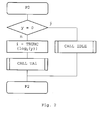
- FIG. 2 shows a flow diagram of a second subprocess P2.
- Figure 3 shows a flow chart of a first to nth Subtask TA1..TAn and an empty function IDLE.
- the first step is the first to nth subtasks TA1..TAn specific tasks performed.
- a second step determines the time interval dT, after the sequence of which calls the corresponding subtask again should be.
- the subfunction Called SETBIT which also the last one Forms the first to nth subtasks TA1..TAn.
- the idle function IDLE is simply simplified Wait function performed with a defined waiting time.
- IDLE More complex tasks for the empty function are also conceivable IDLE.
- Figure 4 shows the sequence of the sub-function SETBIT.
- the time interval dT is added to the content of row i of a fourth memory cell CT.
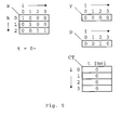
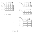
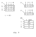
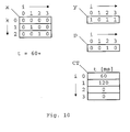
- FIG. 5 comprises a first storage device x, which is made up of M rows with N memory cells each, one second memory device y, which consists of N memory cells is constructed and a third storage device p, which is also made up of N memory cells.
- N gives the number of subtasks and M the number possible desired call times of the subtasks TA within of a cycle.
- a memory cell can have states 0 and accept 1.
- the indices of lines k run from 0 to M-1, the indices of memory cells i from 0 to N-1.
- the arrangement further comprises a fourth storage device CT, which is used to store N points in time is provided.
- the first storage device x the desired call times of the first to fourth subtask TA1..TA4 entered.
- the respective memory cells set to 1.
- the first subtask TA1 to the first possible Time within one cycle
- the second subtask TA2 at the second possible time
- the third and fourth Subtask TA3 and TA4 at the third possible time be carried out within one cycle. It follows that in line 0 of the first storage device x the digits 1000 in line 1 the numbers 0100 and in line 2 the numbers Numbers 0011 must be entered.
- the memory cells 0..N-1 of the second memory device y is set to 0.
- the third memory device p become the memory cells of those Subtasks TA set to 1 within a cycle should always be executed at the same time. in the The present example is intended for the third subtask TA3 a fixed time, the other subtasks TA on the other hand at a variable time.
- the third Storage device p is therefore identified with the numbers 0010 initialized.
- the memory cells of the fourth memory device CTs are set to 0 during initialization.
- the initialization process is now complete.
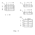
- the first subprocess P1 reads the first storage device x line by line at a constant time interval T and recurring cyclically.
- the time interval T becomes, for example set to 30ms.
- the line becomes 0 the first storage device x by means of a bitwise OR function in the second memory device y transferred.
- the bit-wise AND operation of line 0 becomes the first storage device x and the third storage device p formed and the result in row 0 of the first Transfer memory device x.
- the second subprocess P2 runs asynchronously with the first Subprocess P1 from.
- the time interval dT determines the desired recall time.
- the execution time of the first subtask TA1 is shown in the example assumed with 20ms.
- the second subprocess P2 determines the subtask TA with the highest priority level and executes this, in example shown the second subtask TA2.
- the second subtask TA2 specific ones are first again Activities carried out.
- the desired time interval dT for the second subtask TA2, dT 10ms in the example established.
- the second subtask TA2 will be executed assumed with 20ms in the example.
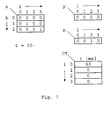
- the second sub-process P2 runs again the subtask TA with the highest priority level, in In this case, the second subtask TA2.
- the example assumes that the second subtask Activities assigned to TA2 have been completed for the time being.
- the execution time the second subtask TA2 is in the example again accepted with 20ms.
- the first storage device x therefore results in the digits 0000, 0100, 0010 and the digits 1011 for the second storage device y.
- the first storage device x is therefore structured as a ring buffer.
- the fourth storage device CT is for the smooth one Sequence of the described example of the invention
- the procedure is only mandatory insofar as in the Sub-function SETBIT a buffer for the recall time is necessary.
- the content can therefore be after execution the sub-function SETBIT can also be rejected.
- the times entered can also be used for other processes where a more precise determination of the recall time arrives because the possible division into time slices only by the length of the individual data fields of the fourth memory device CT depends, but not on the structure of the first memory device x.
Landscapes
- Engineering & Computer Science (AREA)
- Software Systems (AREA)
- Physics & Mathematics (AREA)
- General Physics & Mathematics (AREA)
- Theoretical Computer Science (AREA)
- General Engineering & Computer Science (AREA)
- Automation & Control Theory (AREA)
- Techniques For Improving Reliability Of Storages (AREA)
Abstract
Description
- bei dem die Teilaufgaben sequentiell und jeweils unterbrechungsfrei ausgeführt werden,
- bei dem in einer ersten Speichereinrichtung Informationen über den gewünschten Startzeitpunkt der einzelnen Teilaufgaben gespeichert werden und
- bei dem die Teilaufgaben anhand der in der ersten Speichereinrichtung gespeicherten Informationen entsprechend dem gewünschten Startzeitpunkt und der Prioritätsstufe der jeweiligen Teilaufgabe ausgeführt werden.
- wenn die Prioritätsstufen der Teilaufgaben mittels einer binären Zahl gespeichert werden,
- wenn diese binäre Zahl zumindest ebenso viele Stellen aufweist, wie Teilaufgaben vorhanden sind und
- wenn dem Stellenwert einer Ziffer dieser binären Zahl jeweils eine Prioritätsstufe zugeordnet wird.
- die erste Speichereinrichtung als Ringspeicher organisiert wird und
- diese erste Speichereinrichtung zyklisch zu festgelegten Zeitpunkten ausgelesen wird.
- wenn für die Steuerung ein erster Teilprozess und ein zweiter Teilprozess vorgesehen wird,
- wenn der erste Teilprozess asynchron zum zweiten Teilprozess abläuft,
- wenn der erste Teilprozess die erste Speichereinrichtung zyklisch zu festgelegten Zeitpunkten ausliest und
- wenn der zweite Teilprozess die Teilaufgaben sequentiell abarbeitet.
- wenn der erste Teilprozess die erste Speichereinrichtung zyklisch zu festgelegten Zeitpunkten ausliest und die auszuführenden Teilaufgaben in eine zweite Speichereinrichtung überträgt und
- wenn der erste Teilprozess die ausgelesene Speichereinheit der ersten Speichereinrichtung bis auf die in einer dritten Speichereinrichtung markierten Teilaufgaben löscht.
- bei der diese ein Steuermodul zur Steuerung eines in mehrere Teilaufgaben gegliederten Prozesses umfasst,
- bei der Mittel zur Speicherung gewünschter Startzeitpunkte der jeweiligen Teilaufgaben vorhanden sind,
- bei der Mittel zur Speicherung der Prioritätsstufe der jeweiligen Teilaufgaben vorhanden sind,
- bei der Mittel zur Speicherung einer vorgebbaren Zeit für die Ausführung einer Teilaufgabe vorgesehen sind und
- bei der das Steuermodul Mittel zum Lesen der gewünschten Startzeitpunkte und der Prioritätsstufen der jeweiligen Teilaufgaben umfasst.
- wenn als Mittel zur Speicherung eines gewünschten Startzeitpunktes für eine Teilaufgabe und als Mittel zur Speicherung der Prioritätsstufe eine erste Speichereinrichtung vorgesehen ist,
- wenn die Speichereinrichtung aus zumindest zwei Speicherzellen aufgebaut ist,
- wenn eine Speicherzelle für die Speicherung des gewünschten Startzeitpunkts einer Teilaufgabe vorgesehen ist und
- wenn jeder Speicherzelle eine Prioritätsstufe zugeordnet ist.
- wenn als Mittel zur Speicherung eines gewünschten Startzeitpunktes für eine Teilaufgabe und als Mittel zur Speicherung der Prioritätsstufe eine erste Speichereinrichtung vorgesehen ist,
- wenn die Speichereinrichtung aus zumindest zwei Speicherzellen aufgebaut ist,
- wenn die Speicherzellen in Zeilen und Spalten organisiert sind,
- wenn jeder Zeile ein gewünschter Startzeitpunkt zugeordnet ist und
- wenn jeder Spalte eine Prioritätsstufe zugeordnet ist. Somit kann einer Teilaufgabe allein durch Eintragung in eine bestimmte Speicherzelle der ersten Speichereinrichtung eine bestimmte Prioritätsstufe und ein gewünschter Startzeitpunkt zugeordnet werden. Diese Variante zeichnet sich daher durch besonders effizienten Ausnutzung der eingesetzten Ressourcen aus. Vorteilhaft ist auch bei dieser Variante die erste Speichereinrichtung als Ringspeicher ausgebildet.
Claims (10)
- Verfahren zur Steuerung eines Prozesses, wobeidadurch gekennzeichnet,der Prozess in mehrere Teilaufgaben gegliedert ist unddiesen Teilaufgaben verschiedene Prioritätsstufen zugewiesen sind,dass die Teilaufgaben TA sequentiell und jeweils unterbrechungsfrei ausgeführt werden,dass in einer ersten Speichereinrichtung x Informationen über den gewünschten Startzeitpunkt der einzelnen Teilaufgaben TA gespeichert werden unddass die Teilaufgaben TA anhand der in der ersten Speichereinrichtung x gespeicherten Informationen entsprechend dem gewünschten Startzeitpunkt und der Prioritätsstufe der jeweiligen Teilaufgabe ausgeführt werden.
- Verfahren nach Anspruch 1, dadurch gekennzeichnet,dass die erste Speichereinrichtung x als Ringspeicher organisiert wird unddass diese erste Speichereinrichtung x zyklisch zu festgelegten Zeitpunkten ausgelesen wird.
- Verfahren nach einem der Ansprüche 1 bis 2, dadurch gekennzeichnet, dass während der Ausführung einer Teilaufgabe TA die gewünschte Aufrufzeit einer Teilaufgabe TA, insbesondere der ausgeführten Teilaufgabe TA, ermittelt wird.
- Verfahren nach einem der Ansprüche 1 bis 3, dadurch gekennzeichnet,dass für die Steuerung ein erster Teilprozess P1 und ein zweiter Teilprozess P2 vorgesehen ist,dass der erste Teilprozess P1 asynchron zum zweiten Teilprozess P2 abläuft,dass der erste Teilprozess P1 die erste Speichereinrichtung x zyklisch zu festgelegten Zeitpunkten ausliest unddass der zweite Teilprozess P2 die Teilaufgaben TA sequentiell abarbeitet.
- Verfahren nach Anspruch 4, dadurch gekennzeichnet,dass der erste Teilprozess P1 die erste Speichereinrichtung x zyklisch zu festgelegten Zeitpunkten ausliest und die auszuführenden Teilaufgaben TA in eine zweite Speichereinrichtung y überträgt unddass der erste Teilprozess P1 die ausgelesene Speichereinheit der ersten Speichereinrichtung x bis auf die in einer dritten Speichereinrichtung p markierten Teilaufgaben TA löscht.
- Verfahren nach Anspruch 5, dadurch gekennzeichnet, dass der zweite Teilprozess P2 die zweite Speichereinrichtung y ausliest und die Teilaufgabe TA mit der höchsten Priorität ausführt, wenn die zweite Speichereinrichtung y nicht leer ist und eine Leerfunktion IDLE aufruft, wenn die zweite Speichereinrichtung x leer ist.
- Anordnung zur Durchführung des Verfahrens nach einem der Ansprüche 1 bis 6,
dadurch gekennzeichnet,dass diese ein Steuermodul zur Steuerung eines in mehrere Teilaufgaben TA gegliederten Prozesses umfasst,dass Mittel zur Speicherung gewünschter Startzeitpunkte der jeweiligen Teilaufgaben TA vorhanden sind,dass Mittel zur Speicherung der Prioritätsstufe der jeweiligen Teilaufgaben TA vorhanden sind unddass das Steuermodul Mittel zum Lesen der gewünschten Startzeitpunkte und der Prioritätsstufen der jeweiligen Teilaufgaben TA umfasst. - Anordnung nach Anspruch 7, dadurch gekennzeichnet,dass als Mittel zur Speicherung eines gewünschten Startzeitpunktes für eine Teilaufgabe TA und als Mittel zur Speicherung der Prioritätsstufe eine erste Speichereinrichtung x vorgesehen ist,dass diese erste Speichereinrichtung x aus zumindest zwei Speicherzellen aufgebaut ist,dass eine Speicherzelle für die Speicherung des gewünschten Startzeitpunkts einer Teilaufgabe TA vorgesehen ist unddass jeder Speicherzelle eine Prioritätsstufe zugeordnet ist.
- Anordnung nach einem der Ansprüche 7 bis 8, dadurch gekennzeichnet,dass als Mittel zur Speicherung eines gewünschten Startzeitpunktes für eine Teilaufgabe TA und als Mittel zur Speicherung der Prioritätsstufe eine erste Speichereinrichtung x vorgesehen ist,dass diese erste Speichereinrichtung x aus zumindest zwei Speicherzellen aufgebaut ist,dass die Speicherzellen in Zeilen k und Spalten i organisiert sind,dass jeder Zeile k ein gewünschter Startzeitpunkt zugeordnet ist unddass jeder Spalte i eine Prioritätsstufe zugeordnet ist.
- Anordnung nach einem der Ansprüche 7 bis 9, dadurch gekennzeichnet, dass eine dritte Speichereinrichtung p zur Speicherung zyklisch wiederkehrender gewünschter Startzeitpunkte der Teilaufgaben TA vorhanden ist.
Priority Applications (1)
| Application Number | Priority Date | Filing Date | Title |
|---|---|---|---|
| EP20010106368 EP1243987B1 (de) | 2001-03-19 | 2001-03-19 | Verfahren und Anordnung zur Steuerung der Ausführung von Teilaufgaben eines Prozesses |
Applications Claiming Priority (1)
| Application Number | Priority Date | Filing Date | Title |
|---|---|---|---|
| EP20010106368 EP1243987B1 (de) | 2001-03-19 | 2001-03-19 | Verfahren und Anordnung zur Steuerung der Ausführung von Teilaufgaben eines Prozesses |
Publications (2)
| Publication Number | Publication Date |
|---|---|
| EP1243987A1 true EP1243987A1 (de) | 2002-09-25 |
| EP1243987B1 EP1243987B1 (de) | 2011-10-05 |
Family
ID=8176781
Family Applications (1)
| Application Number | Title | Priority Date | Filing Date |
|---|---|---|---|
| EP20010106368 Expired - Lifetime EP1243987B1 (de) | 2001-03-19 | 2001-03-19 | Verfahren und Anordnung zur Steuerung der Ausführung von Teilaufgaben eines Prozesses |
Country Status (1)
| Country | Link |
|---|---|
| EP (1) | EP1243987B1 (de) |
Cited By (2)
| Publication number | Priority date | Publication date | Assignee | Title |
|---|---|---|---|---|
| WO2003069424A3 (de) * | 2002-02-18 | 2004-12-29 | Daimler Chrysler Ag | Reaktionszeit-beschränkung eines software-prozesses |
| EP3757525A1 (de) * | 2019-06-24 | 2020-12-30 | Pepperl+Fuchs Gmbh | Sensor und verfahren zum betreiben eines sensors |
Citations (2)
| Publication number | Priority date | Publication date | Assignee | Title |
|---|---|---|---|---|
| DE19500957A1 (de) * | 1994-07-19 | 1996-01-25 | Bosch Gmbh Robert | Verfahren zur Steuerung von technischen Vorgängen oder Prozessen |
| DE19527541A1 (de) * | 1995-07-27 | 1997-01-30 | Siemens Ag | Vorrichtung zur Erzeugung von Steuersignalen |
-
2001
- 2001-03-19 EP EP20010106368 patent/EP1243987B1/de not_active Expired - Lifetime
Patent Citations (2)
| Publication number | Priority date | Publication date | Assignee | Title |
|---|---|---|---|---|
| DE19500957A1 (de) * | 1994-07-19 | 1996-01-25 | Bosch Gmbh Robert | Verfahren zur Steuerung von technischen Vorgängen oder Prozessen |
| DE19527541A1 (de) * | 1995-07-27 | 1997-01-30 | Siemens Ag | Vorrichtung zur Erzeugung von Steuersignalen |
Cited By (2)
| Publication number | Priority date | Publication date | Assignee | Title |
|---|---|---|---|---|
| WO2003069424A3 (de) * | 2002-02-18 | 2004-12-29 | Daimler Chrysler Ag | Reaktionszeit-beschränkung eines software-prozesses |
| EP3757525A1 (de) * | 2019-06-24 | 2020-12-30 | Pepperl+Fuchs Gmbh | Sensor und verfahren zum betreiben eines sensors |
Also Published As
| Publication number | Publication date |
|---|---|
| EP1243987B1 (de) | 2011-10-05 |
Similar Documents
| Publication | Publication Date | Title |
|---|---|---|
| DE4135749B4 (de) | Prozessormodul für eine programmierbare Steuerung mit einer intelligenten Funktionsmodulschnittstelle | |
| EP0655682B1 (de) | Recheneinheit mit mehreren ausführbaren Tasks | |
| DE1549532C2 (de) | Unterbrechungs-Direktorschalrwerk für eine Datenverarbeitungsanlage mit mehreren Rechenanlagen und mehreren perpheren Geräten | |
| DE3300261C2 (de) | ||
| DE3300263C2 (de) | ||
| DE1499182C3 (de) | Datenspeichersystem | |
| DE69839194T2 (de) | Gerät und verfahren zum initieren hardwarevorrangsmanagement durch softwarekontrollierten registerzugriff | |
| DE1499200A1 (de) | Datenverarbeitungsanlage mit vorranggesteuerter Programmunterbrechung | |
| DE2930441C2 (de) | Anzeigeeinrichtung zur wahlweisen dynamischen oder statischen Anzeige | |
| DE2054830C3 (de) | Informationsverarbeitungsanlage mit Mitteln zum Zugriff zu Speicher-Datenfeldern variabler Länge | |
| DE1200581B (de) | Programmunterbrechungssystem fuer eine elektronische Rechenmaschine | |
| DE2722124A1 (de) | Anordnung zum feststellen des prioritaetsranges in einem dv-system | |
| DE68929080T2 (de) | Anordnung zum Speichern von Informationen für einen Datenanbieterprozessor | |
| DE3400723A1 (de) | Vektorprozessor | |
| DE19957594B4 (de) | Verfahren zum Synchronisieren von threads eines Computerprogramms | |
| DE4321774C1 (de) | Verfahren zum Aktualisieren eines Systemprogramms in einer Vermittlungseinrichtung | |
| DE10063915B4 (de) | Informationsverarbeitungsgerät, das eine Mehrzweckverarbeitung und Transaktionsverarbeitung ausführt | |
| DE2336333A1 (de) | Elektronischer tischrechner mit in mos-technik ausgefuehrter logischer schaltung | |
| DE2745204A1 (de) | Mikroprogramm-leitwerk fuer eine datenverarbeitungsanlage | |
| EP0419723B1 (de) | Verfahren und Unterbrechungssteuerung zur Behandlung von Unterbrechungsanforderungen bei Ein-/Ausgabeoperationen in einem virtuellen Maschinensystem | |
| EP0466948A1 (de) | Kommunikationssystem mit einem der zentralen Steuerung dienenden Multiprozessorsystem | |
| EP1243987B1 (de) | Verfahren und Anordnung zur Steuerung der Ausführung von Teilaufgaben eines Prozesses | |
| DE3854641T2 (de) | Arbeitstellen-Steuergerät zum Schreiben auf einem vollen Bildschirm und zum teilweise Schreiben auf einem Bildschirm. | |
| DE1296427B (de) | Datenbearbeitungssystem | |
| DE1212748B (de) | Datenverarbeitende Maschine mit Programmunterbrechung |
Legal Events
| Date | Code | Title | Description |
|---|---|---|---|
| PUAI | Public reference made under article 153(3) epc to a published international application that has entered the european phase |
Free format text: ORIGINAL CODE: 0009012 |
|
| AK | Designated contracting states |
Kind code of ref document: A1 Designated state(s): AT BE CH CY DE DK ES FI FR GB GR IE IT LI LU MC NL PT SE TR |
|
| AX | Request for extension of the european patent |
Free format text: AL;LT;LV;MK;RO;SI |
|
| 17P | Request for examination filed |
Effective date: 20030107 |
|
| AKX | Designation fees paid |
Designated state(s): DE FR GB IT |
|
| 17Q | First examination report despatched |
Effective date: 20070726 |
|
| RIC1 | Information provided on ipc code assigned before grant |
Ipc: G05B 19/042 20060101AFI20110119BHEP Ipc: G06F 9/48 20060101ALI20110119BHEP |
|
| GRAP | Despatch of communication of intention to grant a patent |
Free format text: ORIGINAL CODE: EPIDOSNIGR1 |
|
| RAP1 | Party data changed (applicant data changed or rights of an application transferred) |
Owner name: SIEMENS ENTERPRISE COMMUNICATIONS GMBH & CO. KG |
|
| GRAS | Grant fee paid |
Free format text: ORIGINAL CODE: EPIDOSNIGR3 |
|
| GRAA | (expected) grant |
Free format text: ORIGINAL CODE: 0009210 |
|
| AK | Designated contracting states |
Kind code of ref document: B1 Designated state(s): DE FR GB IT |
|
| REG | Reference to a national code |
Ref country code: GB Ref legal event code: FG4D Free format text: NOT ENGLISH |
|
| REG | Reference to a national code |
Ref country code: DE Ref legal event code: R096 Ref document number: 50115968 Country of ref document: DE Effective date: 20111201 |
|
| PLBE | No opposition filed within time limit |
Free format text: ORIGINAL CODE: 0009261 |
|
| STAA | Information on the status of an ep patent application or granted ep patent |
Free format text: STATUS: NO OPPOSITION FILED WITHIN TIME LIMIT |
|
| 26N | No opposition filed |
Effective date: 20120706 |
|
| REG | Reference to a national code |
Ref country code: DE Ref legal event code: R097 Ref document number: 50115968 Country of ref document: DE Effective date: 20120706 |
|
| REG | Reference to a national code |
Ref country code: DE Ref legal event code: R082 Ref document number: 50115968 Country of ref document: DE Representative=s name: FRITZSCHE PATENT, DE |
|
| REG | Reference to a national code |
Ref country code: DE Ref legal event code: R081 Ref document number: 50115968 Country of ref document: DE Owner name: UNIFY GMBH & CO. KG, DE Free format text: FORMER OWNER: SIEMENS ENTERPRISE COMMUNICATIONS GMBH & CO. KG, 81379 MUENCHEN, DE Effective date: 20131112 Ref country code: DE Ref legal event code: R082 Ref document number: 50115968 Country of ref document: DE Representative=s name: FRITZSCHE PATENT, DE Effective date: 20131112 Ref country code: DE Ref legal event code: R081 Ref document number: 50115968 Country of ref document: DE Owner name: UNIFY GMBH & CO. KG, DE Free format text: FORMER OWNER: SIEMENS AKTIENGESELLSCHAFT, 80333 MUENCHEN, DE Effective date: 20111010 Ref country code: DE Ref legal event code: R082 Ref document number: 50115968 Country of ref document: DE Representative=s name: FRITZSCHE PATENTANWAELTE, DE Effective date: 20131112 |
|
| REG | Reference to a national code |
Ref country code: FR Ref legal event code: CD Owner name: UNIFY GMBH & CO. KG, DE Effective date: 20150209 |
|
| REG | Reference to a national code |
Ref country code: FR Ref legal event code: PLFP Year of fee payment: 15 |
|
| PGFP | Annual fee paid to national office [announced via postgrant information from national office to epo] |
Ref country code: IT Payment date: 20150326 Year of fee payment: 15 |
|
| PGFP | Annual fee paid to national office [announced via postgrant information from national office to epo] |
Ref country code: GB Payment date: 20150324 Year of fee payment: 15 Ref country code: FR Payment date: 20150319 Year of fee payment: 15 |
|
| REG | Reference to a national code |
Ref country code: DE Ref legal event code: R082 Ref document number: 50115968 Country of ref document: DE Representative=s name: FRITZSCHE PATENTANWAELTE, DE Ref country code: DE Ref legal event code: R081 Ref document number: 50115968 Country of ref document: DE Owner name: UNIFY GMBH & CO. KG, DE Free format text: FORMER OWNER: UNIFY GMBH & CO. KG, 81379 MUENCHEN, DE |
|
| GBPC | Gb: european patent ceased through non-payment of renewal fee |
Effective date: 20160319 |
|
| REG | Reference to a national code |
Ref country code: FR Ref legal event code: ST Effective date: 20161130 |
|
| PG25 | Lapsed in a contracting state [announced via postgrant information from national office to epo] |
Ref country code: FR Free format text: LAPSE BECAUSE OF NON-PAYMENT OF DUE FEES Effective date: 20160331 Ref country code: GB Free format text: LAPSE BECAUSE OF NON-PAYMENT OF DUE FEES Effective date: 20160319 |
|
| PG25 | Lapsed in a contracting state [announced via postgrant information from national office to epo] |
Ref country code: IT Free format text: LAPSE BECAUSE OF NON-PAYMENT OF DUE FEES Effective date: 20160319 |
|
| PGFP | Annual fee paid to national office [announced via postgrant information from national office to epo] |
Ref country code: DE Payment date: 20180322 Year of fee payment: 18 |
|
| REG | Reference to a national code |
Ref country code: DE Ref legal event code: R119 Ref document number: 50115968 Country of ref document: DE |
|
| PG25 | Lapsed in a contracting state [announced via postgrant information from national office to epo] |
Ref country code: DE Free format text: LAPSE BECAUSE OF NON-PAYMENT OF DUE FEES Effective date: 20191001 |