EP1243886A1 - Echangeur thermique haute temperature a ailette plate - Google Patents
Echangeur thermique haute temperature a ailette plate Download PDFInfo
- Publication number
- EP1243886A1 EP1243886A1 EP00985871A EP00985871A EP1243886A1 EP 1243886 A1 EP1243886 A1 EP 1243886A1 EP 00985871 A EP00985871 A EP 00985871A EP 00985871 A EP00985871 A EP 00985871A EP 1243886 A1 EP1243886 A1 EP 1243886A1
- Authority
- EP
- European Patent Office
- Prior art keywords
- temperature fluid
- low
- temperature
- heat exchanger
- channels
- Prior art date
- Legal status (The legal status is an assumption and is not a legal conclusion. Google has not performed a legal analysis and makes no representation as to the accuracy of the status listed.)
- Withdrawn
Links
Images


Classifications
-
- F—MECHANICAL ENGINEERING; LIGHTING; HEATING; WEAPONS; BLASTING
- F28—HEAT EXCHANGE IN GENERAL
- F28F—DETAILS OF HEAT-EXCHANGE AND HEAT-TRANSFER APPARATUS, OF GENERAL APPLICATION
- F28F3/00—Plate-like or laminated elements; Assemblies of plate-like or laminated elements
- F28F3/02—Elements or assemblies thereof with means for increasing heat-transfer area, e.g. with fins, with recesses, with corrugations
- F28F3/025—Elements or assemblies thereof with means for increasing heat-transfer area, e.g. with fins, with recesses, with corrugations the means being corrugated, plate-like elements
-
- F—MECHANICAL ENGINEERING; LIGHTING; HEATING; WEAPONS; BLASTING
- F28—HEAT EXCHANGE IN GENERAL
- F28D—HEAT-EXCHANGE APPARATUS, NOT PROVIDED FOR IN ANOTHER SUBCLASS, IN WHICH THE HEAT-EXCHANGE MEDIA DO NOT COME INTO DIRECT CONTACT
- F28D9/00—Heat-exchange apparatus having stationary plate-like or laminated conduit assemblies for both heat-exchange media, the media being in contact with different sides of a conduit wall
- F28D9/0062—Heat-exchange apparatus having stationary plate-like or laminated conduit assemblies for both heat-exchange media, the media being in contact with different sides of a conduit wall the conduits for one heat-exchange medium being formed by spaced plates with inserted elements
- F28D9/0068—Heat-exchange apparatus having stationary plate-like or laminated conduit assemblies for both heat-exchange media, the media being in contact with different sides of a conduit wall the conduits for one heat-exchange medium being formed by spaced plates with inserted elements with means for changing flow direction of one heat exchange medium, e.g. using deflecting zones
-
- F—MECHANICAL ENGINEERING; LIGHTING; HEATING; WEAPONS; BLASTING
- F28—HEAT EXCHANGE IN GENERAL
- F28F—DETAILS OF HEAT-EXCHANGE AND HEAT-TRANSFER APPARATUS, OF GENERAL APPLICATION
- F28F2250/00—Arrangements for modifying the flow of the heat exchange media, e.g. flow guiding means; Particular flow patterns
- F28F2250/10—Particular pattern of flow of the heat exchange media
- F28F2250/102—Particular pattern of flow of the heat exchange media with change of flow direction
-
- F—MECHANICAL ENGINEERING; LIGHTING; HEATING; WEAPONS; BLASTING
- F28—HEAT EXCHANGE IN GENERAL
- F28F—DETAILS OF HEAT-EXCHANGE AND HEAT-TRANSFER APPARATUS, OF GENERAL APPLICATION
- F28F2265/00—Safety or protection arrangements; Arrangements for preventing malfunction
- F28F2265/26—Safety or protection arrangements; Arrangements for preventing malfunction for allowing differential expansion between elements
Definitions
- the present invention relates to the improvement of a plate fin heat exchanger for a high temperature, for example, conducting heat exchange between combustion exhaust gases and the air. More specifically, the present invention relates to a plate fin heat exchanger for a high temperature with a structure in which elements obtained by soldering fins to both tube plate surfaces of the channel for low-temperature air are stacked and arranged via spacer bars and in which a tubular duct for high-temperature fluid can be used by itself as a heat exchanger container, this heat exchanger demonstrating excellent endurance and high heat exchange efficiency when used under severe conditions, for example, as a regenerator of a micro gas turbine power generator.
- Micro gas turbine power generators have recently attracted attention and found practical use as emergency private power generators or medium-and small-scale distributed power sources.
- Gas turbines have a structure simpler than that of other internal combustion engines, can be produced on a mass scale, are easy to maintain and inspect, and operate at a low NOx level.
- Micro gas turbine power generators of the next generation typically employ a structure of a single-shaft regeneration cycle gas turbine to improve the total power generation efficiency.
- a compressor, a turbine, and a generator are arranged on one shaft, combustion gases from a combustion chamber rotate the turbine, and then heat exchange is conducted in a heat exchanger with the air that passed the compressor.
- the power generators of this type decrease, even if to a small degree, the loss of combustion gas energy and have a thermal conversion efficiency equal to, or better than that of conventional power generators employing diesel engines.
- micro gas turbine power generators are required to endure a large number of start/stop cycles and also to have the improved operation start-up characteristic immediately after they are turned on and to supply immediately the necessary power. This requirement is obvious for emergency situations, but is also valid for applications of such power generators as distributed power sources.
- plate fin heat exchangers used for heat exchange between combustion gases and compressed air are required to demonstrate an excellent heat exchange efficiency and to retain the attained heat exchange efficiency, while maintaining endurance sufficient to withstand vary intense heat input, in particular non-uniform temperature distribution inside the fluid channels and extreme variations of thermal load.
- the inventors have conducted a comprehensive study of structures making it possible to lessen thermal stresses in plate fin heat exchangers, for example, caused by non-uniform temperature distribution inside fluid channels and in the entire apparatus occurring when high-temperature combustion gas flows therein.
- the results obtained demonstrated that usually all of the fins located inside the high-temperature channels were soldered to low-temperature channels, but as shown in Fig. 1B, making all of the fins located inside the high-temperature channels independent for each low-temperature channels, rather than soldering them, lessened thermal stresses, greatly increased the endurance and also allowed for a transition to a modular structure, reduced the number of soldering operations, and increased mass productivity.
- the inventors have also found that using non-directional distributors containing no corrugation fins and the like in the low-temperature channels in the above-described structure makes it possible to prevent one-side flow in the heat exchange unit, and that appropriately providing a shielding cover on the front surface of the low-temperature channel facing the inlet opening of high-temperature channel additionally increases endurance, without exposing the soldered portions of low-temperature channel to high-temperature fluid.
- the first invention provides a plate fin heat exchanger for a high temperature, in which channels for low-temperature fluid and channels for high-temperature fluid are disposed in stacks and form a core independently for each channel for low-temperature fluid.
- a structure in which the fins forming a channel for high-temperature fluid are fixed to at least one of a pair of tube plates forming the channels for low-temperature fluid as an element and forming a core by disposing a plurality of such elements inside a container such as a duct for high-temperature fluid makes it possible to provide plate fin heat exchangers with highly durable structure for high temperature, such heat exchangers being suitable for mass production.
- core assembly elements are produced by decreasing the size of fins located inside the high-temperature channels, fixing them to the low-temperature channel, and arranging small spacer bars in places where no fins are provided, and if those elements are assembled by stacking conducted, for example, by seal welding the spacer bars to each other.
- the second invention relates to a plate fin heat exchanger for a high temperature with a structure in which channels for low-temperature fluid and channels for high-temperature fluid are disposed in stacks and form a core independently for each channel for low-temperature fluid by using core assembly elements in which spacer bars and fins forming the channels for high-temperature fluid are fixed to at least one of a pair of tube plates forming the channels for low-temperature fluid.
- a heat exchange system with a very good heat recovery efficiency can be constructed in which waste heat recovery can be conducted, for example, by using the upstream heat exchanger as a regenerator in a micro gas turbine power generator and using the downstream heat exchanger as a steam and/or hot water generator.
- the third invention relates to a plate fin heat exchanger for a high temperature, in which a tubular duct for high-temperature fluid serves by itself as a heat exchanger container and channels for low-temperature fluid and channels for high-temperature fluid are disposed in stacks and form a core independently for each channel for low-temperature fluid by using core assembly elements in which fins forming the channels for high-temperature fluid, and optionally space bars, are fixed to at least one of a pair of tube plates forming the channels for low-temperature fluid, wherein at least one separate heat exchanger conducting heat exchange with high-temperature fluid is additionally disposed downstream of the heat exchangers located inside the duct.
- the inventors have assumed a double-wall tubular system structure in which heat exchangers are disposed in a ring-like fashion on the outer periphery of a turbine in a micro gas turbine power generator and are used as regenerators conducting heat exchange by causing the exhaust gases from the turbine to make a U turn and have conducted a comprehensive study of effective arrangement of the above-described core units.
- the fourth invention relates to a plate fin heat exchanger for a high temperature, in which a plurality of core units are disposed radially inside a cylindrical body serving as a channel for high-temperature fluid or between a cylindrical body and an inner tube arranged inside the cylindrical body, those core units being formed by disposing channels for low-temperature fluid and channels for high-temperature fluid in stacks independently for each channel for low-temperature fluid by using core assembly elements in which fins forming the channels for high-temperature fluid, and optionally spacer bars, are fixed to at least one of a pair of tube plates forming the channels for low-temperature fluid, wherein
- FIG. 1A relates to counter-flow heat exchange between a high-temperature fluid and a low-temperature fluid.
- the high-temperature fluid H passes through a core 2 of a heat exchanger 1 from the front to the rear part thereof, whereas the low-temperature fluid L flows into the heat exchanger 1 through the side surface in the rear part thereof and flows out from the side surface in the front part thereof.
- the core 2 of heat exchanger 1 has a structure in which high-temperature fluid channels 4 and low-temperature fluid channels 5 are stacked alternately inside a container 3.
- the low-temperature fluid channel 5, as shown in FIG. 1B and FIG. 2, has a configuration in which a corrugation fin 5b is sandwiched between two tube plates 5a, 5a and those components are brazed and integrated so that the peripheral portions are closed with spacer bars 5c.
- a spacer bar 5d on one end surface side is made short to form a fluid inlet opening 6 and a fluid outlet opening 7 and fluid distributor portions 5e, 5f serve as non-directional distributors having no fins disposed therein.
- corrugation fins 4a, 4b are brazed to respective outer surfaces of the two tube plates 5a, 5a of low-temperature fluid channel 5.
- the above-described low-temperature fluid channels 5 are disposed with the prescribed spacing inside the container 3 containing the core 2 of heat exchanger 1.
- high-temperature fluid channels 4 are formed by the corrugation fins 4a, 4b.
- the fluid inlet openings 6 and outlet openings 7 of low-temperature fluid channels 5 are cantilever supported on the side surface of the box-like container 3, and the low-temperature fluid channels 5 are disposed inside the container 3 at a spacing preventing the corrugation fins 4a, 4b from abutting each other.
- the side of container 3 where the inlet openings of high-temperature fluid channels 4 are located is intensely heated.
- the high-temperature fluid channels 4 are formed by corrugation fins 4a, 4b provided on the outer surface of low-temperature fluid channels 5. Those fins are not restricted inside the high-temperature fluid channels 4 and even when they are intensely heated, they do not accumulate thermal stresses and can effectively conduct the heat of high-temperature fluid H into the low-temperature fluid channels 5.
- the low-temperature fluid L flowing in from a non-directional distributor portion 5e can participate in counter-flow heat exchange with the high-temperature fluid H, without a drift flow, and can flow out via the non-directional distributor portion 5f from the fluid outlet opening 7 after being heated to a high temperature.
- the corrugation fins 4a, 4b of high-temperature fluid channels 4 are exposed to a high temperature, thermal stresses are not accumulated in the low-temperature fluid channel 5.
- intense heating of the low-temperature fluid channels 5 themselves also causes no accumulation of thermal stresses because of the cantilever support structure.
- the rigidity of distributor portions 5e, 5f can be increased by using a structure in which the tube plates are provided with dimples and protruding portions of the dimples are abutted against and joined to each other inside the channels.
- FIG. 4 relates to counter-flow heat exchange between a high-temperature fluid and a low-temperature fluid.
- the high-temperature fluid H passes through a core 2 of heat exchanger 1 from the front to the rear part thereof, whereas the low-temperature fluid L flows into the heat exchanger 1 through the side surface in the rear part thereof and flows out from the side surface in the front part thereof.
- the core 2 of heat exchanger 1 has a structure in which high-temperature fluid channels 4 and low-temperature fluid channels 5 are stacked alternately inside a container 3.
- the low-temperature fluid channel 5, as shown in FIG. 5 and FIG. 6, has a configuration in which a corrugation fin 5b is sandwiched between two tube plates 5a, 5a and those components are brazed and integrated so that the peripheral portions are closed with spacer bars 5c.
- a spacer bar 5d on one end surface side is made short to form a fluid inlet opening 6 and a fluid outlet opening 7, and triangular fins are disposed in the fluid distributor portions 5e, 5f to form distribution channels.
- corrugation fins 4a, 4b are brazed to respective outer surfaces of the two tube plates 5a, 5a of low-temperature fluid channel 5.
- the corrugation fins 4a, 4b are disposed in the positions facing the corrugation fins 5g which are the main fin components, except the distributor portions 5e, 5f located inside the low-temperature fluid channel 5, and short spacer bars 4b are fixed in four places mainly serving as the end portions of respective positions of distributor portions 5e, 5f.
- low-temperature fluid channels 5 are cantilever supported, being secured only to the right side surface of the box-like container 3, as shown in the figure, and the spacer bar 4b side on the left side, as shown in the figure, is not fixed. Furthermore, low-temperature fluid channels 5 are disposed inside the container 3 at a spacing preventing the corrugation fins 4a, 4b from abutting each other. Header tanks (not shown in the figure) are fixedly disposed in the fluid inlet opening 6 and outlet opening 7 of container 3.
- the side of container 3 where the inlet openings of high-temperature fluid channels 4 are located is intensely heated.
- the high-temperature fluid channels 4 are formed by corrugation fins 4a, 4b provided in the central portion of the outer surface of low-temperature fluid channels 5. Those fins are not restricted inside the high-temperature fluid channels 4 and even when they are intensely heated, they do not accumulate thermal stresses and can effectively conduct the heat of high-temperature fluid H into the low-temperature fluid channels 5.
- the low-temperature fluid L flowing in from a distributor portion 5e can participate in counter-flow heat exchange with the high-temperature fluid H, without a drift flow, and can flow out via the non-directional distributor portion 5f from the fluid outlet opening 7 after being heated to a high temperature.
- the corrugation fins 4a, 4b of high-temperature fluid channels 4 are not located in the positions corresponding to the distributor portions 5e, 5f, and even if they are exposed to a high temperature, thermal stresses are not accumulated in the low-temperature fluid channel 5.
- intense heating of the low-temperature fluid channels 5 themselves also causes no accumulation of thermal stresses because of the cantilever support structure.
- the intense heat input observed when the high-temperature fluid H flows in at a high speed can be relieved by attaching shielding covers of various types to the front surface of the low-temperature fluid channel 5 facing the inlet opening of high-temperature fluid channel 4 in the above-described Structure Example 1 and Structure Example 2.
- shielding covers of various types can be attached, or a thermal insulating member can be attached, or the tube plate of low-temperature fluid channel 5 can be extended and bent.
- means for making the low-temperature fluid channels independent from each other can have a variety of structures other than the above-one structures.
- a structure in which corrugation fins are provided only on one surface of low-temperature fluid channels, a structure with cross-flow heat exchange, and a structure in which the duct of the high-temperature fluid serves by itself as the heat exchanger can be used.
- a variety of other dispositions for example, a combination of counter flow and cross flow, can be employed for stacking the low-temperature fluid channels and high-temperature fluid channels in the core, and the specific disposition can be appropriately selected according to the type of fluid or temperature.
- heat exchanger no limitation is placed on the material of heat exchanger.
- heat resistance if heat resistance is required, then well-known Fe-based, Ni-based, or Co-based heat-resistance alloys can be used.
- austenitic heat-resistance steels, Co3Ti, Ni3Al, and stainless steels with an Al content of no more than 10 wt.% can be used. The same is true for the below-described structure examples.
- FIG. 1A Another example of the structure of the plate fin heat exchanger for a high temperature in accordance with the present invention will be explained below with reference to FIGS. 7 and 8.
- This example relates to counter-flow heat exchange between a high-temperature fluid H and a low-temperature fluid.
- the high-temperature fluid H passes through a core 2 of heat exchanger 1
- the side of heat exchanger 1 which is upstream of high-temperature fluid H is a pre-stage heat exchanger 1a
- the downstream side is a post-stage heat exchanger 1b
- heat exchange is conducted in two stages.
- the rear-stage heat exchanger 1b constitutes separate heat exchangers 1b1, 1b2 on the upper and lower side.
- the length of post-stage heat exchanger 1b is represented to be equal to that of front-side heat exchanger 1a, but it can obviously be appropriately selected, for example, to be less or more depending of specifications of heat exchangers and required performance.
- the pre-stage heat exchanger 1a positioned upstream of heat exchanger 1 has a structure such that a low-temperature fluid L, which is composed of the air, flows in from the rear side surface of pre-stage heat exchanger 1a and flows out from the side surface in the front side thereof, with respect to a high-temperature fluid H, such as high-temperature exhaust gases, flowing from the front to the rear portion.
- a low-temperature fluid L which is composed of the air
- the core 2 of pre-stage heat exchanger 1a has a structure in which the high-temperature fluid channels 4 and low-temperature fluid channels 5 are stacked alternately inside the container 3, as shown in FIG. 5.
- the low-temperature fluid channel 5, as shown in FIG. 6, has a configuration such that a corrugation fin 5g is sandwiched between two tube plates 5a, 5a, and those components are brazed and integrated so that the peripheral portions are closed with spacer bars 5c.
- a spacer bar 5d on one end surface side is made short to form a fluid inlet opening 6 and a fluid outlet opening 7 and triangular fins are disposed in the fluid distributor portions 5e, 5f to form distribution channels.
- corrugation fins 4a, 4b are brazed to respective outer surfaces of the two tube plates 5a, 5a of low-temperature fluid channel 5.
- the corrugation fins 4a, 4b are disposed in the positions facing the main fin components 5g, except the distributor portions 5e, 5f located inside the low-temperature fluid channel 5, and short spacer bars 4c are fixed in four places mainly serving as the end portions of respective positions of distributor portions 5e, 5f.
- low-temperature fluid channels 5 are cantilever supported, being secured only to the right side surface of the box-like container 3, as shown in the figure, and the spacer bar 4 side on the left side, as shown in the figure, is not fixed. Furthermore, low-temperature fluid channels 5 are disposed inside the container 3 at a spacing preventing the corrugation fins 4a, 4b from abutting each other. Header tanks (not shown in the figure) are fixedly disposed in the fluid inlet opening 6 and outlet opening 7 of container 3.
- the side of container 3 where the inlet openings of high-temperature fluid channels 4 are located is intensely heated.
- the high-temperature fluid channels 4 are formed by corrugation fins 4a, 4a provided in the central portion of the outer surface of low-temperature fluid channels 5. Those fins are not restricted inside the high-temperature fluid channels 4 and even when they are intensely heated, they do not accumulate thermal stresses and can effectively conduct the heat of high-temperature fluid H to the low-temperature fluid channels 5.
- the low-temperature fluid L flowing in from a distributor portion 5e can participate in counter-flow heat exchange with the high-temperature fluid H, without a drift flow, and can flow out via the non-directional distributor portion 5f from the fluid outlet opening 7 after being heated to a high temperature.
- the corrugation fins 4a, 4a of high-temperature fluid channels 4 are not located in the positions corresponding to the distributor portions 5e, 5f, and even if they are exposed to a high temperature, thermal stresses are not accumulated in the low-temperature fluid channel 5.
- intense heating of the low-temperature fluid channels 5 themselves also causes no accumulation of thermal stresses because of the cantilever support structure.
- the rear-stage heat exchanger 1b basically has the same structure as the above-described pre-stage heat exchanger 1a and constitutes separate heat exchangers 1b1, 1b2 on the upper and lower side.
- the plate fin heat exchangers for a high temperature of the above-described structure shown in FIG. 2 have a common container 3, are connected in series in the direction of high-temperature fluid flow and form an upstream pre-stage heat exchanger 1a and a downstream rear-stage heat exchanger 1b.
- the inlet and outlet openings for fluid of the rear-stage heat exchanger can be further divided in the vertical direction, providing for inlet and outlet of separate fluids and forming separate heat exchangers 1b1, 1b2 on the upper and lower side.
- a large amount of water can be introduced as a low-temperature fluid L1 into the upper heat exchanger 1b1 of rear-stage heat exchanger 1b and a hot-water at the prescribed temperature can be taken out.
- a small amount of water can be introduced as a low-temperature fluid L2 into the lower heat exchanger 1b2 and steam can be taken out.
- the rear-stage heat exchanger 1b is divided in two in the width direction of container 3, as shown in FIG. 8, by using a cantilever structure, shown in FIG 1, forming separate heat exchangers, namely, a right heat exchanger and a left heat exchanger supported on respective side surfaces of container 3, and the respective different low-temperature fluid L1 and low-temperature fluid L2 can be introduced and taken out.
- a structure can be also employed in which a switchable outlet damper 8 is provided on the downstream end of container 3, making it possible to select a heat exchanger through which a high-temperature fluid H is passed.
- a switchable outlet damper 8 is provided on the downstream end of container 3, making it possible to select a heat exchanger through which a high-temperature fluid H is passed.
- the rear-stage heat exchangers 1b can be arranged not only in one stage with the separation into upper and lower heat exchangers, but also in a multistage series. Therefore, a plurality of heat exchanges can be conducted till the temperature of high-temperature fluid drops to the prescribed temperature.
- a fin-plate heat exchanger with a cantilever structure identical to that of the pre-stage heat exchangers was used for the rear-stage heat exchanger 1b.
- heat exchangers of a variety of conventional structures such as plate fin heat exchangers or tubular heat exchangers, can be selected and appropriately disposed in a common container 3 according to the required performance or specifications.
- FIG. 9 An example of the structure of the plate fin heat exchanger for a high temperature in accordance with the present invention will be explained below with reference to FIG. 9.
- This example relates to counter-flow heat exchange between a high-temperature fluid H flowing inside a large-diameter cylindrical body 10 and a low-temperature fluid L introduced into the heat exchanger 1.
- each heat exchanger 1 is disposed radially along the inner peripheral surface of the large-diameter cylindrical body 10.
- Each heat exchanger 1 is cantilever supported on the large-diameter cylindrical body 10 and has a structure such that the header tank 11 of low-temperature fluid L is provided in the support zone.
- the heat exchangers 1 disposed radially along the inner peripheral surface of the large-diameter cylindrical body 10 can be arranged so that the heat exchangers with a large length in the radial direction of large-diameter cylindrical body 10 will alternate with those with a small length, so that the heat exchangers will contact each other at the non-supported end surface thereof.
- the heat exchangers of the same required length are selected and a hollow zone 12 is provided in the central portion of large-diameter cylindrical body 10.
- Other devices or other fluid channels can be disposed in the hollow zone 12.
- an inner tube 13 is disposed and a gas turbine is arranged inside thereof.
- the high-temperature fluid H is exhaust gases
- the low-temperature fluid L is the air.
- a structure can be employed in which an inner tube 21 is coaxially arranged inside the cylindrical body 20, a header tank 22 of low-temperature fluid L is disposed in the same zone, and the heat exchangers 1 are cantilever supported on the outer peripheral surface of inner tube 21.
- a gas turbine is disposed in the inner space 23 of inner tube 21, and exhaust gases flow as the high-temperature fluid H inside the duct between the cylindrical body 20 and inner tube 21.
- the core 2 of heat exchanger 1, as shown in FIG. 5, has a structure in which the high-temperature fluid channels 4 and low-temperature fluid channels 5 are stacked alternately inside the container 3.
- the heat exchangers 1 arranged inside the cylindrical bodies 10, 20 are not limited to the above-described structure, and it is also possible to use a structure with a direct arrangement of cores 2.
- the low-temperature fluid channel 5 in core 2 was employed which had a structure of the above-described Structure Example 2 illustrated by FIG. 5 and FIG. 6.
- the side of container 3 where the inlet openings of high-temperature fluid channels 4 are located is intensely heated.
- the high-temperature fluid channels 4 are formed by corrugation fins 4a, 4a provided in the central portion of the outer surface of low-temperature fluid channels 5. Those fins are not restricted inside the high-temperature fluid channels 4 and even when they are intensely heated, they do not accumulate thermal stresses and can effectively conduct the heat of high-temperature fluid H into the low-temperature fluid channels 5.
- the low-temperature fluid L flowing in from the distributor portion 5e can participate in counter-flow heat exchange with the high-temperature fluid H, without a drift flow, and can flow out via the distributor portion 5f from the fluid outlet opening 7 after being heated to a high temperature.
- the corrugation fins 4a, 4a of high-temperature fluid channels 4 are not located in the positions corresponding to the distributor portions 5e, 5f, and even if they are exposed to a high temperature, thermal stresses are not accumulated in the low-temperature fluid channel 5. Furthermore, intense heating of the low-temperature fluid channels 5 themselves also causes no accumulation of thermal stresses because of the cantilever support structure.
- a plate fin heat exchanger for a high temperature with the structure shown in FIGS. 1 to 3 was employed as a regenerator for a micro gas turbine power generator. Setting the dimensions and shape of the inlet openings of the container of such a heat exchanger so that they could be fit directly into the duct for combustion exhaust gases made the flanges unnecessary and allowed the pressure loss of the combustion exhaust gases to be minimized.
- the temperature of combustion exhaust gases was set to two levels of 800oC and 900oC.
- a heat-exchange efficiency of 90% could be obtained in both cases.
- An austenitic stainless steel and a stainless steel containing 5 wt.% Al were used as the material for the heat exchanger at a temperature of exhaust gases of 800oC and 900oC, respectively.
- a plate fin heat exchanger for a high temperature with the structure shown in FIGS. 4 to 6 was employed as a regenerator for a micro gas turbine power generator. Setting the dimensions and shape of the inlet openings of the container of such a heat exchanger so that they could be fit directly into the duct for combustion exhaust gases made the flanges unnecessary and allowed the pressure loss of the combustion exhaust gases to be minimized.
- the temperature of combustion exhaust gases was set to two levels of 800oC and 900oC.
- a heat-exchange efficiency of 90% could be obtained in both cases.
- An austenitic stainless steel and a stainless steel containing 5 wt.% Al were used as the material for the heat exchanger at a temperature of exhaust gases of 800oC and 900oC, respectively.
- a plate fin heat exchanger for a high temperature with the structure shown in FIGS. 4 to 6 was employed as a regenerator for a micro gas turbine power generator. Further, a plate fin heat exchanger for a high temperature, which had a structure shown in FIGS. 4 to 6, was employed as a boiler for conducting heat exchange with the exhaust gases that passed through the regenerator. A configuration was used in which the regenerator was disposed in the fore stage and boiler was disposed in the rear stage, as shown in FIG. 7.
- the inlet and outlet openings for fluid were split in the vertical direction, the header tanks were installed, and hot water or steam could be obtained by changing the amount of supplied water.
- the temperature of combustion exhaust gases was set to two levels of 800oC and 900oC.
- a heat-exchange efficiency of 90% could be obtained in both cases.
- An austenitic stainless steel and a stainless steel containing 5 wt.% Al were used as the material for the heat exchanger at a temperature of exhaust gases of 800oC and 900oC, respectively.
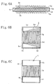
- a plate fin heat exchanger for a high temperature with the structure shown in FIGS. 4 to 6 was employed in a layout shown in FIGS. 9C, D as a regenerator for a micro gas turbine power generator.
- a gas turbine was disposed in the space 23 inside the inner tube 21, the exhaust gases released therefrom were caused to make a U turn, and heat exchange with the air was conducted in fin-plate heat exchangers 1 disposed radially between the cylindrical body 20 and inner tube 21.
- the temperature of combustion exhaust gases was set to two levels of 800oC and 900oC.
- a heat-exchange efficiency of 90% could be obtained in both cases.
- An austenitic stainless steel and a stainless steel containing 5 wt.% Al were used as the material for the heat exchanger at a temperature of exhaust gases of 800oC and 900oC, respectively.
- the plate fin heat exchanger for a high temperature in accordance with the present invention has a structure in which employing independent configurations for low-temperature channels makes it possible to lessen thermal stresses caused by non-uniform temperature distribution inside fluid channels and in the entire apparatus occurring when high-temperature combustion gas flows therein, to obtain high endurance and heat exchange efficiency under extreme variations of thermal load that are required for plate fin heat exchangers for regeneration in micro gas turbine generators, and to make a transition to a modular structure, to reduce the number of soldering operations, and to obtain excellent mass productivity.
- the structure of the heat exchanger in accordance with the present invention is made independent for each low-temperature fluid channel, a multifluid heat exchanger can be implemented in which steam can be obtained by introducing water instated of compressed air as in the above-described structure examples.
- independent configurations were employed for each low-temperature fluid channel and cantilever support was provided on the side surface of the container. Therefore, such a structure was beneficial in terms of maintenance because once a problem has risen associated with any of the low-temperature fluid channels, it could be easily closed or replaced.
- the advantage of the structures of Embodiment 2 and Embodiment 3 is that the assembly units containing a low-temperature fluid channel as the main component have a base shape of a rectangular plate and can be assembled merely by stacking, without any molding. Furthermore, assembling can be conducted by joining by means of soldering or welding only in a very few necessary places.
Landscapes
- Engineering & Computer Science (AREA)
- Physics & Mathematics (AREA)
- Thermal Sciences (AREA)
- Mechanical Engineering (AREA)
- General Engineering & Computer Science (AREA)
- Heat-Exchange Devices With Radiators And Conduit Assemblies (AREA)
Applications Claiming Priority (9)
| Application Number | Priority Date | Filing Date | Title |
|---|---|---|---|
| JP37090099 | 1999-12-27 | ||
| JP37090099A JP4473996B2 (ja) | 1999-12-27 | 1999-12-27 | 高温用プレートフィン型熱交換器 |
| JP2000167321 | 2000-06-05 | ||
| JP2000167321A JP2001349679A (ja) | 2000-06-05 | 2000-06-05 | 高温用プレートフィン型熱交換器 |
| JP2000242147A JP2002054887A (ja) | 2000-08-10 | 2000-08-10 | 高温用プレートフィン型熱交換器 |
| JP2000242147 | 2000-08-10 | ||
| JP2000282103A JP2002090078A (ja) | 2000-09-18 | 2000-09-18 | 高温用プレートフィン型熱交換器 |
| JP2000282103 | 2000-09-18 | ||
| PCT/JP2000/009209 WO2001048432A1 (fr) | 1999-12-27 | 2000-12-25 | Echangeur thermique haute temperature a ailette plate |
Publications (2)
| Publication Number | Publication Date |
|---|---|
| EP1243886A1 true EP1243886A1 (fr) | 2002-09-25 |
| EP1243886A4 EP1243886A4 (fr) | 2006-05-03 |
Family
ID=27480849
Family Applications (1)
| Application Number | Title | Priority Date | Filing Date |
|---|---|---|---|
| EP00985871A Withdrawn EP1243886A4 (fr) | 1999-12-27 | 2000-12-25 | Echangeur thermique haute temperature a ailette plate |
Country Status (4)
| Country | Link |
|---|---|
| US (2) | US6840313B2 (fr) |
| EP (1) | EP1243886A4 (fr) |
| AU (1) | AU2224501A (fr) |
| WO (1) | WO2001048432A1 (fr) |
Cited By (6)
| Publication number | Priority date | Publication date | Assignee | Title |
|---|---|---|---|---|
| DE10328746A1 (de) * | 2003-06-25 | 2005-01-13 | Behr Gmbh & Co. Kg | Vorrichtung zum mehrstufigen Wärmeaustausch und Verfahren zur Herstellung einer derartigen Vorrichtung |
| WO2006029761A1 (fr) * | 2004-09-13 | 2006-03-23 | Behr Gmbh & Co. Kg | Refroidisseur d'air de suralimentation, en particulier pour vehicules automobiles |
| CN104422311A (zh) * | 2013-08-29 | 2015-03-18 | 张鑫 | 纯逆流少接点管片一体高效风管换热器 |
| EP3106817A1 (fr) * | 2015-06-18 | 2016-12-21 | Hamilton Sundstrand Corporation | Échangeur thermique à ailettes-plaques |
| CN107202508A (zh) * | 2017-07-07 | 2017-09-26 | 中国科学院工程热物理研究所 | 换热单元及换热器 |
| US11268402B2 (en) | 2018-04-11 | 2022-03-08 | Raytheon Technologies Corporation | Blade outer air seal cooling fin |
Families Citing this family (42)
| Publication number | Priority date | Publication date | Assignee | Title |
|---|---|---|---|---|
| JP4676438B2 (ja) * | 2003-10-20 | 2011-04-27 | ベール ゲーエムベーハー ウント コー カーゲー | 熱交換器 |
| US7093649B2 (en) * | 2004-02-10 | 2006-08-22 | Peter Dawson | Flat heat exchanger plate and bulk material heat exchanger using the same |
| DE102004018197A1 (de) * | 2004-04-15 | 2005-11-03 | Modine Manufacturing Co., Racine | Abgaswärmetauscher |
| SE527727C2 (sv) * | 2004-08-18 | 2006-05-23 | Scania Cv Abp | Värmeväxlare |
| FR2887020B1 (fr) * | 2005-06-09 | 2007-08-31 | Air Liquide | Echangeur de chaleur a plaques avec structure d'echange formant plusieurs canaux dans un passage |
| US7272005B2 (en) * | 2005-11-30 | 2007-09-18 | International Business Machines Corporation | Multi-element heat exchange assemblies and methods of fabrication for a cooling system |
| US8136578B2 (en) * | 2006-03-13 | 2012-03-20 | Volvo Lastvagnar Ab | Heat exchanger for EGR-gas |
| ITMN20060020A1 (it) * | 2006-03-17 | 2007-09-18 | Daniele Bresti | Struttura di scambiatore di calore |
| DE102006026075A1 (de) * | 2006-06-03 | 2007-12-06 | Hydac System Gmbh | Wärmeaustauschvorrichtung |
| JP4781929B2 (ja) * | 2006-07-25 | 2011-09-28 | 富士通株式会社 | 電子機器 |
| JP2008027374A (ja) * | 2006-07-25 | 2008-02-07 | Fujitsu Ltd | 液冷ユニット用受熱器および液冷ユニット並びに電子機器 |
| JP5283836B2 (ja) | 2006-07-25 | 2013-09-04 | 富士通株式会社 | 液冷ユニット用受熱器および液冷ユニット並びに電子機器 |
| JP4842040B2 (ja) * | 2006-07-25 | 2011-12-21 | 富士通株式会社 | 電子機器 |
| JP5133531B2 (ja) * | 2006-07-25 | 2013-01-30 | 富士通株式会社 | 液冷ユニット用熱交換器および液冷ユニット並びに電子機器 |
| JP2008027370A (ja) * | 2006-07-25 | 2008-02-07 | Fujitsu Ltd | 電子機器 |
| JP5148079B2 (ja) * | 2006-07-25 | 2013-02-20 | 富士通株式会社 | 液冷ユニット用熱交換器および液冷ユニット並びに電子機器 |
| US8985198B2 (en) * | 2006-08-18 | 2015-03-24 | Modine Manufacturing Company | Stacked/bar plate charge air cooler including inlet and outlet tanks |
| JP4259583B2 (ja) * | 2007-02-15 | 2009-04-30 | 株式会社デンソー | 排気熱回収装置 |
| EP2137478A2 (fr) * | 2007-04-11 | 2009-12-30 | Behr GmbH & Co. KG | Échangeur de chaleur |
| JP5116082B2 (ja) * | 2007-04-17 | 2013-01-09 | 住友精密工業株式会社 | 高熱伝導複合材料 |
| TWM329810U (en) * | 2007-08-31 | 2008-04-01 | Yu-Nung Shen | Heat dissipation device |
| ES2481447T3 (es) * | 2008-01-10 | 2014-07-30 | Haldor Topsoe A/S | Método y sistema para la purificación del gas de escape de motores diesel |
| WO2011009080A2 (fr) * | 2009-07-17 | 2011-01-20 | Lockheed Martin Corporation | Echangeur de chaleur et procédé de fabrication de celui-ci |
| DE102009059032A1 (de) * | 2009-12-18 | 2011-06-22 | Dräger Medical GmbH, 23558 | Beatmungsvorrichtung |
| FR2958389B1 (fr) * | 2010-03-31 | 2012-07-13 | Valeo Systemes Thermiques | Echangeur de chaleur et lame pour l'echangeur |
| KR101266917B1 (ko) | 2011-12-13 | 2013-05-27 | 주식회사 코렌스 | 웨이브핀을 이용한 과열증기발생장치 |
| CN103841791A (zh) * | 2012-11-21 | 2014-06-04 | 华为技术有限公司 | 换热装置及机柜 |
| DE102012222638A1 (de) * | 2012-12-10 | 2014-06-12 | Behr Gmbh & Co. Kg | Wärmeübertrager |
| EP2962052B1 (fr) * | 2013-03-02 | 2020-02-12 | James Carl Loebig | Échangeur de chaleur à microcanaux et procédés de fabrication |
| KR101440723B1 (ko) * | 2013-03-14 | 2014-09-17 | 정인숙 | 현열교환기, 이를 포함하는 열회수 환기장치, 및 그 해빙운전과 점검운전 방법 |
| US9657999B2 (en) | 2014-11-11 | 2017-05-23 | Northrop Grumman Systems Corporation | Alternating channel heat exchanger |
| CN104713391B (zh) * | 2014-12-25 | 2017-02-22 | 马勒技术投资(中国)有限公司 | 一种可多回路换热的水冷式换热器 |
| US20160377350A1 (en) * | 2015-06-29 | 2016-12-29 | Honeywell International Inc. | Optimized plate fin heat exchanger for improved compliance to improve thermal life |
| CN106225523B (zh) * | 2016-07-22 | 2018-09-14 | 中国科学院理化技术研究所 | 一种交变流动换热器 |
| WO2018163692A1 (fr) * | 2017-03-07 | 2018-09-13 | 株式会社Ihi | Dissipateur de chaleur pour aéronef |
| NL2019792B1 (en) * | 2017-10-24 | 2019-04-29 | Micro Turbine Tech B V | Heat exchanger comprising a stack of cells and method of manufacturing such a heat exchanger |
| CN108180773A (zh) * | 2018-01-29 | 2018-06-19 | 西安热工研究院有限公司 | 一种间断翅片结构印刷电路板式换热器芯体 |
| CN109270495A (zh) * | 2018-11-06 | 2019-01-25 | 上海航天电子通讯设备研究所 | 一种雷达内外循环强迫风冷散热结构及雷达 |
| CN109297215A (zh) * | 2018-12-18 | 2019-02-01 | 湖北美标汽车制冷系统有限公司 | 一种用于怠速下空调制冷性能提升的回热器 |
| CN109813158A (zh) * | 2019-03-20 | 2019-05-28 | 杭州沈氏节能科技股份有限公司 | 板翅式换热器的板束加工方法 |
| CN110411239A (zh) * | 2019-07-18 | 2019-11-05 | 东南大学 | 仿生型换热器 |
| US20230194182A1 (en) * | 2021-12-17 | 2023-06-22 | Raytheon Technologies Corporation | Heat exchanger with partial-height folded fins |
Citations (6)
| Publication number | Priority date | Publication date | Assignee | Title |
|---|---|---|---|---|
| US2782009A (en) * | 1952-03-14 | 1957-02-19 | Gen Motors Corp | Heat exchangers |
| US3847211A (en) * | 1969-01-28 | 1974-11-12 | Sub Marine Syst Inc | Property interchange system for fluids |
| US4180973A (en) * | 1977-03-19 | 1980-01-01 | Kernforschungsanlage Julich Gesellschaft Mit Beschrankter Haftung | Vehicular gas turbine installation with ceramic recuperative heat exchanger elements arranged in rings around compressor, gas turbine and combustion chamber |
| US4442886A (en) * | 1982-04-19 | 1984-04-17 | North Atlantic Technologies, Inc. | Floating plate heat exchanger |
| JPS62233691A (ja) * | 1986-03-31 | 1987-10-14 | Sumitomo Precision Prod Co Ltd | 熱交換器 |
| JPH0614763U (ja) * | 1992-06-24 | 1994-02-25 | 石川島播磨重工業株式会社 | プレートフィン熱交換器 |
Family Cites Families (23)
| Publication number | Priority date | Publication date | Assignee | Title |
|---|---|---|---|---|
| US2462421A (en) * | 1944-10-26 | 1949-02-22 | Solar Aircraft Co | Crossflow heat exchanger |
| DE1601216B2 (de) * | 1967-11-03 | 1971-06-16 | Linde Ag, 6200 Wiesbaden | Blechtafel fuer platten waermetauscher mit einem stapel solcher blechtafeln |
| US3907032A (en) * | 1971-04-27 | 1975-09-23 | United Aircraft Prod | Tube and fin heat exchanger |
| US3825061A (en) * | 1971-05-13 | 1974-07-23 | United Aircraft Prod | Leak protected heat exchanger |
| US3759323A (en) * | 1971-11-18 | 1973-09-18 | Caterpillar Tractor Co | C-flow stacked plate heat exchanger |
| JPS57134698A (en) * | 1981-02-13 | 1982-08-19 | Toshiba Corp | Heat exchanging device |
| US4776387A (en) * | 1983-09-19 | 1988-10-11 | Gte Products Corporation | Heat recuperator with cross-flow ceramic core |
| US4596285A (en) * | 1985-03-28 | 1986-06-24 | North Atlantic Technologies, Inc. | Heat exchanger with resilient corner seals |
| US4623019A (en) * | 1985-09-30 | 1986-11-18 | United Aircraft Products, Inc. | Heat exchanger with heat transfer control |
| US4852640A (en) * | 1986-03-28 | 1989-08-01 | Exothermics-Eclipse Inc. | Recuperative heat exchanger |
| JPS63121287U (fr) * | 1987-01-26 | 1988-08-05 | ||
| JPH0645163Y2 (ja) * | 1988-12-23 | 1994-11-16 | 住友精密工業株式会社 | プレートフィン型熱交換器 |
| JPH02217789A (ja) * | 1989-02-15 | 1990-08-30 | Daikin Ind Ltd | 熱交換エレメント及び熱交換装置 |
| JPH0375497A (ja) * | 1989-08-18 | 1991-03-29 | Toyo Radiator Co Ltd | ダクト取付枠付積層型熱交換器の製造方法 |
| JPH063076A (ja) * | 1992-06-17 | 1994-01-11 | Toyo Radiator Co Ltd | 積層型熱交換器の製造方法 |
| JPH06238432A (ja) * | 1993-02-19 | 1994-08-30 | Toyo Radiator Co Ltd | 積層型熱交換器コアの製造方法 |
| FR2704310B1 (fr) * | 1993-04-20 | 1995-07-13 | Const Aero Navales | Echangeur a plaques et barrettes a circuits croises. |
| JP2824823B2 (ja) * | 1993-12-10 | 1998-11-18 | 東京電力株式会社 | プレートフィン型熱交換器の操業方法 |
| JPH11137968A (ja) * | 1997-11-14 | 1999-05-25 | Ishikawajima Harima Heavy Ind Co Ltd | 熱交換型脱硝装置 |
| US6059025A (en) * | 1998-03-05 | 2000-05-09 | Monsanto Enviro-Chem Systems, Inc. | Heat exchanger configuration |
| JP3100372B1 (ja) * | 1999-04-28 | 2000-10-16 | 春男 上原 | 熱交換器 |
| DE10034343C2 (de) * | 2000-07-14 | 2003-04-24 | Balcke Duerr Energietech Gmbh | Plattenwärmetauscher |
| US6516874B2 (en) * | 2001-06-29 | 2003-02-11 | Delaware Capital Formation, Inc. | All welded plate heat exchanger |
-
2000
- 2000-12-25 EP EP00985871A patent/EP1243886A4/fr not_active Withdrawn
- 2000-12-25 WO PCT/JP2000/009209 patent/WO2001048432A1/fr not_active Application Discontinuation
- 2000-12-25 US US10/168,939 patent/US6840313B2/en not_active Expired - Fee Related
- 2000-12-25 AU AU22245/01A patent/AU2224501A/en not_active Abandoned
-
2003
- 2003-12-29 US US10/747,418 patent/US6910528B2/en not_active Expired - Fee Related
Patent Citations (6)
| Publication number | Priority date | Publication date | Assignee | Title |
|---|---|---|---|---|
| US2782009A (en) * | 1952-03-14 | 1957-02-19 | Gen Motors Corp | Heat exchangers |
| US3847211A (en) * | 1969-01-28 | 1974-11-12 | Sub Marine Syst Inc | Property interchange system for fluids |
| US4180973A (en) * | 1977-03-19 | 1980-01-01 | Kernforschungsanlage Julich Gesellschaft Mit Beschrankter Haftung | Vehicular gas turbine installation with ceramic recuperative heat exchanger elements arranged in rings around compressor, gas turbine and combustion chamber |
| US4442886A (en) * | 1982-04-19 | 1984-04-17 | North Atlantic Technologies, Inc. | Floating plate heat exchanger |
| JPS62233691A (ja) * | 1986-03-31 | 1987-10-14 | Sumitomo Precision Prod Co Ltd | 熱交換器 |
| JPH0614763U (ja) * | 1992-06-24 | 1994-02-25 | 石川島播磨重工業株式会社 | プレートフィン熱交換器 |
Non-Patent Citations (2)
| Title |
|---|
| PATENT ABSTRACTS OF JAPAN vol. 012, no. 098 (M-680), 31 March 1988 (1988-03-31) & JP 62 233691 A (SUMITOMO PRECISION PROD CO LTD; others: 01), 14 October 1987 (1987-10-14) * |
| See also references of WO0148432A1 * |
Cited By (7)
| Publication number | Priority date | Publication date | Assignee | Title |
|---|---|---|---|---|
| DE10328746A1 (de) * | 2003-06-25 | 2005-01-13 | Behr Gmbh & Co. Kg | Vorrichtung zum mehrstufigen Wärmeaustausch und Verfahren zur Herstellung einer derartigen Vorrichtung |
| WO2006029761A1 (fr) * | 2004-09-13 | 2006-03-23 | Behr Gmbh & Co. Kg | Refroidisseur d'air de suralimentation, en particulier pour vehicules automobiles |
| CN104422311A (zh) * | 2013-08-29 | 2015-03-18 | 张鑫 | 纯逆流少接点管片一体高效风管换热器 |
| EP3106817A1 (fr) * | 2015-06-18 | 2016-12-21 | Hamilton Sundstrand Corporation | Échangeur thermique à ailettes-plaques |
| US10954858B2 (en) | 2015-06-18 | 2021-03-23 | Hamilton Sunstrand Corporation | Plate fin heat exchanger |
| CN107202508A (zh) * | 2017-07-07 | 2017-09-26 | 中国科学院工程热物理研究所 | 换热单元及换热器 |
| US11268402B2 (en) | 2018-04-11 | 2022-03-08 | Raytheon Technologies Corporation | Blade outer air seal cooling fin |
Also Published As
| Publication number | Publication date |
|---|---|
| US6910528B2 (en) | 2005-06-28 |
| EP1243886A4 (fr) | 2006-05-03 |
| US6840313B2 (en) | 2005-01-11 |
| AU2224501A (en) | 2001-07-09 |
| WO2001048432A1 (fr) | 2001-07-05 |
| US20030075308A1 (en) | 2003-04-24 |
| US20040149425A1 (en) | 2004-08-05 |
Similar Documents
| Publication | Publication Date | Title |
|---|---|---|
| US6840313B2 (en) | Plate fin type heat exchanger for high temperature | |
| US4073340A (en) | Formed plate type heat exchanger | |
| US8028410B2 (en) | Gas turbine regenerator apparatus and method of manufacture | |
| US5004044A (en) | Compact rectilinear heat exhanger | |
| US6390185B1 (en) | Annular flow concentric tube recuperator | |
| US4310960A (en) | Method of fabrication of a formed plate, counterflow fluid heat exchanger and apparatus thereof | |
| CA2571236A1 (fr) | Echangeur de chaleur avec tubes collecteurs | |
| US4134195A (en) | Method of manifold construction for formed tube-sheet heat exchanger and structure formed thereby | |
| KR102506094B1 (ko) | 단일 경로 직교류식 열교환기 | |
| US7861510B1 (en) | Ceramic regenerator for a gas turbine engine | |
| US20040003916A1 (en) | Unit cell U-plate-fin crossflow heat exchanger | |
| JP2002350092A (ja) | 熱交換器とこれを用いたガスタービン装置 | |
| JP7299902B2 (ja) | セルのスタックを有する熱交換器 | |
| JP2004037020A (ja) | 熱交換器及びそれを利用した熱交換式反応器 | |
| WO2003056265A1 (fr) | Echangeur thermique | |
| JP4473996B2 (ja) | 高温用プレートフィン型熱交換器 | |
| US3814171A (en) | Stationary heat exchanger | |
| US11879691B2 (en) | Counter-flow heat exchanger | |
| JP2004516423A (ja) | タービンの復熱装置 | |
| WO1991002146A1 (fr) | Echangeur de chaleur circonferentiel | |
| JP2002071288A (ja) | プレートフィン型熱交換器 | |
| RU2819324C1 (ru) | Пластинчатый теплообменник со спиралевидными турбулизаторами для газотурбинной установки | |
| JP2002054887A (ja) | 高温用プレートフィン型熱交換器 | |
| RU2819325C1 (ru) | Пластинчатый теплообменник с коллектором для разделения горячего и холодного теплоносителя | |
| RU2790537C1 (ru) | Теплообменное устройство |
Legal Events
| Date | Code | Title | Description |
|---|---|---|---|
| PUAI | Public reference made under article 153(3) epc to a published international application that has entered the european phase |
Free format text: ORIGINAL CODE: 0009012 |
|
| 17P | Request for examination filed |
Effective date: 20020718 |
|
| AK | Designated contracting states |
Kind code of ref document: A1 Designated state(s): AT BE CH CY DE DK ES FI FR GB GR IE IT LI LU MC NL PT SE TR |
|
| RBV | Designated contracting states (corrected) |
Designated state(s): GB |
|
| REG | Reference to a national code |
Ref country code: DE Ref legal event code: 8566 |
|
| A4 | Supplementary search report drawn up and despatched |
Effective date: 20060322 |
|
| STAA | Information on the status of an ep patent application or granted ep patent |
Free format text: STATUS: THE APPLICATION IS DEEMED TO BE WITHDRAWN |
|
| 18D | Application deemed to be withdrawn |
Effective date: 20060629 |