EP1243387A2 - Formrahmen für eine Form - Google Patents
Formrahmen für eine Form Download PDFInfo
- Publication number
- EP1243387A2 EP1243387A2 EP02000440A EP02000440A EP1243387A2 EP 1243387 A2 EP1243387 A2 EP 1243387A2 EP 02000440 A EP02000440 A EP 02000440A EP 02000440 A EP02000440 A EP 02000440A EP 1243387 A2 EP1243387 A2 EP 1243387A2
- Authority
- EP
- European Patent Office
- Prior art keywords
- frame
- mold
- cross
- longitudinal
- mold insert
- Prior art date
- Legal status (The legal status is an assumption and is not a legal conclusion. Google has not performed a legal analysis and makes no representation as to the accuracy of the status listed.)
- Granted
Links
Images

Classifications
-
- B—PERFORMING OPERATIONS; TRANSPORTING
- B28—WORKING CEMENT, CLAY, OR STONE
- B28B—SHAPING CLAY OR OTHER CERAMIC COMPOSITIONS; SHAPING SLAG; SHAPING MIXTURES CONTAINING CEMENTITIOUS MATERIAL, e.g. PLASTER
- B28B1/00—Producing shaped prefabricated articles from the material
- B28B1/08—Producing shaped prefabricated articles from the material by vibrating or jolting
- B28B1/081—Vibration-absorbing means
-
- B—PERFORMING OPERATIONS; TRANSPORTING
- B28—WORKING CEMENT, CLAY, OR STONE
- B28B—SHAPING CLAY OR OTHER CERAMIC COMPOSITIONS; SHAPING SLAG; SHAPING MIXTURES CONTAINING CEMENTITIOUS MATERIAL, e.g. PLASTER
- B28B7/00—Moulds; Cores; Mandrels
- B28B7/0002—Auxiliary parts or elements of the mould
- B28B7/0014—Fastening means for mould parts, e.g. for attaching mould walls on mould tables; Mould clamps
-
- B—PERFORMING OPERATIONS; TRANSPORTING
- B28—WORKING CEMENT, CLAY, OR STONE
- B28B—SHAPING CLAY OR OTHER CERAMIC COMPOSITIONS; SHAPING SLAG; SHAPING MIXTURES CONTAINING CEMENTITIOUS MATERIAL, e.g. PLASTER
- B28B7/00—Moulds; Cores; Mandrels
- B28B7/0029—Moulds or moulding surfaces not covered by B28B7/0058 - B28B7/36 and B28B7/40 - B28B7/465, e.g. moulds assembled from several parts
Definitions
- the invention relates to a mold frame for a mold for production of concrete moldings, in particular concrete blocks, consisting from longitudinal and transverse frame parts that are connected to each other and surround a mold insert containing several mold cavities.
- a molding frame which consists of consists of two longitudinal frame parts and two transverse frame parts are welded together at the four corners of the mold frame.
- the outer sides of the cross frame part have a flange, provided for connection to a lifting frame of the molding machine is.
- the inside of the mold frame are as sloping surfaces trained, which serve to accommodate the mold insert.
- the Outside of the mold insert consist of triangular Prisms that when inserting the mold insert into the welded Place the mold frame on the sloping surfaces of the mold frame.
- To hold the mold insert in the mold frame are from screwed to the bottom of the form frame pressure bars, which with a sloping surface at the bottom of the triangular prisms of the Form insert. Between the sloping surfaces of the mold frame and the mold insert are elastic damping plates inserted.
- the invention has for its object a form frame to create the type mentioned above, the high demands the jogger has grown and is quick and easy The mold insert can be changed.
- the object is achieved in that in each case a longitudinal frame part and a transverse frame part at the four corners the form frame positively and releasably connected to each other are.
- a positive and non-rotatable screw connection of the frame parts achieved in that each cross frame part on its two Front sides has a cross-section polygonal pin, which in a corresponding one, at the two ends of each longitudinal frame part recess recessed into the inside, polygonal in cross section engages releasably and non-rotatably, or vice versa, and both frame parts releasably connected to each other by a clamping screw are.
- the pins of the Cross frame parts and the depressions of the longitudinal frame parts each a common, horizontally and centrally arranged through hole for the clamping screw on the in a threaded hole of the cross frame part engages. Due to the relatively long length the tension screw increases the elastic compliance and hence the durability of the frame connection.
- the threaded hole is arranged in a screw nut, which can be inserted loosely into a recess in the cross frame part is.
- the threaded bore is advantageously in a cylindrical Screw nut arranged transversely to the cylinder axis, whereby the nut in a vertical hole in the cross frame part is stored. Because the nut is in the hole can turn, loads on the clamping screw a superimposed bending stress, the z. B. due to an oblique Support of the nut is avoided.
- the mold insert is held in the mold frame by that the connection between the mold frame and mold insert is a Tongue and groove connection is available on all four sides or only two opposite sides of the mold insert and the mold frame is provided.
- the mold insert is on the molding machine stretched on the vibrating table so that the forces caused by the Shake on the mold insert through the tongue and groove connection cushioned and tension-reducing from mold insert to Form frame and thus via the flange strip to the molding machine be directed.
- the groove and Spring connection between the mold frame and mold insert one worked into the inside of the cross and / or longitudinal frame parts, in cross-section triangular groove, one in cross-section also triangular on the outside of the mold frame molded spring engages.
- the transfer of forces and the effect of vibrations on vibrations the molding machine are additionally reduced if between the Groove of the mold frame and the tongue of the mold insert or vice versa Damping elements are arranged.
- the Damping elements on the contact surfaces of the spring of the mold insert be glued on or embedded in them.
- connection between the frame parts of the mold frame is highly resilient and durable. That by the vibrating forces and the pressing of the mold insert on the vibrating table Torques within the screw connection between the frame parts are formed by the polygonal pegs and recesses, that prevent the frame parts from twisting, fully absorbed.
- the molded frame screwed in this way has the stability of a welded frame, but with the advantage of a simple assembly, which is precise via the polygons Positioning allows.
- the exchange of the mold insert during a repair is due to the quick-release screw connection and the non-destructive loosening of the connection between The mold frame and mold insert can also be carried out easily by the customer.
- damping elements inside the tongue and groove connection between the mold frame and mold insert the efficiency of the vibration increases considerably, because the vibrating energy largely remains in the mold insert.
- the compression and the strength of the finished concrete blocks increases thereby by up to 25%.
- the mold frame 1 of a shape, not shown, for machine Production of concrete blocks consists of two parallel ones Longitudinal frame parts 2 and two parallel cross frame parts 3, the are screwed together at the four corners of the mold frame.
- a mold insert 5 clamped with several mold nests 6.
- each cross frame part 3 On the two end faces of each cross frame part 3 is in the extension the longitudinal axis of the cross frame part 3 each a polygon Shaped pin 7 with a square cross section.
- One of the pins 7 corresponding, square recess 8 is in the inside milled at the ends of each longitudinal frame part 2.
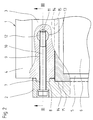
- a through hole 9 for a clamping screw 10 In the middle of Pin 7 and in the recess 8 is parallel to the longitudinal axis of the Cross frame part 3 a through hole 9 for a clamping screw 10 provided.
- the free end of the clamping screw 10 will after joining the two frame parts 2, 3 into a threaded hole 11 screwed a nut 12.
- the nut 12 is cylindrical and in a vertical shape Through hole 9 at right angles intersecting bore 13 in Cross frame part 3 inserted loosely and rotatably mounted.
- the Screw nut 12 is aligned in the bore 13 so that the Clamping screw 10 in the threaded bore running transversely to the cylinder axis 11 can intervene
- the pin 7 on the longitudinal frame parts 2 and the depressions 8 can be arranged on the transverse frame parts 3.
- Cross frame part 2, 3 has a continuous groove 14 for one Corresponding spring 15, which is continuously on the four outer sides of the mold insert 5 is arranged and engages in the groove 14.
- Corresponding spring 15 which is continuously on the four outer sides of the mold insert 5 is arranged and engages in the groove 14.
- the tongue and groove connection 14 formed in this way, 15 between mold frame 1 and mold insert 5 is on all four sides of the mold frame and the mold insert. It is a version is also possible in which the tongue and groove connection 14, 15 only on two opposite longitudinal or transverse frame parts 2, 3 is arranged.
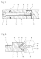
- Fig. 4 shows another embodiment of the tongue and groove connection between mold frame 1 and mold insert 5.
- a continuous, triangular Groove 16 incorporated, also triangular continuous spring 17 which engages on the outside on the transverse sides the mold insert 5 is located.
- the tongue and groove connection 16, 17 can also on all four sides of the mold frame 1 and the mold insert 5 be arranged.
- elastic damping plates 18 arranged in Recesses 19 of the contact surfaces 20 of the spring 17 are inserted.
- the damping plates 18 can also on the contact surfaces 20 of the Spring 17 are stuck on.
- the grooves 14; 16 on the outside of the mold insert 5 and the springs 15; 17 on the inside of the mold frame 1 be arranged.
Landscapes
- Engineering & Computer Science (AREA)
- Manufacturing & Machinery (AREA)
- Chemical & Material Sciences (AREA)
- Ceramic Engineering (AREA)
- Mechanical Engineering (AREA)
- Moulds, Cores, Or Mandrels (AREA)
- Moulds For Moulding Plastics Or The Like (AREA)
- Molds, Cores, And Manufacturing Methods Thereof (AREA)
- Mutual Connection Of Rods And Tubes (AREA)
- Eyeglasses (AREA)
- Golf Clubs (AREA)
- Shaping Of Tube Ends By Bending Or Straightening (AREA)
- Bending Of Plates, Rods, And Pipes (AREA)
Abstract
Description
- Fig. 1
- eine perspektivische Montagezeichnung eines Formrahmens und eines Formeinsatzes einer nicht näher dargestellten Form, im demontierten Zustand,
- Fig. 2
- eine Teildraufsicht auf die Verbindung zwischen den Rahmenteilen des Formrahmens, teilweise geschnitten,
- Fig. 3
- einen Schnitt gemäss der Linie III - III in Fig. 2 und
- Fig. 4
- einen Schnitt durch eine andere Ausführung der Nut- und Feder-Verbindung mit Dämpfungselementen zwischen Formrahmen und Formeinsatz.
Claims (9)
- Formrahmen für eine Form zur Herstellung von Betonformkörpern, insbesondere Betonformsteine, bestehend aus Längs- und Quer-Rahmenteilen, die miteinander verbunden sind und einen mehrere Formnester enthaltenden Formeinsatz umgeben, dadurch gekennzeichnet, dass jeweils ein Längs-Rahmenteil (2) und ein Quer-Rahmenteil (3) an den vier Ecken des Formrahmens (1) formschlüssig und lösbar miteinander verbunden sind.
- Formrahmen nach Anspruch 1, dadurch gekennzeichnet, dass jedes Quer-Rahmenteil (3) an seinen beiden Stinseiten je einen horizontalen, im Querschnitt polygonen Zapfen (7) aufweist, der in eine entsprechende, an den beiden Enden jedes Längs-Rahmenteiles (2) in die Innenseite eingearbeitete, im Querschnitt polygone Vertiefung (8) lösbar und unverdrehbar eingreift, oder umgekehrt, und beide Rahmenteile (2, 3) durch eine Spannschraube (10) lösbar miteinander verbunden sind.
- Formrahmen nach Anspruch 1 oder 2, dadurch gekennzeichnet, dass die Zapfen (7) der Quer-Rahmenteile (3) und die Vertiefungen (8) der Längs-Rahmenteile (2) jeweils eine gemeinsame, horizontal und mittig angeordnete Durchgangsbohrung (9) für die Spannschraube (10) aufweisen, die in eine Gewindebohrung (11) des Quer-Rahmenteiles (3) eingreift.
- Formrahmen nach Anspruch 3, dadurch gekennzeichnet, dass die Gewindebohrung (11) in einer Schraubenmutter (12) angeordnet ist, die in eine Aussparung des Quer-Rahmenteils (3) lose einsetzbar ist.
- Formrahmen nach Anspruch 3 oder 4, dadurch gekennzeichnet, dass die Gewindebohrung (11) in einer zylindrischen Schraubenmutter (12) quer zur Zylinderachse verlaufend angeordnet ist und die Schraubenmutter (12) in einer vertikalen Bohrung (13) des Quer-Rahmenteils (3) gelagert ist.
- Formrahmen nach einem der Ansprüche 1 bis 5, dadurch gekennzeichnet, dass die Verbindung zwischen Formrahmen (1) und Formeinsatz (5) eine Nut- und Feder-Verbindung (14, 15; 16, 17) ist, die an allen vier Seiten oder nur an zwei gegenüberliegenden Seiten des Formeinsatzes (5) und des Formrahmens (1) vorgesehen ist.
- Formrahmen nach einem der Ansprüche 1 bis 6, dadurch gekennzeichnet, dass die Nut- und Feder-Verbindung zwischen Formrahmen (1) und Formeinsatzt (5) aus einer in die Innenseite der Querund/oder Längs-Rahmenteile (3, 2) eingearbeitete, im Querschnitt dreieckförmigen Nut (16) besteht, in die eine im Querschnitt ebenfalls dreieckförmige, an den Aussenseiten des Formeinsatzes (1) angeformte Feder (17) eingreift.
- Formrahmen nach einem der Ansprüche 1 bis 7, dadurch gekennzeichnet, dass zwischen der Nut (14; 16) des Formrahmens (1) und der Feder (15; 17) des Formeinsatzes (5), oder umgekehrt, Dämpfungsplatten (18) angeordnet sind.
- Formrahmen nach Anspruch 8, dadurch gekennzeichnet, dass die Dämpfungsplatten (18) auf die Kontaktflächen (20) der Feder (17) aufgeklebt oder in diese eingelassen sind.
Priority Applications (2)
| Application Number | Priority Date | Filing Date | Title |
|---|---|---|---|
| DE20211027U DE20211027U1 (de) | 2002-01-08 | 2002-01-08 | Formrahmen für eine Form |
| DK02000440T DK1243387T3 (da) | 2001-03-23 | 2002-01-08 | Formramme til en form |
Applications Claiming Priority (2)
| Application Number | Priority Date | Filing Date | Title |
|---|---|---|---|
| DE10114398 | 2001-03-23 | ||
| DE10114398A DE10114398A1 (de) | 2001-03-23 | 2001-03-23 | Formrahmen für eine Form |
Publications (3)
| Publication Number | Publication Date |
|---|---|
| EP1243387A2 true EP1243387A2 (de) | 2002-09-25 |
| EP1243387A3 EP1243387A3 (de) | 2003-10-29 |
| EP1243387B1 EP1243387B1 (de) | 2005-08-10 |
Family
ID=7678794
Family Applications (1)
| Application Number | Title | Priority Date | Filing Date |
|---|---|---|---|
| EP02000440A Expired - Lifetime EP1243387B1 (de) | 2001-03-23 | 2002-01-08 | Formrahmen für eine Form |
Country Status (11)
| Country | Link |
|---|---|
| US (2) | US20020134906A1 (de) |
| EP (1) | EP1243387B1 (de) |
| CN (1) | CN1250381C (de) |
| AT (1) | ATE301537T1 (de) |
| CA (1) | CA2350370C (de) |
| CZ (1) | CZ303441B6 (de) |
| DE (2) | DE10114398A1 (de) |
| DK (1) | DK1243387T3 (de) |
| ES (1) | ES2247205T3 (de) |
| HK (1) | HK1047723B (de) |
| PL (1) | PL198077B1 (de) |
Families Citing this family (23)
| Publication number | Priority date | Publication date | Assignee | Title |
|---|---|---|---|---|
| CA2431359A1 (en) * | 2001-03-29 | 2002-10-10 | Rampf Formen Gmbh | Mold for the production of concrete articles |
| WO2003092973A1 (de) * | 2002-05-03 | 2003-11-13 | Rampf Formen Gmbh | Form zur herstellung von formteilen auf einem rütteltisch |
| DE10254322A1 (de) * | 2002-11-21 | 2004-06-03 | Kobra Formen Gmbh | Anordnung zur Herstellung von Betonformsteinen |
| DE20219768U1 (de) * | 2002-12-20 | 2003-03-06 | KOBRA Formen GmbH, 08485 Lengenfeld | Vorrichtung zur Herstellung von Betonformsteinen |
| DK176725B1 (da) * | 2003-07-04 | 2009-05-04 | Kvm Industrimaskiner As | Fremgangsmåde til fremstilling af et vibrationsbord til betonstöbemaskiner samt et vibrationsbrod fremstillet ifölge fremgangsmåden |
| DE102005017670A1 (de) * | 2005-04-16 | 2006-10-19 | Kobra Formen Gmbh | Vorrichtung zur Herstellung von Betonformsteinen und Formensystem zur Verwendung in einer solchen Vorrichtung |
| US20070262229A1 (en) * | 2006-05-09 | 2007-11-15 | Columbia Machine, Inc. | Concrete mold box assembly with polyurethane bonded compartments |
| DE102009048599A1 (de) * | 2009-10-07 | 2011-04-14 | Rampf Formen Gmbh | Form zur Herstellung von Formkörpern und Verfahren zur Herstellung einer Form für die Herstellung von Formkörpern |
| DE202009013663U1 (de) * | 2009-10-30 | 2011-03-17 | Paul Hettich Gmbh & Co. Kg | Auszugsführung und Haushaltsgerät |
| CN102686768B (zh) * | 2009-12-11 | 2016-02-03 | Kgt石墨科技有限公司 | 衬底支承体 |
| CN102689355A (zh) * | 2012-06-26 | 2012-09-26 | 蓝福模具(太仓)有限公司 | 拼装式砌块成型模芯 |
| ITMI20132011A1 (it) | 2013-12-02 | 2015-06-03 | Vh S R L | Stampo per prodotti di rivestimento per l'edilizia e impianto per la fabbricazione di tali prodotti di rivestimento |
| CN105058560B (zh) * | 2015-08-18 | 2017-09-01 | 太仓富莱克斯模具科技有限公司 | 一种螺栓快装制砖模具 |
| CN105058559A (zh) * | 2015-09-15 | 2015-11-18 | 李春福 | 剪刀格构式空心砌块模具 |
| CN105881718B (zh) * | 2016-06-03 | 2018-05-01 | 太仓富莱克斯模具科技有限公司 | 一种制砖模具的模芯组件及模框组件 |
| CN106596238B (zh) * | 2016-10-19 | 2023-07-21 | 浙江科技学院(浙江中德科技促进中心) | 吻合岩石结构面上下盘的整体成型制作模具 |
| CN108621287B (zh) * | 2018-07-12 | 2023-07-28 | 太仓富莱克斯模具科技有限公司 | 一种减震增稳制砖模具 |
| CN109483696B (zh) * | 2018-12-07 | 2020-12-15 | 湖南五新模板有限公司 | 一种具有保护机构的高效混凝土预制块模具 |
| CN112192722B (zh) * | 2019-07-08 | 2025-02-11 | 河南众鼎智拓环保科技有限公司 | 一种建筑用混凝土砌块生产模具 |
| CN115890879A (zh) * | 2022-11-25 | 2023-04-04 | 苏州良浦住宅工业有限公司 | 一种可调式组合窗模模具 |
| US12467212B1 (en) | 2024-01-16 | 2025-11-11 | Rich Smith | Ground-leveling form |
| CN118422866B (zh) * | 2024-07-05 | 2024-09-24 | 山西八建集团有限公司 | 一种混凝土浇筑模板及混凝土浇筑方法 |
| MA67279A1 (fr) * | 2024-08-26 | 2026-02-27 | Kobra Formen Morocco | Système de montage de moules en acier pour blocs de construction par tenons et mortaises |
Family Cites Families (12)
| Publication number | Priority date | Publication date | Assignee | Title |
|---|---|---|---|---|
| US895614A (en) * | 1907-12-23 | 1908-08-11 | Emil Buscher | Block-molding machine. |
| US3932098A (en) * | 1974-12-18 | 1976-01-13 | Spartek Inc. | Case assembly with tungsten carbide inserts for ceramic tile die |
| DE2710643A1 (de) * | 1977-03-11 | 1978-09-14 | Hermann Seiler | Einrichtung zur befestigung von formen |
| DE3312544A1 (de) * | 1983-04-07 | 1984-12-13 | Hess Maschinenfabrik GmbH & Co KG, 5909 Burbach | Mittel zur laemminderung an betonsteinformmaschinen |
| DE3710186C1 (en) * | 1987-03-27 | 1988-06-16 | Hmb Maschb Gmbh | Concrete-block mould |
| DE4242686C2 (de) * | 1992-12-17 | 2001-02-15 | Rampf Formen Gmbh | Form zur Herstellung von Betonkörpern |
| US5372349A (en) * | 1993-04-27 | 1994-12-13 | Jte, Inc. | Single form system and method for molding pre-cast structural wall panels of different sizes for different types of wall systems |
| US5728312A (en) * | 1994-05-20 | 1998-03-17 | Waffle-Crete International, Inc. | Mold for forming precast conctete panels |
| DE4422442A1 (de) * | 1994-06-29 | 1996-01-11 | Reymann & Schwoerer Gmbh & Co | Hilfsvorrichtung zum Herstellen von Schalungsteilen |
| US5743510A (en) * | 1994-12-21 | 1998-04-28 | Columbia Machine | Self-aligning mold box assembly |
| DE19508152A1 (de) * | 1995-03-08 | 1996-09-12 | Kobra Formen & Anlagenbau Gmbh | Rüttelform |
| US6007321A (en) * | 1997-09-04 | 1999-12-28 | Meckel; Kevin | Unitary paver mold |
-
2001
- 2001-03-23 DE DE10114398A patent/DE10114398A1/de not_active Withdrawn
- 2001-06-12 CA CA002350370A patent/CA2350370C/en not_active Expired - Lifetime
- 2001-08-22 US US09/933,669 patent/US20020134906A1/en not_active Abandoned
-
2002
- 2002-01-08 DE DE50203851T patent/DE50203851D1/de not_active Expired - Lifetime
- 2002-01-08 DK DK02000440T patent/DK1243387T3/da active
- 2002-01-08 AT AT02000440T patent/ATE301537T1/de active
- 2002-01-08 ES ES02000440T patent/ES2247205T3/es not_active Expired - Lifetime
- 2002-01-08 EP EP02000440A patent/EP1243387B1/de not_active Expired - Lifetime
- 2002-01-18 CZ CZ20020214A patent/CZ303441B6/cs not_active IP Right Cessation
- 2002-01-31 CN CNB021031231A patent/CN1250381C/zh not_active Expired - Lifetime
- 2002-03-05 PL PL352628A patent/PL198077B1/pl unknown
- 2002-12-23 HK HK02109280.8A patent/HK1047723B/zh not_active IP Right Cessation
-
2003
- 2003-09-04 US US10/654,083 patent/US7004442B2/en not_active Expired - Lifetime
Also Published As
| Publication number | Publication date |
|---|---|
| EP1243387A3 (de) | 2003-10-29 |
| US7004442B2 (en) | 2006-02-28 |
| US20020134906A1 (en) | 2002-09-26 |
| CZ2002214A3 (cs) | 2003-01-15 |
| CA2350370C (en) | 2008-11-18 |
| PL352628A1 (en) | 2002-10-07 |
| CN1250381C (zh) | 2006-04-12 |
| ES2247205T3 (es) | 2006-03-01 |
| EP1243387B1 (de) | 2005-08-10 |
| PL198077B1 (pl) | 2008-05-30 |
| HK1047723B (zh) | 2006-10-13 |
| ATE301537T1 (de) | 2005-08-15 |
| HK1047723A1 (en) | 2003-03-07 |
| CA2350370A1 (en) | 2002-09-23 |
| CN1376562A (zh) | 2002-10-30 |
| DE50203851D1 (de) | 2005-09-15 |
| DE10114398A1 (de) | 2002-09-26 |
| DK1243387T3 (da) | 2005-09-26 |
| US20040056171A1 (en) | 2004-03-25 |
| CZ303441B6 (cs) | 2012-09-12 |
Similar Documents
| Publication | Publication Date | Title |
|---|---|---|
| EP1243387A2 (de) | Formrahmen für eine Form | |
| DE60109668T2 (de) | Verbindungselement eines Traggerüsts | |
| DE2847006B1 (de) | AEussere Spannvorrichtung fuer chirurgische Zwecke | |
| DE202020100903U1 (de) | Montierter Stuhl | |
| DE60100102T2 (de) | Vorrichtung zur Verbindung von winklig aneinanderstossenden Rahmenteilen zur Herstellung von rechteckigen Rahmen | |
| DE3014507C2 (de) | ||
| DE2749184A1 (de) | Baukastensystem zum aufbauen von maschinenkoerpern o.dgl. | |
| DE10315095A1 (de) | Befestigungseinrichtung für einen Wärmeübertrager und Wärmeübertragungsbefestigung | |
| DE20211027U1 (de) | Formrahmen für eine Form | |
| CH686848A5 (de) | Verbindung fuer Hausschornsteinelemente. | |
| DE202011003613U1 (de) | Zusammensetzbarer Leichtbauprofilträger | |
| EP1388626B1 (de) | Halter | |
| DE8624567U1 (de) | Verbindungselement für Profilstreben | |
| DD210324A1 (de) | Rahmen aus stabartigen elementarteilen, hauptsaechlich fuer fensterrahmen und fensterfluegel | |
| DE102009011707A1 (de) | Modulares Regalsystem | |
| DE102005023235B3 (de) | Kolben-Zylinder-Aggregat | |
| DE102004060419B3 (de) | Herzstück für Weichen | |
| DE10347882B3 (de) | Bettgestell | |
| DE319911C (de) | Geruest fuer Schaukaesten, Ladenfronten u. dgl. aus durch Verbindungsstuecke zusammengehaltenen Rahmenstangen | |
| DE102011106998A1 (de) | Montagevorrichtung sowie Maschinenanordnung mit einer solchen Montagevorrichtung | |
| DE102010023609A1 (de) | Aufsatzbacke für einen Schraubstock | |
| DE69709466T2 (de) | Zylinderkopf einer Brennkraftmaschine mit einer Vorrichtung zum Spannen einer Treibkette zum Verbinden von zwei Nockenwellen | |
| DE4337859A1 (de) | Modulbauelemente für Konstruktionen zum Tragen und Halten von Werkstücken | |
| EP1617088A1 (de) | Trageinrichtung | |
| DE202016100024U1 (de) | Unterkasten für ein Boxspringbett |
Legal Events
| Date | Code | Title | Description |
|---|---|---|---|
| PUAI | Public reference made under article 153(3) epc to a published international application that has entered the european phase |
Free format text: ORIGINAL CODE: 0009012 |
|
| AK | Designated contracting states |
Kind code of ref document: A2 Designated state(s): AT BE CH CY DE DK ES FI FR GB GR IE IT LI LU MC NL PT SE TR |
|
| AX | Request for extension of the european patent |
Free format text: AL;LT;LV;MK;RO;SI |
|
| RAP1 | Party data changed (applicant data changed or rights of an application transferred) |
Owner name: KOBRA FORMEN GMBH |
|
| PUAL | Search report despatched |
Free format text: ORIGINAL CODE: 0009013 |
|
| AK | Designated contracting states |
Kind code of ref document: A3 Designated state(s): AT BE CH CY DE DK ES FI FR GB GR IE IT LI LU MC NL PT SE TR |
|
| AX | Request for extension of the european patent |
Extension state: AL LT LV MK RO SI |
|
| 17P | Request for examination filed |
Effective date: 20040429 |
|
| AKX | Designation fees paid |
Designated state(s): AT BE CH CY DE DK ES FI FR GB GR IE IT LI LU MC NL PT SE TR |
|
| 17Q | First examination report despatched |
Effective date: 20040702 |
|
| GRAP | Despatch of communication of intention to grant a patent |
Free format text: ORIGINAL CODE: EPIDOSNIGR1 |
|
| GRAS | Grant fee paid |
Free format text: ORIGINAL CODE: EPIDOSNIGR3 |
|
| GRAA | (expected) grant |
Free format text: ORIGINAL CODE: 0009210 |
|
| AK | Designated contracting states |
Kind code of ref document: B1 Designated state(s): AT BE CH CY DE DK ES FI FR GB GR IE IT LI LU MC NL PT SE TR |
|
| PG25 | Lapsed in a contracting state [announced via postgrant information from national office to epo] |
Ref country code: TR Free format text: LAPSE BECAUSE OF FAILURE TO SUBMIT A TRANSLATION OF THE DESCRIPTION OR TO PAY THE FEE WITHIN THE PRESCRIBED TIME-LIMIT Effective date: 20050810 Ref country code: IT Free format text: LAPSE BECAUSE OF FAILURE TO SUBMIT A TRANSLATION OF THE DESCRIPTION OR TO PAY THE FEE WITHIN THE PRESCRIBED TIME-LIMIT;WARNING: LAPSES OF ITALIAN PATENTS WITH EFFECTIVE DATE BEFORE 2007 MAY HAVE OCCURRED AT ANY TIME BEFORE 2007. THE CORRECT EFFECTIVE DATE MAY BE DIFFERENT FROM THE ONE RECORDED. Effective date: 20050810 Ref country code: FI Free format text: LAPSE BECAUSE OF FAILURE TO SUBMIT A TRANSLATION OF THE DESCRIPTION OR TO PAY THE FEE WITHIN THE PRESCRIBED TIME-LIMIT Effective date: 20050810 Ref country code: IE Free format text: LAPSE BECAUSE OF FAILURE TO SUBMIT A TRANSLATION OF THE DESCRIPTION OR TO PAY THE FEE WITHIN THE PRESCRIBED TIME-LIMIT Effective date: 20050810 |
|
| REG | Reference to a national code |
Ref country code: GB Ref legal event code: FG4D Free format text: NOT ENGLISH |
|
| REG | Reference to a national code |
Ref country code: CH Ref legal event code: EP |
|
| REG | Reference to a national code |
Ref country code: IE Ref legal event code: FG4D Free format text: LANGUAGE OF EP DOCUMENT: GERMAN |
|
| RAP2 | Party data changed (patent owner data changed or rights of a patent transferred) |
Owner name: KOBRA FORMEN GMBH |
|
| REF | Corresponds to: |
Ref document number: 50203851 Country of ref document: DE Date of ref document: 20050915 Kind code of ref document: P |
|
| REG | Reference to a national code |
Ref country code: DK Ref legal event code: T3 |
|
| GBT | Gb: translation of ep patent filed (gb section 77(6)(a)/1977) |
Effective date: 20050917 |
|
| REG | Reference to a national code |
Ref country code: SE Ref legal event code: TRGR |
|
| NLT2 | Nl: modifications (of names), taken from the european patent patent bulletin |
Owner name: KOBRA FORMEN GMBH Effective date: 20050914 |
|
| PG25 | Lapsed in a contracting state [announced via postgrant information from national office to epo] |
Ref country code: GR Free format text: LAPSE BECAUSE OF FAILURE TO SUBMIT A TRANSLATION OF THE DESCRIPTION OR TO PAY THE FEE WITHIN THE PRESCRIBED TIME-LIMIT Effective date: 20051110 |
|
| PG25 | Lapsed in a contracting state [announced via postgrant information from national office to epo] |
Ref country code: PT Free format text: LAPSE BECAUSE OF FAILURE TO SUBMIT A TRANSLATION OF THE DESCRIPTION OR TO PAY THE FEE WITHIN THE PRESCRIBED TIME-LIMIT Effective date: 20060110 |
|
| PG25 | Lapsed in a contracting state [announced via postgrant information from national office to epo] |
Ref country code: LU Free format text: LAPSE BECAUSE OF NON-PAYMENT OF DUE FEES Effective date: 20060131 Ref country code: LI Free format text: LAPSE BECAUSE OF NON-PAYMENT OF DUE FEES Effective date: 20060131 Ref country code: CH Free format text: LAPSE BECAUSE OF NON-PAYMENT OF DUE FEES Effective date: 20060131 Ref country code: MC Free format text: LAPSE BECAUSE OF NON-PAYMENT OF DUE FEES Effective date: 20060131 |
|
| REG | Reference to a national code |
Ref country code: ES Ref legal event code: FG2A Ref document number: 2247205 Country of ref document: ES Kind code of ref document: T3 |
|
| REG | Reference to a national code |
Ref country code: IE Ref legal event code: FD4D |
|
| PLBE | No opposition filed within time limit |
Free format text: ORIGINAL CODE: 0009261 |
|
| STAA | Information on the status of an ep patent application or granted ep patent |
Free format text: STATUS: NO OPPOSITION FILED WITHIN TIME LIMIT |
|
| 26N | No opposition filed |
Effective date: 20060511 |
|
| PG25 | Lapsed in a contracting state [announced via postgrant information from national office to epo] |
Ref country code: FR Free format text: LAPSE BECAUSE OF FAILURE TO SUBMIT A TRANSLATION OF THE DESCRIPTION OR TO PAY THE FEE WITHIN THE PRESCRIBED TIME-LIMIT Effective date: 20060811 |
|
| REG | Reference to a national code |
Ref country code: CH Ref legal event code: PL |
|
| EN | Fr: translation not filed | ||
| PG25 | Lapsed in a contracting state [announced via postgrant information from national office to epo] |
Ref country code: CY Free format text: LAPSE BECAUSE OF FAILURE TO SUBMIT A TRANSLATION OF THE DESCRIPTION OR TO PAY THE FEE WITHIN THE PRESCRIBED TIME-LIMIT Effective date: 20050810 Ref country code: FR Free format text: LAPSE BECAUSE OF FAILURE TO SUBMIT A TRANSLATION OF THE DESCRIPTION OR TO PAY THE FEE WITHIN THE PRESCRIBED TIME-LIMIT Effective date: 20050810 |
|
| REG | Reference to a national code |
Ref country code: DE Ref legal event code: R082 Ref document number: 50203851 Country of ref document: DE Representative=s name: BAUR & WEBER PATENTANWAELTE, DE Ref country code: DE Ref legal event code: R082 Ref document number: 50203851 Country of ref document: DE Representative=s name: BAUR & WEBER PATENTANWAELTE PARTG MBB, DE |
|
| PGFP | Annual fee paid to national office [announced via postgrant information from national office to epo] |
Ref country code: NL Payment date: 20210120 Year of fee payment: 20 |
|
| PGFP | Annual fee paid to national office [announced via postgrant information from national office to epo] |
Ref country code: GB Payment date: 20210122 Year of fee payment: 20 Ref country code: ES Payment date: 20210217 Year of fee payment: 20 Ref country code: DK Payment date: 20210120 Year of fee payment: 20 Ref country code: AT Payment date: 20210119 Year of fee payment: 20 Ref country code: BE Payment date: 20210120 Year of fee payment: 20 Ref country code: DE Payment date: 20210131 Year of fee payment: 20 Ref country code: SE Payment date: 20210122 Year of fee payment: 20 |
|
| REG | Reference to a national code |
Ref country code: DE Ref legal event code: R071 Ref document number: 50203851 Country of ref document: DE |
|
| REG | Reference to a national code |
Ref country code: DK Ref legal event code: EUP Expiry date: 20220108 |
|
| REG | Reference to a national code |
Ref country code: NL Ref legal event code: MK Effective date: 20220107 |
|
| REG | Reference to a national code |
Ref country code: GB Ref legal event code: PE20 Expiry date: 20220107 |
|
| REG | Reference to a national code |
Ref country code: BE Ref legal event code: MK Effective date: 20220108 |
|
| REG | Reference to a national code |
Ref country code: AT Ref legal event code: MK07 Ref document number: 301537 Country of ref document: AT Kind code of ref document: T Effective date: 20220108 |
|
| REG | Reference to a national code |
Ref country code: ES Ref legal event code: FD2A Effective date: 20220426 |
|
| PG25 | Lapsed in a contracting state [announced via postgrant information from national office to epo] |
Ref country code: GB Free format text: LAPSE BECAUSE OF EXPIRATION OF PROTECTION Effective date: 20220107 |
|
| PG25 | Lapsed in a contracting state [announced via postgrant information from national office to epo] |
Ref country code: ES Free format text: LAPSE BECAUSE OF EXPIRATION OF PROTECTION Effective date: 20220109 |