EP1242271B1 - Linearwischeranlage mit verbessertem führungsmittel des wagens in der führungsscchiene - Google Patents
Linearwischeranlage mit verbessertem führungsmittel des wagens in der führungsscchiene Download PDFInfo
- Publication number
- EP1242271B1 EP1242271B1 EP00990089A EP00990089A EP1242271B1 EP 1242271 B1 EP1242271 B1 EP 1242271B1 EP 00990089 A EP00990089 A EP 00990089A EP 00990089 A EP00990089 A EP 00990089A EP 1242271 B1 EP1242271 B1 EP 1242271B1
- Authority
- EP
- European Patent Office
- Prior art keywords
- chassis plate
- mechanism according
- profiled section
- stabilisation
- carriage
- Prior art date
- Legal status (The legal status is an assumption and is not a legal conclusion. Google has not performed a legal analysis and makes no representation as to the accuracy of the status listed.)
- Expired - Lifetime
Links
- 230000007246 mechanism Effects 0.000 title claims description 25
- 238000010408 sweeping Methods 0.000 title description 3
- 230000006641 stabilisation Effects 0.000 claims description 21
- 230000000295 complement effect Effects 0.000 claims description 13
- 239000000463 material Substances 0.000 claims description 7
- 238000001125 extrusion Methods 0.000 claims description 5
- 229910052751 metal Inorganic materials 0.000 claims description 4
- 239000002184 metal Substances 0.000 claims description 4
- 229920003023 plastic Polymers 0.000 claims description 4
- 239000004033 plastic Substances 0.000 claims description 4
- 238000000465 moulding Methods 0.000 claims description 3
- 230000002093 peripheral effect Effects 0.000 claims description 2
- 230000000087 stabilizing effect Effects 0.000 description 10
- 238000011105 stabilization Methods 0.000 description 5
- 239000011521 glass Substances 0.000 description 4
- 238000000576 coating method Methods 0.000 description 2
- 239000013536 elastomeric material Substances 0.000 description 2
- 239000003381 stabilizer Substances 0.000 description 2
- 229910000838 Al alloy Inorganic materials 0.000 description 1
- 240000008821 Menyanthes trifoliata Species 0.000 description 1
- 235000004443 Ricinus communis Nutrition 0.000 description 1
- 244000007853 Sarothamnus scoparius Species 0.000 description 1
- 229910052782 aluminium Inorganic materials 0.000 description 1
- 239000004411 aluminium Substances 0.000 description 1
- XAGFODPZIPBFFR-UHFFFAOYSA-N aluminium Chemical compound [Al] XAGFODPZIPBFFR-UHFFFAOYSA-N 0.000 description 1
- 239000005557 antagonist Substances 0.000 description 1
- 239000011248 coating agent Substances 0.000 description 1
- 230000005489 elastic deformation Effects 0.000 description 1
- 229920001971 elastomer Polymers 0.000 description 1
- 239000000806 elastomer Substances 0.000 description 1
- 239000002783 friction material Substances 0.000 description 1
- 238000004519 manufacturing process Methods 0.000 description 1
- 210000000056 organ Anatomy 0.000 description 1
- 230000003071 parasitic effect Effects 0.000 description 1
- 238000004064 recycling Methods 0.000 description 1
- 230000002787 reinforcement Effects 0.000 description 1
- 238000007493 shaping process Methods 0.000 description 1
- 238000004513 sizing Methods 0.000 description 1
Images

Classifications
-
- B—PERFORMING OPERATIONS; TRANSPORTING
- B60—VEHICLES IN GENERAL
- B60S—SERVICING, CLEANING, REPAIRING, SUPPORTING, LIFTING, OR MANOEUVRING OF VEHICLES, NOT OTHERWISE PROVIDED FOR
- B60S1/00—Cleaning of vehicles
- B60S1/02—Cleaning windscreens, windows or optical devices
- B60S1/04—Wipers or the like, e.g. scrapers
- B60S1/32—Wipers or the like, e.g. scrapers characterised by constructional features of wiper blade arms or blades
- B60S1/34—Wiper arms; Mountings therefor
- B60S1/3402—Wiper arms; Mountings therefor with means for obtaining particular wiping patterns
- B60S1/3404—Wiper arms; Mountings therefor with means for obtaining particular wiping patterns the wiper blades being moved substantially parallel with themselves
-
- Y—GENERAL TAGGING OF NEW TECHNOLOGICAL DEVELOPMENTS; GENERAL TAGGING OF CROSS-SECTIONAL TECHNOLOGIES SPANNING OVER SEVERAL SECTIONS OF THE IPC; TECHNICAL SUBJECTS COVERED BY FORMER USPC CROSS-REFERENCE ART COLLECTIONS [XRACs] AND DIGESTS
- Y10—TECHNICAL SUBJECTS COVERED BY FORMER USPC
- Y10T—TECHNICAL SUBJECTS COVERED BY FORMER US CLASSIFICATION
- Y10T74/00—Machine element or mechanism
- Y10T74/18—Mechanical movements
- Y10T74/18056—Rotary to or from reciprocating or oscillating
- Y10T74/18072—Reciprocating carriage motions
-
- Y—GENERAL TAGGING OF NEW TECHNOLOGICAL DEVELOPMENTS; GENERAL TAGGING OF CROSS-SECTIONAL TECHNOLOGIES SPANNING OVER SEVERAL SECTIONS OF THE IPC; TECHNICAL SUBJECTS COVERED BY FORMER USPC CROSS-REFERENCE ART COLLECTIONS [XRACs] AND DIGESTS
- Y10—TECHNICAL SUBJECTS COVERED BY FORMER USPC
- Y10T—TECHNICAL SUBJECTS COVERED BY FORMER US CLASSIFICATION
- Y10T74/00—Machine element or mechanism
- Y10T74/18—Mechanical movements
- Y10T74/18056—Rotary to or from reciprocating or oscillating
- Y10T74/18152—Belt or chain carried member
Definitions
- the present invention relates to a wiper mechanism alternating linear scan of a motor vehicle.
- the invention aims in particular to allow the wiping of a windshield or a rear window of a motor vehicle.
- each wiper performs a alternating sweeping of the glass to be wiped in a movement of alternating rotation about a substantially fixed axis with respect to to the frame structure of the window.
- Such a scan whether carried out by means of a single windscreen wipers or two parallel wipers or antagonists, leaves relatively large parts of the window not wiped.
- a wiper of the type comprising a guide carriage and drive which is slidably mounted relative to the body of the vehicle on at least one guide rail, or equivalent, which extends along the window to wipe, along the lower edge or higher of this window, or simultaneously along the two parallel edges of the glass.
- the carriage carries a proximal end of an arm or of a wiper blade whose distal end bears a squeegee wiping the glass.
- the wiper mechanism also includes means for driving the trolley comprising, for example, a flexible drive member closed loop stretched between two pulleys and which is connected to the trolley, and a drive motor that transmits a scrolling movement to the flexible body of training.
- the wiper blade carried by the wiper arm, or directly by the trolley can perform an almost complete sweeping of the window to wipe whose contour is generally substantially rectangular.
- a windscreen wiper mechanism alternating linear scanning described and shown in the document FR-A-2,027,739, which includes a carriage of guiding and driving which is slidably mounted on to minus a rigid guide rail and which carries at least one broom wiper, the mechanism being of the type comprising means for driving the carriage comprising an engine which rotates an elongate member worm which extends along the guide rail and which through a complementary nut carried by the carriage.
- the carriage guide and drive is slidably mounted along with less a rigid guide rail which is made in the form of a profile.
- Trolley guidance on the profile rail preferably carried out inside the profile, to guide the cart precisely by applying a stress sufficient wiping action on the wiping scraper and carry out guidance in an internal area protected from pollution and dirt.
- GB-A-887,114 discloses and represents a linear wiper mechanism alternating of the type comprising a guide carriage and drive which carries at least one wiper member, including an arm or a wiper blade, and that is slidably mounted within a rigid longitudinal rail of guided in the form of a hollow profile which, in section cross-section, has two opposite side rails form of C open transversally opposite one of the other and each of which receives at least one complementary element stabilization carried by a chassis plate of the carriage housed at least partly inside the guide rail and which extends in a substantially horizontal longitudinal plane parallel to the wiping plane, and of the type in which the frame plate carries longitudinal guiding means which cooperate with complementary means of the profile to determine the transverse position of the plate of frame relative to the profile.
- stabilizing elements are rotatably mounted castors on the chassis plate, around horizontal axes, and the guiding means are also constituted by a set of casters, rotatably supported by the frame plate around vertical axes, which run in complementary gutters of the profile.
- the invention proposes a mechanism of the type described and represented in GB-A-887,114 and as defined in claim 1.
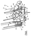
- alternating linear wiper mechanism 10 and in particular a guide rail 12 made in the form of a longitudinal section, here as a rectilinear example, and a trolley 14 for guiding and driving an organ wiper 20, a portion of which is shown, which is example a wiper arm, a wiper blade, or directly a wiping element in the form of a blade wiper made of flexible material.
- the carriage 14 is constituted essentially by a frame plate 16 which extends horizontally as reference in the figures and which is made in particular by cutting and folding a thick sheet metal plate.
- the carriage 14 From the plate 16, the carriage 14 comprises a connecting lug 18 which extends outside the section 12 and which is folded to be extended by the wiper member 20 represented in silhouette in Figure 3.
- the shaping of the trolley with its chassis plate 16 is such that the horizontal frame plate 16 extends substantially in a plane parallel to the plane of the glass pane wipe (not shown).
- the profile 12 is made for example of metal by extrusion, or extruded or by molding, and it is constituted essentially by a wing continuous and continuous horizontal lower 22 which is delimited vertically upwards by a horizontal top face 24 inside the profile 12.
- the wing 22 comprises, arranged at each of its two opposite transverse ends left and right in considering Figures 1 to 3, two side rails opposites 24 each of which, in cross-section, substantially the shape of an open C transversally to inside the profile 12.
- each slide 24 has a side cheek vertical 26 corresponding to the vertical branch of the C, a horizontal upper wing 28 delimiting a horizontal face internal and lower 30, and a lower horizontal flange 32 which extends in the extension of the main lower wing 22 of the profile.
- the upper inner horizontal face of the wing 32 is actually constituted by the coplanar free upper edges 34 of at least one parallel longitudinal rib 36 which are formed in relief on the inner upper face 24 of the wing 22.
- the inner upper face 24 of the main wing 22 of the profile 12 comprises a rib longitudinal rectilinear 38 which extends vertically in relief upward and which is received, without cross-play, in a complementary straight longitudinal groove 40 arranged under the underside 15 of the frame plate 16.
- the groove 40 is a groove vertically downward opening which is formed in a guiding element 42 which is for example a molded part plastic material reported on the plate 16, for example by overmoulding on the latter.
- the piece 42 has reinforcement ribs 44 so that to prevent it from being deformed, that is to say so that the groove 40 keeps constant transverse dimensions for avoid any play in the horizontal transverse direction in order to guarantee a precise positioning and a good longitudinal guiding of the carriage 14 with respect to the profile 12.
- stabilizing means constituted here by three skids of stabilization 50.
- the stabilizing pads 50 are arranged in a triangle, that is to say that the frame plate 16 carries on one side, to left considering the figures, a central pad 50 received in the guiding slide 24 on the left, while its opposite transverse edge of right door two stabilizing pads 50, spaced longitudinally and which are both received simultaneously in the other guide rail of right 24.
- each guide shoe 50 is preferably constituted by a ring flattened 52 of elastically deformable material, for example elastomer material, which is threaded transversely on a finger 54 constituted by a tab coming from cutting the plate 16.
- Each ring or flattened ring 52 is coated with a layer 56 of low friction material.
- each stabilizing pad 50 is such that it is mounted without play in the vertical direction between the inner faces vis-à-vis upper and lower 30 34 of the C-shaped slide 24 so as to ensure a good guidance and good stabilization of the plate 16 relative to the profile 12.
- each skate 50 having a ring or flattened ring 52 made of elastomeric material, allows temporary cash exceptional efforts applied to the trolley in the direction of tilting around a horizontal axis, while ensuring good sliding guide accuracy in normal use.
- the frame plate 16 of the guide carriage 14 also includes means for ensuring its connection in translation with a flexible element 60 to drive the slide carriage 14 with respect to the profile 12 which is constituted by a cable 60.
- the cable 60 passes over the upper face 17 of the plate 16 and it is mounted tight by two clamps, longitudinally spaced, 62 and by means of orientation screws vertical 64 which pass through the clamps 62 and each of which is mounted screwed through the plate 16 into a lower nut 66 arranged under the lower face 15 of the plate 16.
- the guiding of the carriage 14 by its frame plate 16 inside the profile 12 is accurate in the transverse direction, that is to say without game in this direction, and it is stabilized thanks to the pads 50, and this without resorting to any rotating element such as one or several wheels or wheels as in the state of the technical.
- the invention is applicable to any type of wiper mechanism of the linear scanning type, and especially whatever the orientation of the profile in space, the notion of horizontal orientation having been here chosen with reference to the figures to facilitate description and drafting the claims.
- the invention is not limited to the embodiment which just described.
- the complementary arrangement of the rib 38 and the groove 40 can of course be reversed, that is to say that the groove 40 can be made from material extrusion with the profile 12 while the guide rib is then carried by the underside 15 of the frame plate 16 of the trolley 14.
- the invention is not limited to the choice of materials that have been mentioned previously.
Landscapes
- Engineering & Computer Science (AREA)
- Mechanical Engineering (AREA)
- Bearings For Parts Moving Linearly (AREA)
- Transmission Devices (AREA)
- Extrusion Moulding Of Plastics Or The Like (AREA)
- Cleaning Implements For Floors, Carpets, Furniture, Walls, And The Like (AREA)
- Window Of Vehicle (AREA)
Claims (14)
- Scheibenwischermechanismus (10) mit alternierendem linearen Wischen, von der Art, umfassend:und von der Art, in der die Rahmenplatte (16) längliche Führungsmittel (40) trägt, die mit komplementären Mitteln (38) des Profils (12, 22) zusammenwirken, um die transversale Position der Rahmenplatte (16) im Verhältnis zum Profil (12) zu bestimmen, dadurch gekennzeichnet, dass die Mittel der transversalen Positionierung der Rahmenplatte (16) im Verhältnis zum Profil (12, 22) eine vom Profil (12, 22) oder von der Rahmenplatte getragene steife Rippe (38) länglicher Ausrichtung umfasst, die in länglichem Gleiten in einer komplementären offenen vertikal, von der Rahmenplatte (16) oder jeweils dem Profil getragenen länglichen Rille (40) aufgenommen wird, und dass jedes Stabilisierungselement ein Stabilisierungsfuß (50) ist, der in länglichem Gleiten im Innern der entsprechenden Führung (24) in C-Form aufgenommen wird.einen Führungs- und Antriebsschlitten (14), der wenigstens ein Abwischorgan (20) trägt, insbesondere einen Arm oder einen Scheibenwischer, und der gleitend im Innern einer länglichen steifen Führungsschiene in Form eines hohlen Profils (12) realisiert ist;eine wenigstens teilweise im Innern der Führungsschiene untergebrachte Rahmenplatte (16) des Schlittens (14), die sich in einer horizontalen länglichen, zur Wischebene deutlich parallelen Ebene erstreckt;zwei seitliche entgegen gesetzte offene, transversal, entweder einander gegenüber auf dem hohlen Profil oder auf den seitlichen entgegen gesetzten Rändern der Rahmenplatte (16) ausgesparte Führungen (24) in C-Form;wenigstens ein von den Führungen aufgenommenes und entweder von der Rahmenplatte (16) getragenes oder in Form eines horizontalen, kontinuierlichen Flügels des hohlen Profils realisiertes komplementäres Stabilisierungselement (50);
- Scheibenwischermechanismus gemäß dem vorherigen Anspruch, dadurch gekennzeichnet, dass die Führungsrille (40) zur Rahmenplatte (16) des Schlittens (14) gehört und unter einer unteren Seite (15) dieser Platte (16) angeordnet ist, um gleitend eine im Relief nach oben auf einer inneren Seite (24) des Profils (12, 22) geformten Rippe (38) aufzunehmen.
- Scheibenwischermechanismus gemäß dem vorherigen Anspruch, dadurch gekennzeichnet, dass die Rille (40) zu einem abgeformten Element (42), insbesondere aus auf die Rahmenplatte (16) übertragenem Plastikmaterial, insbesondere in Form eines auf die Platte aufgeformten Elements gehört.
- Scheibenwischermechanismus gemäß einem der vorherigen Ansprüche, dadurch gekennzeichnet, dass jeder Stabilisierungsfuß (50) ohne Spiel gemäß der vertikalen Richtung in der entsprechenden Führung (24) in C-Form aufgenommen wird.
- Mechanismus gemäß dem vorherigen Anspruch, dadurch gekennzeichnet, dass jeder Fuß (50, 52) elastisch verformbar ist, um ein begrenztes Kippen der Rahmenplatte um eine deutlich längliche horizontale Achse zu erlauben.
- Mechanismus gemäß einem der vorherigen Ansprüche, dadurch gekennzeichnet, dass die peripherische äußere Fläche jedes Stabilisierungsfußes (50), der mit den horizontalen inneren parallelen und entgegen gesetzten Seiten (30, 34) der entsprechenden Führung (24) in C-Form zusammenwirken, eine Verkleidung (56) mit geringem Reibungskoeffizienten umfasst.
- Mechanismus gemäß einem der vorherigen Ansprüche, dadurch gekennzeichnet, dass jeder Stabilisierungsfuß (50) eine allgemeine Form eines abgeflachten Rings (52) aufweist, der auf einen Finger (54) der Rahmenplatte montiert ist, der sich transversal im Innern der entsprechenden Führung (24) in C-Form erstreckt.
- Mechanismus gemäß einem der vorherigen Ansprüche, dadurch gekennzeichnet, dass eine der horizontalen inneren parallelen und entgegen gesetzten Seiten der Führung in C-Form (24) durch die koplanaren freien Ränder (34) von zwei länglichen Rippen (32) des Profils (12, 22) gebildet wird.
- Mechanismus gemäß einem der vorherigen Ansprüche, dadurch gekennzeichnet, dass die Rahmenplatte (16) des Schlittens (14) drei dreieckig angeordnete Stabilisierungsfüße (50) trägt, von denen zwei Füße gleitend in einer der Führungen (24) aufgenommen werden, während der dritte Stabilisierungsfuß gleitend in der anderen der beiden Führungen in C-Form aufgenommen wird.
- Mechanismus gemäß einem der vorherigen Ansprüche, dadurch gekennzeichnet, dass die Führungsrippe (38) ohne Spiel gemäß der transversalen Richtung im Innern der komplementären Führungsrille (40) aufgenommen wird.
- Mechanismus gemäß einem der vorherigen Ansprüche, dadurch gekennzeichnet, dass die Rahmenplatte (16) aus ausgeschnittenem, geknicktem und / oder bombiertem Blech realisiert wird.
- Mechanismus gemäß einem der vorherigen Ansprüche, dadurch gekennzeichnet, dass die Rahmenplatte (16) Mittel (62) für ihre Verbindung mit einem elastischen Antriebselement (60) des Schlittens umfasst.
- Mechanismus gemäß einem der vorherigen Ansprüche, dadurch gekennzeichnet, dass das Profil (12) aus einem einzigen Stück insbesondere durch Extrusion oder durch Abformen realisiert wird.
- Mechanismus gemäß einem der vorherigen Ansprüche, dadurch gekennzeichnet, dass das Profil (12) einen kontinuierlichen horizontalen unteren Flügel (22) umfasst, von dem aus sich die Stabilisierungsführungen in C-Form (24) erstrecken und dass die obere Seite des Profils (12) wenigstens einen länglichen Schlitz für den Durchgang der Schiene einer Klaue (18) nach außen umfasst, die die Rahmenplatte (16) mit dem Abwischorgan verbindet.
Applications Claiming Priority (3)
| Application Number | Priority Date | Filing Date | Title |
|---|---|---|---|
| FR9916513A FR2802877B1 (fr) | 1999-12-27 | 1999-12-27 | Mecanisme d'essuie-glace a balayage lineaire alterne comportant des moyens perfectionnes de guidage du chariot dans son rail de guidage |
| FR9916513 | 1999-12-27 | ||
| PCT/FR2000/003627 WO2001047758A1 (fr) | 1999-12-27 | 2000-12-21 | Mecanisme d'essuie-glace a balayage lineaire alterne comportant des moyens perfectionnes de guidage du chariot dans son rail de guidage |
Publications (2)
| Publication Number | Publication Date |
|---|---|
| EP1242271A1 EP1242271A1 (de) | 2002-09-25 |
| EP1242271B1 true EP1242271B1 (de) | 2005-03-23 |
Family
ID=9553858
Family Applications (1)
| Application Number | Title | Priority Date | Filing Date |
|---|---|---|---|
| EP00990089A Expired - Lifetime EP1242271B1 (de) | 1999-12-27 | 2000-12-21 | Linearwischeranlage mit verbessertem führungsmittel des wagens in der führungsscchiene |
Country Status (6)
| Country | Link |
|---|---|
| US (1) | US6694564B2 (de) |
| EP (1) | EP1242271B1 (de) |
| DE (1) | DE60018975T2 (de) |
| ES (1) | ES2240230T3 (de) |
| FR (1) | FR2802877B1 (de) |
| WO (1) | WO2001047758A1 (de) |
Families Citing this family (5)
| Publication number | Priority date | Publication date | Assignee | Title |
|---|---|---|---|---|
| FR2858285B1 (fr) * | 2003-07-29 | 2005-09-30 | Valeo Systemes Dessuyage | Dispositif d'essuyage a balayage lineaire |
| FR2873076B1 (fr) * | 2004-07-19 | 2006-09-15 | Peugeot Citroen Automobiles Sa | Dispositif d'inclinaison de la lame d'un balai d'essuie-glace de vehicule automobile |
| US8615840B1 (en) | 2007-02-28 | 2013-12-31 | Eric Taneda | Surface cleaning system |
| US8307486B2 (en) * | 2008-07-11 | 2012-11-13 | International Business Machines Corporation | Air vent dust scrubber |
| CN108787778B (zh) * | 2018-07-18 | 2024-04-30 | 中国重型机械研究院股份公司 | 一种活动挤压垫循环装置及方法 |
Family Cites Families (9)
| Publication number | Priority date | Publication date | Assignee | Title |
|---|---|---|---|---|
| DE947532C (de) * | 1953-07-30 | 1956-08-16 | Karl Fischer | Scheibenwischer fuer Kraftfahrzeuge |
| DE962317C (de) * | 1954-07-02 | 1957-04-18 | Dr Alois Culen | Vorrichtung zum Wischen von Flaechen, insbesondere Scheibenwischer fuer Fahrzeuge |
| FR1121126A (fr) * | 1955-02-04 | 1956-07-23 | Essuie-glace | |
| GB887114A (en) | 1959-01-14 | 1962-01-17 | Wynn Developments Ltd | Improvements in window or windscreen wiper mechanisms |
| DE1167202B (de) * | 1961-03-14 | 1964-04-02 | Wolfgang Niessen | Scheibenwischvorrichtung fuer die Frontscheibe von Kraftfahrzeugen |
| GB1288091A (de) | 1969-01-03 | 1972-09-06 | ||
| IT8464337V0 (it) * | 1984-06-15 | 1984-06-15 | Cunico Gianni | Supporto lineare per tergicristallo. |
| FR2658460B1 (fr) | 1990-02-22 | 1994-12-02 | Valeo Systemes Dessuyage | Dispositif d'essuie-glace, notamment pour pare-brise de vehicule. |
| DE4234202C2 (de) | 1992-10-10 | 1995-06-14 | Teves Gmbh Alfred | Vorrichtung zum Reinigen von Windschutzscheiben |
-
1999
- 1999-12-27 FR FR9916513A patent/FR2802877B1/fr not_active Expired - Fee Related
-
2000
- 2000-12-21 US US10/169,214 patent/US6694564B2/en not_active Expired - Fee Related
- 2000-12-21 EP EP00990089A patent/EP1242271B1/de not_active Expired - Lifetime
- 2000-12-21 WO PCT/FR2000/003627 patent/WO2001047758A1/fr not_active Ceased
- 2000-12-21 ES ES00990089T patent/ES2240230T3/es not_active Expired - Lifetime
- 2000-12-21 DE DE60018975T patent/DE60018975T2/de not_active Expired - Lifetime
Also Published As
| Publication number | Publication date |
|---|---|
| ES2240230T3 (es) | 2005-10-16 |
| DE60018975D1 (de) | 2005-04-28 |
| US20020189044A1 (en) | 2002-12-19 |
| FR2802877A1 (fr) | 2001-06-29 |
| EP1242271A1 (de) | 2002-09-25 |
| FR2802877B1 (fr) | 2002-02-15 |
| US6694564B2 (en) | 2004-02-24 |
| WO2001047758A1 (fr) | 2001-07-05 |
| DE60018975T2 (de) | 2006-04-06 |
Similar Documents
| Publication | Publication Date | Title |
|---|---|---|
| FR2652324A1 (fr) | Deflecteur d'air a parties mobiles pour dispositif d'essuie-glace, notamment de vehicule automobile. | |
| EP0410854A1 (de) | Beweglicher Luftableiter für Scheibenwischerblatt, insbesondere für Kraftfahrzeug | |
| CA2555037A1 (fr) | Element de liaison de balai d'essuie-glace comportant un logement creux ouvert vers le haut | |
| EP1346874B1 (de) | Einbau einer Beleuchtungseinheit auf Karosserieteile eines Fahrzeugs | |
| EP1874598B1 (de) | Anordnung zur befestigung eines wischerblatts an einem ende eines antriebsarms | |
| EP1242271B1 (de) | Linearwischeranlage mit verbessertem führungsmittel des wagens in der führungsscchiene | |
| EP1591330B1 (de) | Wischblatt für Scheibenwischer eines Kraftfahrzeuges | |
| FR2851976A1 (fr) | Balai d'essuie-glace de vehicules automobiles | |
| FR2665369A1 (fr) | Ski a face superieure convexe variable. | |
| FR2755926A1 (fr) | Essuie-glace comportant des moyens perfectionnes d'accrochage d'une raclette d'essuyage | |
| FR2574603A1 (fr) | Element de barre conductrice a joint de dilatation | |
| EP0753439A1 (de) | Kraftfahrzeug-Scheibenwischer mit Verkleidung zur Abdeckung des ganzen Wischers | |
| FR2557526A1 (fr) | Raclette d'essuie-glace pour vehicule automobile | |
| FR2560570A1 (fr) | Dispositif essuie-glace pour vehicules automobiles notamment | |
| FR2649370A1 (fr) | Dispositif d'essuie-glace pour vehicules | |
| FR2660267A1 (fr) | Essuie-glace carene, notamment pour vehicule automobile. | |
| FR3013652A1 (fr) | Dispositif d'essuie-glace amovible pour le nettoyage manuel de vitres | |
| FR2804923A1 (fr) | Essuie-glace et balai d'essuie-glace perfectionnes | |
| FR2704193A1 (fr) | Essuie-glace de véhicule automobile. | |
| EP1216173B1 (de) | Wechsel-lineares wischersystem mit einer verbesserten vorrichtung zum spannen des kabels | |
| FR2801017A1 (fr) | Mecanisme d'essuie-glace a balayage lineaire alterne comportant un rail de guidage perfectionne | |
| EP1791733B1 (de) | Einstückiger windschutzscheibenwischerarm mit einem quernuten enthaltenden flexiblen zwischenabschnitt | |
| EP1839972A1 (de) | Scheibenwischer für Glasfläche eines Kraftfahrzeugs | |
| FR2537928A3 (fr) | Portiere de vehicule automobile | |
| FR2499008A1 (fr) | Essuie-glace comportant un bras d'essuie-glace soumis a l'action d'un ressort en compression |
Legal Events
| Date | Code | Title | Description |
|---|---|---|---|
| PUAI | Public reference made under article 153(3) epc to a published international application that has entered the european phase |
Free format text: ORIGINAL CODE: 0009012 |
|
| 17P | Request for examination filed |
Effective date: 20020422 |
|
| AK | Designated contracting states |
Kind code of ref document: A1 Designated state(s): AT BE CH CY DE DK ES FI FR GB GR IE IT LI LU MC NL PT SE TR |
|
| RBV | Designated contracting states (corrected) |
Designated state(s): AT BE CH CY DE ES FR GB IT LI |
|
| 17Q | First examination report despatched |
Effective date: 20040420 |
|
| GRAP | Despatch of communication of intention to grant a patent |
Free format text: ORIGINAL CODE: EPIDOSNIGR1 |
|
| RBV | Designated contracting states (corrected) |
Designated state(s): DE ES FR GB IT |
|
| GRAS | Grant fee paid |
Free format text: ORIGINAL CODE: EPIDOSNIGR3 |
|
| GRAA | (expected) grant |
Free format text: ORIGINAL CODE: 0009210 |
|
| AK | Designated contracting states |
Kind code of ref document: B1 Designated state(s): DE ES FR GB IT |
|
| REG | Reference to a national code |
Ref country code: GB Ref legal event code: FG4D Free format text: NOT ENGLISH |
|
| REG | Reference to a national code |
Ref country code: IE Ref legal event code: FG4D Free format text: FRENCH |
|
| REF | Corresponds to: |
Ref document number: 60018975 Country of ref document: DE Date of ref document: 20050428 Kind code of ref document: P |
|
| GBT | Gb: translation of ep patent filed (gb section 77(6)(a)/1977) |
Effective date: 20050617 |
|
| REG | Reference to a national code |
Ref country code: ES Ref legal event code: FG2A Ref document number: 2240230 Country of ref document: ES Kind code of ref document: T3 |
|
| PLBE | No opposition filed within time limit |
Free format text: ORIGINAL CODE: 0009261 |
|
| STAA | Information on the status of an ep patent application or granted ep patent |
Free format text: STATUS: NO OPPOSITION FILED WITHIN TIME LIMIT |
|
| 26N | No opposition filed |
Effective date: 20051227 |
|
| PGFP | Annual fee paid to national office [announced via postgrant information from national office to epo] |
Ref country code: GB Payment date: 20141218 Year of fee payment: 15 Ref country code: ES Payment date: 20141224 Year of fee payment: 15 |
|
| PGFP | Annual fee paid to national office [announced via postgrant information from national office to epo] |
Ref country code: IT Payment date: 20141223 Year of fee payment: 15 Ref country code: DE Payment date: 20141211 Year of fee payment: 15 |
|
| REG | Reference to a national code |
Ref country code: FR Ref legal event code: PLFP Year of fee payment: 16 |
|
| REG | Reference to a national code |
Ref country code: DE Ref legal event code: R119 Ref document number: 60018975 Country of ref document: DE |
|
| GBPC | Gb: european patent ceased through non-payment of renewal fee |
Effective date: 20151221 |
|
| PG25 | Lapsed in a contracting state [announced via postgrant information from national office to epo] |
Ref country code: GB Free format text: LAPSE BECAUSE OF NON-PAYMENT OF DUE FEES Effective date: 20151221 Ref country code: DE Free format text: LAPSE BECAUSE OF NON-PAYMENT OF DUE FEES Effective date: 20160701 |
|
| REG | Reference to a national code |
Ref country code: FR Ref legal event code: PLFP Year of fee payment: 17 |
|
| PG25 | Lapsed in a contracting state [announced via postgrant information from national office to epo] |
Ref country code: IT Free format text: LAPSE BECAUSE OF NON-PAYMENT OF DUE FEES Effective date: 20151221 |
|
| REG | Reference to a national code |
Ref country code: ES Ref legal event code: FD2A Effective date: 20170127 |
|
| PG25 | Lapsed in a contracting state [announced via postgrant information from national office to epo] |
Ref country code: ES Free format text: LAPSE BECAUSE OF NON-PAYMENT OF DUE FEES Effective date: 20151222 |
|
| REG | Reference to a national code |
Ref country code: FR Ref legal event code: PLFP Year of fee payment: 18 |
|
| PGFP | Annual fee paid to national office [announced via postgrant information from national office to epo] |
Ref country code: FR Payment date: 20180102 Year of fee payment: 18 |
|
| PG25 | Lapsed in a contracting state [announced via postgrant information from national office to epo] |
Ref country code: FR Free format text: LAPSE BECAUSE OF NON-PAYMENT OF DUE FEES Effective date: 20181231 |