EP1241760A1 - Kabelführungselement - Google Patents
Kabelführungselement Download PDFInfo
- Publication number
- EP1241760A1 EP1241760A1 EP02005991A EP02005991A EP1241760A1 EP 1241760 A1 EP1241760 A1 EP 1241760A1 EP 02005991 A EP02005991 A EP 02005991A EP 02005991 A EP02005991 A EP 02005991A EP 1241760 A1 EP1241760 A1 EP 1241760A1
- Authority
- EP
- European Patent Office
- Prior art keywords
- cable
- mounting rail
- clamping
- elements
- cable routing
- Prior art date
- Legal status (The legal status is an assumption and is not a legal conclusion. Google has not performed a legal analysis and makes no representation as to the accuracy of the status listed.)
- Granted
Links
- 230000015572 biosynthetic process Effects 0.000 claims abstract description 6
- 239000000725 suspension Substances 0.000 description 4
- 230000005540 biological transmission Effects 0.000 description 2
- 238000000926 separation method Methods 0.000 description 2
- 230000001419 dependent effect Effects 0.000 description 1
- 238000011161 development Methods 0.000 description 1
- 230000018109 developmental process Effects 0.000 description 1
- 239000000428 dust Substances 0.000 description 1
- 239000013013 elastic material Substances 0.000 description 1
- 238000003780 insertion Methods 0.000 description 1
- 230000037431 insertion Effects 0.000 description 1
- 239000002184 metal Substances 0.000 description 1
Images


Classifications
-
- H—ELECTRICITY
- H02—GENERATION; CONVERSION OR DISTRIBUTION OF ELECTRIC POWER
- H02G—INSTALLATION OF ELECTRIC CABLES OR LINES, OR OF COMBINED OPTICAL AND ELECTRIC CABLES OR LINES
- H02G3/00—Installations of electric cables or lines or protective tubing therefor in or on buildings, equivalent structures or vehicles
- H02G3/02—Details
- H02G3/06—Joints for connecting lengths of protective tubing or channels, to each other or to casings, e.g. to distribution boxes; Ensuring electrical continuity in the joint
- H02G3/0608—Joints for connecting non cylindrical conduits, e.g. channels
-
- H—ELECTRICITY
- H02—GENERATION; CONVERSION OR DISTRIBUTION OF ELECTRIC POWER
- H02G—INSTALLATION OF ELECTRIC CABLES OR LINES, OR OF COMBINED OPTICAL AND ELECTRIC CABLES OR LINES
- H02G3/00—Installations of electric cables or lines or protective tubing therefor in or on buildings, equivalent structures or vehicles
- H02G3/02—Details
- H02G3/04—Protective tubing or conduits, e.g. cable ladders or cable troughs
- H02G3/0437—Channels
Definitions
- the present invention relates to a cable guide element for storage or Cable holder.
- Track systems or light strips are used in a variety of ways because they compared to permanently installed or built-in lights, a high degree of flexibility in offer individual planning of lighting structures for specific applications. So track systems consist of several individual elements, which according to the Modular principle can be put together, so that the entire arrangement to the illuminating premises can be adapted.
- the basic structure of a busbar system is formed by mounting rails that lead to the desired structure and the bracket of the Power supply and control lines and the individual lights are used.
- the DIN rails are extremely stable and are usually made of metal.
- U-shaped mounting rails which are open at the bottom and in which the lines for power supply and / or for the transmission of Control signals for the luminaire modules to be attached to the mounting rails run.
- a well-known trunking system in which U-shaped mounting rails for Is used, for example, by the applicant under the name "ZX trunking system" sold.
- the mounting rails can be directly on the ceiling can be attached, alternatively there is also the possibility of attaching them to ropes or hanging chains.
- a cable routing element according to claim 1.
- This contains fastening means according to the invention for fastening the same on the upper side a mounting rail.
- One or more such cable routing elements thus form a cable duct to accommodate these additional cables.
- the Cable management elements as fastening means on clamping projections, which for Intervene in those arranged on the mounting rail and extending in the longitudinal direction Undercuts are provided so that the cable routing elements are simple Can be clipped onto the mounting rail or locked with it.
- Undercuts are often present on the mounting rails anyway, since they are for the Suspension of the mounting rails on ropes or chains can be used.
- the cable routing element is a U-shaped cable duct element formed, which on its central leg Longitudinal and for engaging in the undercuts of the Carrier rail provided clamping projections.
- they are Cable duct elements interrupted at the points where fasteners for Hanging the mounting rail are arranged.
- the cable duct element have an additional separating leg, so that the cable duct into several Areas is divided.
- the cable routing element is a or several U-shaped clamping elements are formed, which on their central legs Have clamping projections for attachment to the mounting rail. To the Side legs of these clamping elements are then attached to elongated side walls form the cable duct.
- This solution enables an interruption of the Cable duct at the points where a mounting for the mounting rail is provided is to get around.
- the side legs of the clamping elements preferably have in turn locking elements on, which is a simple attachment of the side walls enable.
- the clamping elements one Have separating legs for dividing the cable duct.
- the cable routing element can have two separate elongated side parts are formed, each on one long side Have attachment projections provided on the mounting rail. This too Solution enables the formation of a cable duct with continuous side walls.
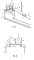
- FIG. 1 and 2 which show the first exemplary embodiment, first show one U-shaped and downwardly open mounting rail 1, which the basic structure of the Busbar system forms.
- mounting rail 1 which the basic structure of the Busbar system forms.
- the entire busbar system is formed, not only the Formation of a single elongated band of light, but also the formation of two or even three-dimensional structures is possible.
- Recording room run the - not shown - lines for power supply and / or transmission of control signals for the individual lights. The lights are placed on the underside of the mounting rail 1.
- the mounting rail 1 itself is by means of a rope 5 and a Fastening bracket 6 attached rope suspension attached to a ceiling.
- the Fastening clip 6 engages on the outside of the middle leg 3 provided undercuts 4 a.
- These undercuts 4 arranged on the upper side of the mounting rail 1 serve also the attachment of several cable routing elements in the form of U-shaped Cable duct elements 7.
- one on the sides of the middle leg 8 Cable duct element 7 provided elongated clamping projections 10, which in attached state of the cable duct element 7 in the undercuts 4 of the Engage mounting rail 1.
- These clamping projections 10 are preferably made of one elastic material, so that the cable duct elements 7 clipped onto the mounting rail or can be snapped into place.
- an upwardly open U-shaped cable duct 11 is formed for receiving additional cable 13 can be used.
- additional cables 13 can it is, for example, telephone cables or fire alarm cables that are used for actual function of the lighting system are not necessary, but one perform another task.
- the cable duct elements 7 shown in FIGS. 1 and 2 also have one additional separating leg 12 through which the cable duct 11 is divided. This can be advantageous in cases where a separation of different Cable harnesses is desirable.
- Cable guide element a continuous cable channel are formed.
- the cable management element from a U-shaped clamping element 14, which - like also has the cable duct elements 7 - on its underside clamping projections 10, the for fastening the clamping element 14 in the undercuts 4 of the Engage mounting rail 1.
- These clamping projections 10 are also preferably elastic, so that a simple clipping or locking with the mounting rail 1 is possible. are the clamping projections 10, however, rigid, the clamping elements 14 in Longitudinal direction are pushed onto the mounting rail 1.
- the two side legs 16 of the clamping element 14 each have two Locking elements 17, which serve to hold elongated side walls 21.
- both side walls 21 form the U-shaped cable duct 11 for receiving the cable 13, the bracket of the side walls 21 each having two with the the two locking elements 17 interacting clamping projections 22.
- the cable channel 11 is at least partially from the top closed so that the ingress of dust is suppressed to a certain extent becomes.
- the middle leg 16 of the clamping element 14 is via two bridge connecting parts 20 connected to a T-piece 18, the separating leg 19 pointing upwards again for a separation of the cable runs arranged in the cable duct 11 provides. Allow the two upward bridge connecting parts 20 also attaching a cable tie through which the cable strands 13 to the Clamping elements 14 can be attached. On the top of the side legs 16 and the clamping element 14 are finally arranged two projections 24 which are each funnel-like inclined inwards, so that easy insertion of Cable strands 13 allows, however, a random slipping out to the top is prevented.
- the Clamping elements 14 are attached to the top of the mounting rails 1. Subsequently the cable strands 13 can be laid and finally through the side walls 21 be enclosed.
- the side walls 21 can also be used in such places be arranged on which a mounting bracket 6 for suspension of the mounting rail 1 is provided. The only condition is that the clamping elements 14 are not on the same places as the mounting brackets 6. So there is Possibility of a closed over the entire length of the mounting rail 1 Cable duct 11 to form.
- a continuous cable duct 11 can also be used in that shown in FIGS. 5 and 6 third embodiment are formed.
- this embodiment there is the cable management element from two elongated side parts 25, which are on the inside in the lower area the clamping elements 10 provided for fastening in the form of have elastic tabs 26. Together with arranged at the bottom Support struts 27 ensure the two tabs 26 for jamming the side parts 25 with the profile of the mounting rail 1.
- the side parts 25 can also in the area on the Carrier rail 1 are attached in the mounting brackets 6 for hanging the Support rail 1 are arranged.
- an entire Length of the mounting rail 1 closed cable duct 11 are formed.
- the cable routing element according to the invention thus offers the possibility of Top of the mounting rail to form another channel that is used for the recording additional cables or the like can be used.
- This channel can go through few handles are formed by the inventive Cable management elements simply placed or clamped onto the mounting rail become.
Landscapes
- Engineering & Computer Science (AREA)
- Architecture (AREA)
- Civil Engineering (AREA)
- Structural Engineering (AREA)
- Installation Of Indoor Wiring (AREA)
- Cable Accessories (AREA)
- Communication Cables (AREA)
- Endoscopes (AREA)
- Details Of Indoor Wiring (AREA)
Abstract
Description
- Fig. 1
- ein erstes Ausführungsbeispiel eines erfindungsgemäßen Kabelführungselements zum Bilden des Kabelkanals in perspektivischer Darstellung;
- Fig. 2
- das in Fig. 1 dargestellte Ausführungsbeispiel im Schnitt;
- Fig. 3
- ein zweites Ausführungsbeispiel eines erfindungsgemäßen Kabelführungselements in perspektivischer Darstellung;
- Fig. 4
- das zweite Ausführungsbeispiel im Schnitt;
- Fig. 5
- ein drittes Ausführungsbeispiel, bei dem das Kabelführungselement durch zwei separate längliche Seitenteile gebildet wird, in perspektivischer Darstellung; und
- Fig. 6
- das dritte Ausführungsbeispiel im Schnitt.
Claims (9)
- Kabelführungselement,
dadurch gekennzeichnet, daß dieses mit Befestigungsmitteln (10) zum Befestigen desselben auf der Oberseite einer Tragschiene (1) zum modularen Bilden eines Stromschienensystems für Leuchten versehen ist. - Kabelführungselement nach Anspruch 1,
dadurch gekennzeichnet, daß dieses als Befestigungsmittel Klemmvorsprünge (10) aufweist, welche zum Eingreifen in an der Tragschiene (1) angeordnete und in Längsrichtung verlaufenden Hinterschneidungen (4) vorgesehen sind. - Kabelführungselement nach Anspruch 2,
dadurch gekennzeichnet, daß dieses durch ein U-förmiges Kabelkanal-Element (7) gebildet wird, das an seinem Mittelschenkel (8) die in Längsrichtung verlaufenden und zum Eingreifen in die Hinterschneidungen (4) der Tragschiene (1) vorgesehenen Klemmvorsprünge (10) aufweist. - Kabelführungselement nach Anspruch 3,
dadurch gekennzeichnet, daß das Kabelkanal-Element (7) einen Trennschenkel (12) zur Teilung des Kabelkanals (11) aufweist. - Kabelführungselement nach Anspruch 2,
dadurch gekennzeichnet, daß dieses durch ein oder mehrere U-förmige Klemmelemente (14) gebildet wird, welche an ihrem Mittelschenkel (15) die Klemmvorsprünge (10) zur Befestigung an der Tragschiene (1) aufweisen, wobei an den Seitenschenkeln (16) der Klemmelemente (14) längliche Seitenwände (21) befestigt sind. - Kabelführungselement nach Anspruch 5,
dadurch gekennzeichnet, daß die Seitenschenkel (16) der Klemmelemente (14) Verrastelemente (17) zum Befestigen der länglichen Seitenwände (21) aufweisen. - Kabelführungselement nach Anspruch 5 oder 6,
dadurch gekennzeichnet, daß die Klemmelemente (14) einen zusätzlichen Trennschenkel (19) aufweisen. - Kabelführungselement nach Anspruch 2,
dadurch gekennzeichnet, daß dieses durch zwei längliche Seitenteile (25) gebildet wird, die jeweils an einer Längsseite die zur Befestigung an der Tragschiene (1) vorgesehenen Klemmvorsprünge (10) aufweisen. - Tragschiene (1) zum modularen Bilden eines Stromschienensystems für Leuchten,
dadurch gekennzeichnet, daß an der Oberseite der Tragschiene (1) ein oder mehrere Kabelführungselemente nach einem der vorherigen Ansprüche befestigt sind.
Applications Claiming Priority (2)
| Application Number | Priority Date | Filing Date | Title |
|---|---|---|---|
| DE10112776.6A DE10112776B4 (de) | 2001-03-16 | 2001-03-16 | Kabelführungselement sowie Tragschiene mit einem solchen Kabelführungselement |
| DE10112776 | 2001-03-16 |
Publications (2)
| Publication Number | Publication Date |
|---|---|
| EP1241760A1 true EP1241760A1 (de) | 2002-09-18 |
| EP1241760B1 EP1241760B1 (de) | 2015-05-13 |
Family
ID=7677766
Family Applications (1)
| Application Number | Title | Priority Date | Filing Date |
|---|---|---|---|
| EP20020005991 Expired - Lifetime EP1241760B1 (de) | 2001-03-16 | 2002-03-15 | Kabelführungselement |
Country Status (3)
| Country | Link |
|---|---|
| EP (1) | EP1241760B1 (de) |
| DE (1) | DE10112776B4 (de) |
| NO (1) | NO330871B1 (de) |
Cited By (7)
| Publication number | Priority date | Publication date | Assignee | Title |
|---|---|---|---|---|
| EP1933434A1 (de) * | 2006-12-14 | 2008-06-18 | BTICINO S.p.A. | An der Decke aufgehängter Kabelkanal und entsprechendes Zubehör |
| WO2012146636A3 (de) * | 2011-04-28 | 2013-01-10 | Zumtobel Lighting Gmbh | Lichtbandsystem und konvertereinheit hierfür |
| WO2014114757A1 (de) * | 2013-01-25 | 2014-07-31 | Zumtobel Lighting Gmbh | Lichtbandsystem |
| CN104242185A (zh) * | 2014-09-18 | 2014-12-24 | 张家港固耐特围栏系统有限公司 | 一种围栏分体式线槽 |
| CN107846802A (zh) * | 2017-12-15 | 2018-03-27 | 无锡优耐特能源科技有限公司 | 一种用于机箱进线的电缆导引装置 |
| IT201700048145A1 (it) * | 2017-05-04 | 2018-11-04 | Rimani S R L | Supporto a parete per dispositivi di illuminazione ed elementi a pannello. |
| WO2021069369A1 (de) * | 2019-10-08 | 2021-04-15 | Zumtobel Lighting Gmbh | Länglicher adapter für ein längliches tragprofil einer länglichen tragschiene |
Families Citing this family (3)
| Publication number | Priority date | Publication date | Assignee | Title |
|---|---|---|---|---|
| DE202018104139U1 (de) * | 2018-07-18 | 2019-10-21 | Vauth-Sagel Holding Gmbh & Co. Kg | Stellwand und Stellwandsystem |
| DE102018123132A1 (de) * | 2018-09-20 | 2020-03-26 | Zumtobel Lighting Gmbh | System zum Anbau an eine abgehängte Stromschiene sowie Verfahren zum Anbau des Systems an eine Stromschiene |
| DE102023132527A1 (de) * | 2023-11-22 | 2025-05-22 | Zumtobel Lighting Gmbh | Stromschienenelement, Tragschienensystem, Transportanordnung und Verpackungsanordnung |
Citations (2)
| Publication number | Priority date | Publication date | Assignee | Title |
|---|---|---|---|---|
| FR1551204A (de) * | 1967-11-15 | 1968-12-27 | ||
| DE9003119U1 (de) * | 1990-03-16 | 1990-05-17 | Grad, Kurt, 8196 Eurasburg | Installationskanalanordnung |
Family Cites Families (4)
| Publication number | Priority date | Publication date | Assignee | Title |
|---|---|---|---|---|
| DE1112771B (de) * | 1958-06-07 | 1961-08-17 | Albert Theysohn | Kabelfuehrungskanal |
| EP0161226B1 (de) * | 1984-04-05 | 1991-02-27 | Handelsbolaget under Firma Elof Hansson | Installationskanal und Montagekonsole dafür |
| DE8602883U1 (de) * | 1986-02-05 | 1987-05-27 | Horst Warneke, Vermietungen und Verpachtungen, 2819 Thedinghausen | Versorgungs- und Verteilerkanal für elektrische Kommunikationseinrichtungen |
| AT411486B (de) * | 2001-01-26 | 2004-01-26 | Wien Kanal Abwassertech Gmbh | Vorrichtung zur befestigung von leitungen |
-
2001
- 2001-03-16 DE DE10112776.6A patent/DE10112776B4/de not_active Expired - Fee Related
-
2002
- 2002-03-13 NO NO20021238A patent/NO330871B1/no not_active IP Right Cessation
- 2002-03-15 EP EP20020005991 patent/EP1241760B1/de not_active Expired - Lifetime
Patent Citations (2)
| Publication number | Priority date | Publication date | Assignee | Title |
|---|---|---|---|---|
| FR1551204A (de) * | 1967-11-15 | 1968-12-27 | ||
| DE9003119U1 (de) * | 1990-03-16 | 1990-05-17 | Grad, Kurt, 8196 Eurasburg | Installationskanalanordnung |
Cited By (13)
| Publication number | Priority date | Publication date | Assignee | Title |
|---|---|---|---|---|
| EP1933434A1 (de) * | 2006-12-14 | 2008-06-18 | BTICINO S.p.A. | An der Decke aufgehängter Kabelkanal und entsprechendes Zubehör |
| US9845942B2 (en) | 2011-04-28 | 2017-12-19 | Zumtobel Lighting Gmbh | Light strip system and converter unit therefor |
| WO2012146636A3 (de) * | 2011-04-28 | 2013-01-10 | Zumtobel Lighting Gmbh | Lichtbandsystem und konvertereinheit hierfür |
| CN103493311A (zh) * | 2011-04-28 | 2014-01-01 | 宗拓贝尔照明器材有限公司 | 光带系统及其转换器单元 |
| EP3611807A1 (de) * | 2011-04-28 | 2020-02-19 | Zumtobel Lighting GmbH | Lichtbandsystem und konvertereinheit hierfür |
| WO2014114757A1 (de) * | 2013-01-25 | 2014-07-31 | Zumtobel Lighting Gmbh | Lichtbandsystem |
| CN104937327A (zh) * | 2013-01-25 | 2015-09-23 | 宗拓贝尔照明器材有限公司 | 灯带系统 |
| US10234085B2 (en) | 2013-01-25 | 2019-03-19 | Zumtobel Lighting Gmbh | Lighting strip system |
| CN104242185A (zh) * | 2014-09-18 | 2014-12-24 | 张家港固耐特围栏系统有限公司 | 一种围栏分体式线槽 |
| IT201700048145A1 (it) * | 2017-05-04 | 2018-11-04 | Rimani S R L | Supporto a parete per dispositivi di illuminazione ed elementi a pannello. |
| CN107846802A (zh) * | 2017-12-15 | 2018-03-27 | 无锡优耐特能源科技有限公司 | 一种用于机箱进线的电缆导引装置 |
| CN107846802B (zh) * | 2017-12-15 | 2023-06-23 | 无锡优耐特能源科技有限公司 | 一种用于机箱进线的电缆导引装置 |
| WO2021069369A1 (de) * | 2019-10-08 | 2021-04-15 | Zumtobel Lighting Gmbh | Länglicher adapter für ein längliches tragprofil einer länglichen tragschiene |
Also Published As
| Publication number | Publication date |
|---|---|
| EP1241760B1 (de) | 2015-05-13 |
| NO20021238L (no) | 2002-09-17 |
| NO330871B1 (no) | 2011-08-01 |
| DE10112776A1 (de) | 2002-09-26 |
| DE10112776B4 (de) | 2016-01-21 |
| NO20021238D0 (no) | 2002-03-13 |
Similar Documents
| Publication | Publication Date | Title |
|---|---|---|
| EP2616378B1 (de) | Anordnung aus einer schiene und einem daran befestigten schleifleitungshalter | |
| DE29717449U1 (de) | Halterung für Solarmodule | |
| EP2948710B1 (de) | Lichtbandsystem | |
| EP3196538B1 (de) | Lichtbandsystem mit einer anordnung zum bilden eines länglichen aufnahmeraums für beleuchtungseinheiten | |
| EP3653925A1 (de) | Abgedichtete leuchte | |
| EP1241760B1 (de) | Kabelführungselement | |
| DE202016100265U1 (de) | Anordnung zum Bilden eines länglichen Aufnahmeraums für Beleuchtungseinheiten | |
| DE102009037764A1 (de) | Stromschienensystem mit doppelseitigem Abgriff | |
| DE8707282U1 (de) | Niedervolt-Stromschiene | |
| EP2858189A1 (de) | Trennvorrichtung für Kabelbahnen und Kabelbahn | |
| DE60301931T2 (de) | Verbesserte Trageeinrichtung für Drahtgitterkanal mit Schnellkupplung | |
| EP1674790B1 (de) | Befestigungssystem zur Montage von Leuchten in einem Lichtband | |
| DE202009015319U1 (de) | Kabelhalter für eine Montageschiene | |
| EP1361632B1 (de) | Trägerelement für Kontaktfederelemente | |
| DE3214596A1 (de) | Aufhaengevorrichtung fuer leuchten | |
| DE1166316B (de) | Fuer die Aufnahme von Leitungen bestimmter Traeger | |
| DE4416110A1 (de) | Tragschiene mit Geräteträger für elektrische Installationen und Leuchtmittel | |
| DE3016064A1 (de) | Tragschiene als bausatzteil fuer die erstellung abgehaengter decken o.dgl. | |
| EP1580858A2 (de) | Kabelhalter | |
| EP0491245A1 (de) | Trägereinheit für Anschlussleisten eines Verteilers in Telekommunikationsanlagen | |
| EP1229622B1 (de) | Abschlusskappe für eine Tragschiene | |
| DE8508070U1 (de) | Tragschiene für Hängebahnen | |
| DE102011103147A1 (de) | Kettenglied für eine Energieführungskette | |
| DE9407583U1 (de) | Tragschiene mit Geräteträger für elektrische Installationen und Leuchtmittel | |
| DE102010000095A1 (de) | System zum Erstellen von Balkonen |
Legal Events
| Date | Code | Title | Description |
|---|---|---|---|
| PUAI | Public reference made under article 153(3) epc to a published international application that has entered the european phase |
Free format text: ORIGINAL CODE: 0009012 |
|
| AK | Designated contracting states |
Kind code of ref document: A1 Designated state(s): AT BE CH CY DE DK ES FI FR GB GR IE IT LI LU MC NL PT SE TR |
|
| AX | Request for extension of the european patent |
Free format text: AL;LT;LV;MK;RO;SI |
|
| 17P | Request for examination filed |
Effective date: 20030311 |
|
| AKX | Designation fees paid |
Designated state(s): AT BE CH CY DE DK ES FI FR GB GR IE IT LI LU MC NL PT SE TR |
|
| RAP1 | Party data changed (applicant data changed or rights of an application transferred) |
Owner name: ZUMTOBEL LIGHTING GMBH |
|
| 17Q | First examination report despatched |
Effective date: 20131016 |
|
| GRAP | Despatch of communication of intention to grant a patent |
Free format text: ORIGINAL CODE: EPIDOSNIGR1 |
|
| INTG | Intention to grant announced |
Effective date: 20141119 |
|
| GRAP | Despatch of communication of intention to grant a patent |
Free format text: ORIGINAL CODE: EPIDOSNIGR1 |
|
| INTG | Intention to grant announced |
Effective date: 20141219 |
|
| GRAS | Grant fee paid |
Free format text: ORIGINAL CODE: EPIDOSNIGR3 |
|
| GRAA | (expected) grant |
Free format text: ORIGINAL CODE: 0009210 |
|
| AK | Designated contracting states |
Kind code of ref document: B1 Designated state(s): AT BE CH CY DE DK ES FI FR GB GR IE IT LI LU MC NL PT SE TR |
|
| REG | Reference to a national code |
Ref country code: GB Ref legal event code: FG4D Free format text: NOT ENGLISH |
|
| REG | Reference to a national code |
Ref country code: CH Ref legal event code: EP |
|
| REG | Reference to a national code |
Ref country code: CH Ref legal event code: NV Representative=s name: WEINMANN ZIMMERLI, CH |
|
| REG | Reference to a national code |
Ref country code: IE Ref legal event code: FG4D Free format text: LANGUAGE OF EP DOCUMENT: GERMAN |
|
| REG | Reference to a national code |
Ref country code: AT Ref legal event code: REF Ref document number: 727132 Country of ref document: AT Kind code of ref document: T Effective date: 20150615 |
|
| REG | Reference to a national code |
Ref country code: DE Ref legal event code: R096 Ref document number: 50216053 Country of ref document: DE Effective date: 20150625 |
|
| REG | Reference to a national code |
Ref country code: NL Ref legal event code: MP Effective date: 20150513 |
|
| PG25 | Lapsed in a contracting state [announced via postgrant information from national office to epo] |
Ref country code: PT Free format text: LAPSE BECAUSE OF FAILURE TO SUBMIT A TRANSLATION OF THE DESCRIPTION OR TO PAY THE FEE WITHIN THE PRESCRIBED TIME-LIMIT Effective date: 20150914 Ref country code: ES Free format text: LAPSE BECAUSE OF FAILURE TO SUBMIT A TRANSLATION OF THE DESCRIPTION OR TO PAY THE FEE WITHIN THE PRESCRIBED TIME-LIMIT Effective date: 20150513 Ref country code: FI Free format text: LAPSE BECAUSE OF FAILURE TO SUBMIT A TRANSLATION OF THE DESCRIPTION OR TO PAY THE FEE WITHIN THE PRESCRIBED TIME-LIMIT Effective date: 20150513 |
|
| PG25 | Lapsed in a contracting state [announced via postgrant information from national office to epo] |
Ref country code: GR Free format text: LAPSE BECAUSE OF FAILURE TO SUBMIT A TRANSLATION OF THE DESCRIPTION OR TO PAY THE FEE WITHIN THE PRESCRIBED TIME-LIMIT Effective date: 20150814 |
|
| PG25 | Lapsed in a contracting state [announced via postgrant information from national office to epo] |
Ref country code: DK Free format text: LAPSE BECAUSE OF FAILURE TO SUBMIT A TRANSLATION OF THE DESCRIPTION OR TO PAY THE FEE WITHIN THE PRESCRIBED TIME-LIMIT Effective date: 20150513 |
|
| REG | Reference to a national code |
Ref country code: DE Ref legal event code: R097 Ref document number: 50216053 Country of ref document: DE |
|
| PLBE | No opposition filed within time limit |
Free format text: ORIGINAL CODE: 0009261 |
|
| STAA | Information on the status of an ep patent application or granted ep patent |
Free format text: STATUS: NO OPPOSITION FILED WITHIN TIME LIMIT |
|
| REG | Reference to a national code |
Ref country code: FR Ref legal event code: PLFP Year of fee payment: 15 |
|
| 26N | No opposition filed |
Effective date: 20160216 |
|
| PG25 | Lapsed in a contracting state [announced via postgrant information from national office to epo] |
Ref country code: IT Free format text: LAPSE BECAUSE OF FAILURE TO SUBMIT A TRANSLATION OF THE DESCRIPTION OR TO PAY THE FEE WITHIN THE PRESCRIBED TIME-LIMIT Effective date: 20150513 |
|
| PGFP | Annual fee paid to national office [announced via postgrant information from national office to epo] |
Ref country code: CH Payment date: 20160324 Year of fee payment: 15 |
|
| PGFP | Annual fee paid to national office [announced via postgrant information from national office to epo] |
Ref country code: FR Payment date: 20160331 Year of fee payment: 15 Ref country code: GB Payment date: 20160331 Year of fee payment: 15 Ref country code: AT Payment date: 20160329 Year of fee payment: 15 |
|
| PG25 | Lapsed in a contracting state [announced via postgrant information from national office to epo] |
Ref country code: BE Free format text: LAPSE BECAUSE OF NON-PAYMENT OF DUE FEES Effective date: 20160331 |
|
| PG25 | Lapsed in a contracting state [announced via postgrant information from national office to epo] |
Ref country code: MC Free format text: LAPSE BECAUSE OF FAILURE TO SUBMIT A TRANSLATION OF THE DESCRIPTION OR TO PAY THE FEE WITHIN THE PRESCRIBED TIME-LIMIT Effective date: 20150513 Ref country code: LU Free format text: LAPSE BECAUSE OF FAILURE TO SUBMIT A TRANSLATION OF THE DESCRIPTION OR TO PAY THE FEE WITHIN THE PRESCRIBED TIME-LIMIT Effective date: 20160315 |
|
| REG | Reference to a national code |
Ref country code: IE Ref legal event code: MM4A |
|
| PG25 | Lapsed in a contracting state [announced via postgrant information from national office to epo] |
Ref country code: IE Free format text: LAPSE BECAUSE OF NON-PAYMENT OF DUE FEES Effective date: 20160315 |
|
| PG25 | Lapsed in a contracting state [announced via postgrant information from national office to epo] |
Ref country code: NL Free format text: LAPSE BECAUSE OF FAILURE TO SUBMIT A TRANSLATION OF THE DESCRIPTION OR TO PAY THE FEE WITHIN THE PRESCRIBED TIME-LIMIT Effective date: 20150513 Ref country code: SE Free format text: LAPSE BECAUSE OF FAILURE TO SUBMIT A TRANSLATION OF THE DESCRIPTION OR TO PAY THE FEE WITHIN THE PRESCRIBED TIME-LIMIT Effective date: 20150513 |
|
| REG | Reference to a national code |
Ref country code: CH Ref legal event code: PL |
|
| REG | Reference to a national code |
Ref country code: AT Ref legal event code: MM01 Ref document number: 727132 Country of ref document: AT Kind code of ref document: T Effective date: 20170315 |
|
| GBPC | Gb: european patent ceased through non-payment of renewal fee |
Effective date: 20170315 |
|
| REG | Reference to a national code |
Ref country code: FR Ref legal event code: ST Effective date: 20171130 |
|
| PG25 | Lapsed in a contracting state [announced via postgrant information from national office to epo] |
Ref country code: FR Free format text: LAPSE BECAUSE OF NON-PAYMENT OF DUE FEES Effective date: 20170331 Ref country code: AT Free format text: LAPSE BECAUSE OF NON-PAYMENT OF DUE FEES Effective date: 20170315 |
|
| PG25 | Lapsed in a contracting state [announced via postgrant information from national office to epo] |
Ref country code: LI Free format text: LAPSE BECAUSE OF NON-PAYMENT OF DUE FEES Effective date: 20170331 Ref country code: CH Free format text: LAPSE BECAUSE OF NON-PAYMENT OF DUE FEES Effective date: 20170331 Ref country code: GB Free format text: LAPSE BECAUSE OF NON-PAYMENT OF DUE FEES Effective date: 20170315 |
|
| PG25 | Lapsed in a contracting state [announced via postgrant information from national office to epo] |
Ref country code: CY Free format text: LAPSE BECAUSE OF FAILURE TO SUBMIT A TRANSLATION OF THE DESCRIPTION OR TO PAY THE FEE WITHIN THE PRESCRIBED TIME-LIMIT Effective date: 20150513 |
|
| PG25 | Lapsed in a contracting state [announced via postgrant information from national office to epo] |
Ref country code: TR Free format text: LAPSE BECAUSE OF FAILURE TO SUBMIT A TRANSLATION OF THE DESCRIPTION OR TO PAY THE FEE WITHIN THE PRESCRIBED TIME-LIMIT Effective date: 20150513 |
|
| REG | Reference to a national code |
Ref country code: DE Ref legal event code: R084 Ref document number: 50216053 Country of ref document: DE |
|
| PGFP | Annual fee paid to national office [announced via postgrant information from national office to epo] |
Ref country code: DE Payment date: 20210329 Year of fee payment: 20 |
|
| REG | Reference to a national code |
Ref country code: DE Ref legal event code: R071 Ref document number: 50216053 Country of ref document: DE |