EP1241408B1 - Brenner für ein Brennstoffgemisch aus Luft und Gas - Google Patents
Brenner für ein Brennstoffgemisch aus Luft und Gas Download PDFInfo
- Publication number
- EP1241408B1 EP1241408B1 EP20010129919 EP01129919A EP1241408B1 EP 1241408 B1 EP1241408 B1 EP 1241408B1 EP 20010129919 EP20010129919 EP 20010129919 EP 01129919 A EP01129919 A EP 01129919A EP 1241408 B1 EP1241408 B1 EP 1241408B1
- Authority
- EP
- European Patent Office
- Prior art keywords
- labyrinth
- fan
- flue gas
- burner
- burner according
- Prior art date
- Legal status (The legal status is an assumption and is not a legal conclusion. Google has not performed a legal analysis and makes no representation as to the accuracy of the status listed.)
- Expired - Lifetime
Links
- 239000000203 mixture Substances 0.000 title claims description 10
- 239000007789 gas Substances 0.000 claims description 24
- 238000002485 combustion reaction Methods 0.000 claims description 10
- 239000000446 fuel Substances 0.000 claims description 6
- 239000003546 flue gas Substances 0.000 claims 11
- UGFAIRIUMAVXCW-UHFFFAOYSA-N Carbon monoxide Chemical compound [O+]#[C-] UGFAIRIUMAVXCW-UHFFFAOYSA-N 0.000 claims 8
- 239000003570 air Substances 0.000 description 8
- 230000001105 regulatory effect Effects 0.000 description 2
- 239000012080 ambient air Substances 0.000 description 1
- 238000010276 construction Methods 0.000 description 1
- 230000002542 deteriorative effect Effects 0.000 description 1
- 239000012530 fluid Substances 0.000 description 1
- 239000007788 liquid Substances 0.000 description 1
- 150000003071 polychlorinated biphenyls Chemical class 0.000 description 1
- 238000002360 preparation method Methods 0.000 description 1
- 230000006641 stabilisation Effects 0.000 description 1
- 238000011105 stabilization Methods 0.000 description 1
Images
Classifications
-
- F—MECHANICAL ENGINEERING; LIGHTING; HEATING; WEAPONS; BLASTING
- F23—COMBUSTION APPARATUS; COMBUSTION PROCESSES
- F23M—CASINGS, LININGS, WALLS OR DOORS SPECIALLY ADAPTED FOR COMBUSTION CHAMBERS, e.g. FIREBRIDGES; DEVICES FOR DEFLECTING AIR, FLAMES OR COMBUSTION PRODUCTS IN COMBUSTION CHAMBERS; SAFETY ARRANGEMENTS SPECIALLY ADAPTED FOR COMBUSTION APPARATUS; DETAILS OF COMBUSTION CHAMBERS, NOT OTHERWISE PROVIDED FOR
- F23M9/00—Baffles or deflectors for air or combustion products; Flame shields
- F23M9/003—Baffles or deflectors for air or combustion products; Flame shields in flue gas ducts
-
- F—MECHANICAL ENGINEERING; LIGHTING; HEATING; WEAPONS; BLASTING
- F23—COMBUSTION APPARATUS; COMBUSTION PROCESSES
- F23D—BURNERS
- F23D14/00—Burners for combustion of a gas, e.g. of a gas stored under pressure as a liquid
- F23D14/02—Premix gas burners, i.e. in which gaseous fuel is mixed with combustion air upstream of the combustion zone
- F23D14/04—Premix gas burners, i.e. in which gaseous fuel is mixed with combustion air upstream of the combustion zone induction type, e.g. Bunsen burner
- F23D14/10—Premix gas burners, i.e. in which gaseous fuel is mixed with combustion air upstream of the combustion zone induction type, e.g. Bunsen burner with elongated tubular burner head
-
- F—MECHANICAL ENGINEERING; LIGHTING; HEATING; WEAPONS; BLASTING
- F23—COMBUSTION APPARATUS; COMBUSTION PROCESSES
- F23L—SUPPLYING AIR OR NON-COMBUSTIBLE LIQUIDS OR GASES TO COMBUSTION APPARATUS IN GENERAL ; VALVES OR DAMPERS SPECIALLY ADAPTED FOR CONTROLLING AIR SUPPLY OR DRAUGHT IN COMBUSTION APPARATUS; INDUCING DRAUGHT IN COMBUSTION APPARATUS; TOPS FOR CHIMNEYS OR VENTILATING SHAFTS; TERMINALS FOR FLUES
- F23L17/00—Inducing draught; Tops for chimneys or ventilating shafts; Terminals for flues
- F23L17/005—Inducing draught; Tops for chimneys or ventilating shafts; Terminals for flues using fans
Definitions
- the invention relates to a burner for a fuel mixture of air and gas, wherein the fuel mixture can be supplied by means of a valve arranged in a combustion chamber burner element and in which the resulting exhaust gases during combustion via a heat exchanger, an exhaust chamber and an exhaust system are derivable.
- the EP 0 655 579 A shows a fan assisted combustion heater having a device for flame stabilization.
- the combustion air flow is at least partially decoupled from the gas-air mixture flow and from the flame zone by means of shielding walls around the burner surface.
- a flow decoupling also shows the US Pat. No. 6,082,993 A , Here, the combustion air flowing into the zone of the gas-air mixture preparation combustion air is decoupled by an aperture-like device of the air surrounding the burner.
- This object is achieved according to the invention in that the exiting from the heat exchanger exhaust gases collected through an exhaust manifold and guided over a labyrinth with baffles a downstream fan can be fed and that the output of the fan is coupled to the exhaust system.
- the flame pattern is more uniform despite the discharge of the exhaust gas by means of the blower, which is associated with an improvement of the emission values.
- the blower ensures a clear discharge of the exhaust gas and can be adjusted with the blower and adjusted sufficiently effectively.
- the labyrinth with the PCBs acts to heat transfer and flame out as train interruption and as a targeted guidance of the exhaust gas to the blower.
- the exhaust gas collector has an inlet opening which completely covers the outlet openings of the heat exchanger and that the reduced outlet opening in cross-section of the exhaust collector is coupled to the input opening of the labyrinth. In this way, the exhaust gas leaving the heat exchanger is detected in its entirety and fed specifically guided the labyrinth.
- the labyrinth is preferably designed so that the labyrinth is formed by alternately directed baffles, which are mounted on the labyrinth housing and aligned horizontally.
- a further embodiment provides that the outlet of the labyrinth be connected to an axial inlet of the blower and a radial outlet of the blower to the exhaust duct.
- the leadership of the exhaust gas in the labyrinth takes place according to an embodiment in such a way that it enters the labyrinth led vertically and leaves this led horizontally.
- the fan may be housed in the exhaust chamber, which may also be associated with the exhaust system.
- a valve 11 is arranged in the lower region, is made and regulated by the supply of air and gas and the mixture of both media to the fuel mixture.
- the switching on and off of the burner can be done in a conventional manner, with the necessary components in the device housing 10 may be accommodated.
- the fitting 11 leads via the feed line 12, the fuel mixture to a burner element 13 where it is burned.
- the hot exhaust gas passes through a heat exchanger 14 and releases its heat energy to the liquid flowing through the heat exchanger 14.
- the heat exchanger 14 may have one or more separate fluid circuits and may be designed in different construction.
- the exhaust gas collector 17 has a reduced cross-section outlet opening 19, which also forms the entrance opening of a labyrinth 20.
- a labyrinth 20 In the housing of the labyrinth 20 alternately directed against each other horizontal baffles 21 and 22 are mounted, which pass the supplied exhaust gases from the exhaust manifold 17 to a fan 30. It is important to ensure that the last of the fan 30 facing baffle 22 is positioned as possible by the fan 30 pioneering in the labyrinth 20 and so acts like a train interruption in the direction of the heat exchanger 14 and arranged in the combustion chamber burner element 13 with the upcoming flame. With the blower 30, therefore, the exhaust gas leaving the labyrinth 20 can be safely supplied to the exhaust duct 40 without impairing the flame stability. The burner can therefore be operated despite fan-assisted removal of the exhaust gas with a uniform flame pattern and low emission values.
- the first baffle 21 facing the exhaust manifold 17 is mounted in the opposite direction to the baffle 22 in the housing of the labyrinth 20 and is used with the reduction of the cross section of the outlet opening 19 of the exhaust manifold 17.
- the output 23 of the labyrinth 20 is connected to an axial input 31 of the blower 30 and leads the exhaust gas via a radial outlet 32 directly the vertically continuing exhaust duct 40 to.
- a motor 33 takes over the drive of the blower 30, which can be switched on and off via an associated control circuit and optionally regulated in its delivery rate.
- the exhaust manifold 17, the labyrinth 20 and the fan 30 with the motor 33 are housed in a section 35 which connects in the device housing 10 via the heat exchanger 14.
- the exhaust gas guide 40 is on the top wall of the device housing 10 and can be connected in a known manner and continued.
- burner 13, combustion chamber, heat exchanger 14, exhaust manifold 17, blower 30 and exhaust connection may be included and sealed against the ambient air.
- the burner can be provided and operated in a known manner with ignition device, exhaust gas recirculation and the like.
Landscapes
- Engineering & Computer Science (AREA)
- Chemical & Material Sciences (AREA)
- Combustion & Propulsion (AREA)
- Mechanical Engineering (AREA)
- General Engineering & Computer Science (AREA)
- Regulation And Control Of Combustion (AREA)
- Gas Burners (AREA)
Description
- Die Erfindung betrifft einen Brenner für ein Brennstoffgemisch aus Luft und Gas, bei dem das Brennstoffgemisch mittels einer Armatur einem in einer Brennkammer angeordneten Brennerelement zuführbar ist und bei dem die bei der Verbrennung entstehenden Abgase über einen Wärmeübertrager, eine Abgaskammer und einer Abgasführung ableitbar sind.
- Bei den Brennern dieser Art treten insbesondere bei der Flammenstabilität und der Abführung der Abgase Probleme auf. Dabei beeinflussen Maßnahmen zur Verbeserung in der einen oder anderen Problemzone das Kaltstartverhalten, die Emissionen und damit den Wirkungsgrad des Brenners.
- Die
EP 0 655 579 A zeigt ein Heizgerät mit gebläseunterstützter Verbrennung, das eine Vorrichtung zur Flammenstabilisierung aufweist. Hierzu wird der Verbrennungsluftstrom mittels abschirmender Wände rund um die Brenneroberfläche zumindest teilweise vom Gas-Luft-Gemischstrom und von der Flammenzone entkoppelt. - Eine Strömungsentkopplung zeigt auch die
US 6 082 993 A , wobei hier die in die Zone der Gas-Luft-Gemischaufbereitung einströmende Verbrennungsluft durch eine blendenähnliche Vorrichtung von der den Brenner umgebenden Luft abgekoppelt wird. - Es ist Aufgabe der Erfindung, einen Brenner der eingangs erwähnten Art so zu gestalten, dass die Flammenstabilität und die Abführung des Abgases verbessert wird, ohne das Kaltstartverhalten und die Emissionswerte zu verschlechtern.
- Diese Aufgabe wird nach der Erfindung dadurch gelöst, dass die aus dem Wärmeübertrager austretenden Abgase über einen Abgassammler gesammelten und über ein Labyrinth mit Leitblechen geführt einem nachgeordneten Gebläse zuführbar sind und dass der Ausgang des Gebläses mit der Abgasführung gekoppelt ist.
- Mit dem Labrinth wird eine Entkopplung zwischen dem nachgeordneten Gebläse und dem Wärmeüberträger und damit der Flamme vor dem Wärmeübertrager erreicht. Das Flammenbild wird trotz Abführung des Abgases mittels des Gebläses gleichmäßiger, was mit einer Verbesserung der Emissionswerte verbunden ist. Das Gebläse sorgt für eine eindeutige Abführung des Abgases und kann mit dem Gebläse angepasst und ausreichend effektiv eingestellt werden. Das Labyrinth mit den Leiterblechen wirkt dabei zur Wärmeübertragung und Flamme hin als Zugunterbrechung und als gezielte Führug des Abgases zum Gebläse hin.
- Nach einer vorteilhaften Ausgestaltung ist vorgesehen, dass der Abgassammler eine Eintrittsöffnung aufweist, die die Austrittsöffnungen des Wärmeübertragers vollständig überdeckt und dass die im Querschnitt verkleinerte Austrittsöffnung des Abgassammlers mit der Eingangsöffnung des Labyrinths gekoppelt ist. Auf diese Weise wird das den Wärmeübertrager verlassende Abgas in seiner Gesamtheit erfasst und gezielt geführt dem Labyrinth zugeführt.
- Das Labyrinth ist vorzugsweise so ausgebildet, dass das Labyrinth durch abwechselnd gegeneinander gerichtete Leitbleche gebildet ist, die am Labyrinth-Gehäuse angebracht und horizontal ausgerichtet sind.
- Damit das Gebläse das zugeführte Abgas in einfacher Weise an die Abgasführung weiterleiten kann, sieht eine weitere Ausgestaltung vor, dass der Ausgang des Labyrinths mit einem axialen Eingang des Gebläses und ein radialer Ausgang des Gebläses mit der Abgasführung verbunden sind.
- Die Führung des Abgases im Labyrinth erfolgt nach einer Ausgestaltung in der Weise, dass es vertikal geführt in das Labyrinth eintritt und dieses horizontal geführt verläßt.
- Ist nach einer Ausgestaltung vorgesehen, dass das dem Gebläse zugekehrte letzte Leitblech des Labyrinths vom Gebläse wegweist und als eine Art Zugunterbrecher wirkt, dann wirkt das Labyrinth schon unmittelbar im Grenzbereich zum Gebläse als Zugunterbrechung.
- Das Gebläse kann in der Abgaskammer untergebracht sein, die auch mit der Abgasführung vereinigt sein kann.
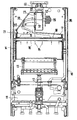
- Die Erfindung wird anhand eines in der Zeichnung dargestellten schematischen Aufbaues eines Brenners mit Labyrinth und Gebläse näher erläutert.
- Wie der Zeichnung zu entnehmen ist, sind alle Teile des Brenners in einem Brennergehäuse untergebracht, wobei im unteren Bereich eine Armatur 11 angeordnet ist, über die Zufuhr von Luft und Gas sowie die Mischung beider Medien zum Brennstoffgemisch vorgenommen und geregelt wird. Die Ein- und Ausschaltung des Brenners kann in an sich bekannter Weise erfolgen, wobei auch die dafür notwendigen Bauteile im Gerätegehäuse 10 untergebracht sein können.
- Die Armatur 11 führt über die Zuleitung 12 das Brennstoffgemisch einem Brennerelement 13 zu, wo dieses verbrannt wird. Das heiße Abgas passiert einen Wärmeübertrager 14 und gibt seine Wärmeenergie an die den Wärmeübertrager 14 durchströmende Flüssigkeit ab. Dabei kann der Wärmeübertrager 14 einen oder mehrere getrennte Flüssigkeitskreise aufweisen und in unterschiedlicher Bauweise ausgeführt sein können.
- Die den Wärmeübertrager 14 über die Ausgänge 16 verlassenden Abgase 15 werden von einem Agassammler 17 vollständig aufgenommen, da dessen Eingangsöffnung 18 alle Ausgänge 16 des Wärmeübertragers 14 überdeckt.
- Der Abgassammler 17 hat eine im Querschnitt reduzierte Austrittsöffnung 19, die gleichzeitig die Eingangsöffnung eines Labyrinths 20 bildet. Im Gehäuse des Labyrinths 20 sind abwechselnd gegeneinander gerichtete horizontale Leitbleche 21 und 22 angebracht, die die zugeleiteten Abgase aus dem Abgassammler 17 geführt an ein Gebläse 30 weiterleiten. Dabei ist darauf zu achten, dass das letzte dem Gebläse 30 zugekehrte Leitblech 22 möglichst vom Gebläse 30 wegweisend im Labyrinth 20 angeordnet ist und so nach Art einer Zugunterbrechung in Richtung zum Wärmeübertrager 14 und dem im Brennraum angeordneten Brennerelement 13 mit der daran anstehenden Flamme wirkt. Mit dem Gebläse 30 kann daher das das Labyrinth 20 verlassende Abgas sicher der Abgasführung 40 zugeführt werden, ohne die Flammenstabilität zu beeinträchtigen. Der Brenner kann daher trotz gebläsegeförderter Abführung des Abgases mit gleichmäßigem Flammbild und niedrigen Emissionswerten betrieben werden.
- Wie das Ausführungsbeispiel zeigt, ist das dem Abgassammler 17 zugekehrte erste Leitblech 21 in Gegenrichtung zum Leitblech 22 im Gehäuse des Labyrinths 20 angebracht und wird mit der Reduzierung des Querschnitts der Austrittsöffnung 19 des Abgassammlers 17 verwendet.
- Der Ausgang 23 des Labyrinths 20 wird mit einem axialen Eingang 31 des Gebläses 30 verbunden und führt das Abgas über einen radialen Ausgang 32 direkt der vertikal weiterführenden Abgasführung 40 zu. Ein Motor 33 übernimmt den Antrieb des Gebläses 30, der über eine zugeordnete Steuerschaltung ein- und ausschaltbar und gegebenenfalls in seiner Förderleistung geregelt werden kann.
- Der Abgassammler 17, das Labyrinth 20 und das Gebläse 30 mit dem Motor 33 sind in einem Abschnitt 35 untergebracht, der sich im Gerätegehäuse 10 über dem Wärmeübertrager 14 anschließt. Die Abgasführung 40 steht an der Deckwand des Gerätegehäuses 10 ab und kann in bekannter Weise angeschlossen und weiter geführt werden. In diesem Gerätegehäuse 10 können Brenner 13, Brennkammer, Wärmeübertrager 14, Abgassammler 17, Gebläse 30 und Abgasanschluss enthalten und gegen die Umgebungsluft abgedichtet sein.
- In dem schematischen Aufbau sind nur die für die Erfindung wesentlichen Teile in Einzelheiten beschrieben. Im Übrigen kann der Brenner in bekannter Weise mit Zündeinrichtung, Abgasrückführung und dergleichen versehen und betrieben werden.
Claims (7)
- Brenner für ein Brennstoffgemisch aus Luft und Gas, bei dem das Brennstoffgemisch mittels einer Armatur (11) einem in einer Brennkammer angeordneten Brennerelement (13) zugeführt wird, und bei dem die bei der Verbrennung entstehenden Abgase (15) über einen Wärmeübertrager (14), eine Abgaskammer und eine Abgasführung (40) abgeleitet werden,
wobei die aus dem Wärmeübertrager (14) austretenden Abgase (15) über einen Abgassammler (17) gesammelt und über ein Labyrinth (20) mit Leitblechen (21, 22) geführt einem nachgeordneten Gebläse (30) zugeführt werden, und wobei der Ausgang (32) des Gebläses (30) mit der Abgasführung (40) gekoppelt ist. - Brenner nach Anspruch 1,
dadurch gekennzeichnet,
dass der Abgassammler (17) eine Eintrittsöffnung (18) aufweist, die die Austrittsöffnungen (16) des Wärmeübertragers (14) vollständig überdeckt und
dass die im Querschnitt verkleinerte Austrittsöffnung (19) des Abgassammlers (17) mit der Eingangsöffnung des Labyrinths (20) gekoppelt ist. - Brenner nach Anspruch 1 oder 2,
dadurch gekennzeichnet,
dass das Labyrinth (20) durch abwechselnd gegeneinander gerichtete Leitbleche (21, 22) gebildet ist, die am Labyrinth-Gehäuse angebracht und horizontal ausgerichtet sind. - Brenner nach einem der Ansprüche 1 bis 3,
dadurch gekennzeichnet,
dass der Ausgang (23) des Labyrinths (20) mit einem axialen Eingang (31) des Gebläses (30) und ein radialer Ausgang (32) des Gebläses (30) mit der Abgasführung (40) verbunden sind. - Brenner nach einem der Ansprüche 1 bis 4,
dadurch gekennzeichnet,
dass die Abgase vertikal geführt in das Labyrinth (20) eintreten und dieses horizontal geführt verlassen. - Brenner nach einem der Ansprüche 1 bis 5,
dadurch gekennzeichnet,
dass das dem Gebläse (30) zugekehrte letzte Leitblech (22) des Labyrinths (20) vom Gebläse (30) wegweist und als eine Art Zugunterbrecher wirkt. - Brenner nach einem der Ansprüche 1 bis 6,
dadurch gekennzeichnet,
dass das Gebläse (30) als Sauggebläse ausgebildet und in einer Abgaskammer bzw. einem Abschnitt (35) des Gerätegehäuses (10) untergebracht ist.
Applications Claiming Priority (2)
| Application Number | Priority Date | Filing Date | Title |
|---|---|---|---|
| DE10112669 | 2001-03-16 | ||
| DE2001112669 DE10112669C2 (de) | 2001-03-16 | 2001-03-16 | Brenner für ein Brennstoffgemisch aus Luft und Gas |
Publications (2)
| Publication Number | Publication Date |
|---|---|
| EP1241408A1 EP1241408A1 (de) | 2002-09-18 |
| EP1241408B1 true EP1241408B1 (de) | 2007-09-12 |
Family
ID=7677702
Family Applications (1)
| Application Number | Title | Priority Date | Filing Date |
|---|---|---|---|
| EP20010129919 Expired - Lifetime EP1241408B1 (de) | 2001-03-16 | 2001-12-15 | Brenner für ein Brennstoffgemisch aus Luft und Gas |
Country Status (2)
| Country | Link |
|---|---|
| EP (1) | EP1241408B1 (de) |
| DE (2) | DE10112669C2 (de) |
Families Citing this family (2)
| Publication number | Priority date | Publication date | Assignee | Title |
|---|---|---|---|---|
| CN107171191B (zh) | 2016-03-07 | 2021-02-26 | Abb瑞士股份有限公司 | 具有互连的排气系统的开关装置封壳 |
| CN111043768A (zh) * | 2019-12-09 | 2020-04-21 | 珠海格力电器股份有限公司 | 一种燃气采暖热水炉控制方法、装置及燃气采暖热水炉 |
Family Cites Families (9)
| Publication number | Priority date | Publication date | Assignee | Title |
|---|---|---|---|---|
| FR2452059A1 (fr) * | 1979-03-21 | 1980-10-17 | Saunier Duval | Dispositif d'evacuation des gaz brules et d'admission d'air frais pour appareils etanches a gaz |
| DE3121220C2 (de) * | 1980-05-28 | 1983-05-11 | Kabushiki Kaisha Youei Seisakusho, Osaka | Wassererhitzer |
| DE3520131C2 (de) * | 1984-09-18 | 1995-05-11 | Bosch Gmbh Robert | Gas- oder ölbeheizter Wassererhitzer |
| AT386475B (de) * | 1986-06-10 | 1988-08-25 | Vaillant Gmbh | Abgas- und zuluftfuehrung fuer einen brennraum |
| DE9015221U1 (de) * | 1990-11-06 | 1991-02-28 | Buderus Heiztechnik GmbH, 6330 Wetzlar | Gasheizkessel mit einem nachgeschalteten Abgasgebläse |
| EP0655579A1 (de) * | 1993-11-25 | 1995-05-31 | Nefit Fasto B.V. | Brenner |
| AT403092B (de) * | 1994-03-25 | 1997-11-25 | Vaillant Gmbh | Wasserheizgerät |
| EP0942240A1 (de) * | 1998-03-13 | 1999-09-15 | Joachim Ferretti | Heizkessel für flüssige, gasförmige und/oder staubförmige Brennstoffe |
| US6082993A (en) * | 1999-05-28 | 2000-07-04 | H-Tech, Inc. | Induced draft heater with premixing burners |
-
2001
- 2001-03-16 DE DE2001112669 patent/DE10112669C2/de not_active Expired - Fee Related
- 2001-12-15 DE DE50112999T patent/DE50112999D1/de not_active Expired - Lifetime
- 2001-12-15 EP EP20010129919 patent/EP1241408B1/de not_active Expired - Lifetime
Also Published As
| Publication number | Publication date |
|---|---|
| EP1241408A1 (de) | 2002-09-18 |
| DE50112999D1 (de) | 2007-10-25 |
| DE10112669C2 (de) | 2003-07-03 |
| DE10112669A1 (de) | 2002-09-26 |
Similar Documents
| Publication | Publication Date | Title |
|---|---|---|
| DE60105093T2 (de) | Brennstoffverdünnungsverfahren und Vorrichtung zur NOx-Verminderung | |
| DE60011541T2 (de) | Verfahren und Vorrichtung zur NOx Reduktion | |
| EP0218047B1 (de) | Vorrichtung zum Regenerieren von Russfiltern | |
| EP0139085A1 (de) | Verfahren und Brenner zum Verbrennen von flüssigen oder gasförmigen Brennstoffen unter verminderter Bildung von NOx | |
| EP1840465A2 (de) | Brennersystem mit gestufter Brennstoff-Eindüsung | |
| EP0769399B1 (de) | Fahrzeugheizgerät | |
| DE3007516A1 (de) | Heizkessel fuer kombinierte oel-/gas- und/oder festbrennstoff-feuerung | |
| WO2022117345A1 (de) | Vorrichtung und verfahren zur verbrennungsluftzufuhr und abgasrezirkulation für einen brenner | |
| DE60224518T2 (de) | Vormischende turbinenverbrennungskammer | |
| CH622878A5 (de) | ||
| DE4113412C2 (de) | Vorrichtung zur Verbrennung von flüssigem oder gasförmigem Brennstoff für eine Feuerungsanlage | |
| DE10112669C2 (de) | Brenner für ein Brennstoffgemisch aus Luft und Gas | |
| EP2442027A2 (de) | Heizgerät und Verfahren zum Betrieb eines Heizgerätes | |
| DE3310500C2 (de) | Brenner zur Verbrennung von staubförmigen Brennstoffen, insbesondere Kohlenstaub | |
| DE2700786C3 (de) | Keramischer Gasbrenner für Winderhitzer | |
| EP1286115A1 (de) | Thermische Nachverbrennungsanlage | |
| DE102004047443B3 (de) | Flachflammenbrenner | |
| EP0829678A2 (de) | Kanalbrenner und Verfahren zum Aufheizen eines strömenden Gases | |
| AT404399B (de) | Verfahren und brenner zum verbrennen insbesondere flüssiger brennstoffe | |
| DE19628710C2 (de) | Vormischender atmosphärischer Gasbrenner | |
| DE102016112103B4 (de) | Hochtemperaturofen mit Wärmerückgewinnung | |
| DE8520263U1 (de) | Durchlauf- oder Speicherwasserheizer | |
| EP0562323B1 (de) | Brenner mit Flammen-Brennrohr | |
| DE3717375A1 (de) | Einrichtung fuer die reinigung von ventilationsausscheidungen | |
| DE892044C (de) | Feuergeschränk, vorzugsweise für Flammrohrkessel |
Legal Events
| Date | Code | Title | Description |
|---|---|---|---|
| PUAI | Public reference made under article 153(3) epc to a published international application that has entered the european phase |
Free format text: ORIGINAL CODE: 0009012 |
|
| AK | Designated contracting states |
Kind code of ref document: A1 Designated state(s): AT BE CH CY DE DK ES FI FR GB GR IE IT LI LU MC NL PT SE TR |
|
| AX | Request for extension of the european patent |
Free format text: AL;LT;LV;MK;RO;SI |
|
| 17P | Request for examination filed |
Effective date: 20030318 |
|
| AKX | Designation fees paid |
Designated state(s): DE FR GB IT |
|
| GRAP | Despatch of communication of intention to grant a patent |
Free format text: ORIGINAL CODE: EPIDOSNIGR1 |
|
| GRAS | Grant fee paid |
Free format text: ORIGINAL CODE: EPIDOSNIGR3 |
|
| GRAA | (expected) grant |
Free format text: ORIGINAL CODE: 0009210 |
|
| AK | Designated contracting states |
Kind code of ref document: B1 Designated state(s): DE FR GB IT |
|
| REG | Reference to a national code |
Ref country code: GB Ref legal event code: FG4D Free format text: NOT ENGLISH |
|
| REF | Corresponds to: |
Ref document number: 50112999 Country of ref document: DE Date of ref document: 20071025 Kind code of ref document: P |
|
| GBT | Gb: translation of ep patent filed (gb section 77(6)(a)/1977) |
Effective date: 20071107 |
|
| ET | Fr: translation filed | ||
| PLBE | No opposition filed within time limit |
Free format text: ORIGINAL CODE: 0009261 |
|
| STAA | Information on the status of an ep patent application or granted ep patent |
Free format text: STATUS: NO OPPOSITION FILED WITHIN TIME LIMIT |
|
| 26N | No opposition filed |
Effective date: 20080613 |
|
| REG | Reference to a national code |
Ref country code: FR Ref legal event code: PLFP Year of fee payment: 15 |
|
| PGFP | Annual fee paid to national office [announced via postgrant information from national office to epo] |
Ref country code: GB Payment date: 20151221 Year of fee payment: 15 |
|
| PGFP | Annual fee paid to national office [announced via postgrant information from national office to epo] |
Ref country code: FR Payment date: 20151218 Year of fee payment: 15 |
|
| PGFP | Annual fee paid to national office [announced via postgrant information from national office to epo] |
Ref country code: DE Payment date: 20160224 Year of fee payment: 15 |
|
| PGFP | Annual fee paid to national office [announced via postgrant information from national office to epo] |
Ref country code: IT Payment date: 20151222 Year of fee payment: 15 |
|
| REG | Reference to a national code |
Ref country code: DE Ref legal event code: R119 Ref document number: 50112999 Country of ref document: DE |
|
| GBPC | Gb: european patent ceased through non-payment of renewal fee |
Effective date: 20161215 |
|
| REG | Reference to a national code |
Ref country code: FR Ref legal event code: ST Effective date: 20170831 |
|
| PG25 | Lapsed in a contracting state [announced via postgrant information from national office to epo] |
Ref country code: IT Free format text: LAPSE BECAUSE OF NON-PAYMENT OF DUE FEES Effective date: 20161215 Ref country code: FR Free format text: LAPSE BECAUSE OF NON-PAYMENT OF DUE FEES Effective date: 20170102 |
|
| PG25 | Lapsed in a contracting state [announced via postgrant information from national office to epo] |
Ref country code: GB Free format text: LAPSE BECAUSE OF NON-PAYMENT OF DUE FEES Effective date: 20161215 Ref country code: DE Free format text: LAPSE BECAUSE OF NON-PAYMENT OF DUE FEES Effective date: 20170701 |