EP1241072B1 - Assemblage d'un étrier de colonne de direction avec un pignon de direction d'un véhicule automobile - Google Patents
Assemblage d'un étrier de colonne de direction avec un pignon de direction d'un véhicule automobile Download PDFInfo
- Publication number
- EP1241072B1 EP1241072B1 EP02290290A EP02290290A EP1241072B1 EP 1241072 B1 EP1241072 B1 EP 1241072B1 EP 02290290 A EP02290290 A EP 02290290A EP 02290290 A EP02290290 A EP 02290290A EP 1241072 B1 EP1241072 B1 EP 1241072B1
- Authority
- EP
- European Patent Office
- Prior art keywords
- antirotation
- clamping
- bearing
- bracket
- nut
- Prior art date
- Legal status (The legal status is an assumption and is not a legal conclusion. Google has not performed a legal analysis and makes no representation as to the accuracy of the status listed.)
- Expired - Lifetime
Links
- 210000002105 tongue Anatomy 0.000 claims description 11
- 238000006386 neutralization reaction Methods 0.000 claims description 4
- 230000003100 immobilizing effect Effects 0.000 claims 3
- 238000003780 insertion Methods 0.000 claims 1
- 230000037431 insertion Effects 0.000 claims 1
- 208000031968 Cadaver Diseases 0.000 description 5
- 230000000903 blocking effect Effects 0.000 description 2
- 238000012423 maintenance Methods 0.000 description 2
- 238000012550 audit Methods 0.000 description 1
Images


Classifications
-
- F—MECHANICAL ENGINEERING; LIGHTING; HEATING; WEAPONS; BLASTING
- F16—ENGINEERING ELEMENTS AND UNITS; GENERAL MEASURES FOR PRODUCING AND MAINTAINING EFFECTIVE FUNCTIONING OF MACHINES OR INSTALLATIONS; THERMAL INSULATION IN GENERAL
- F16B—DEVICES FOR FASTENING OR SECURING CONSTRUCTIONAL ELEMENTS OR MACHINE PARTS TOGETHER, e.g. NAILS, BOLTS, CIRCLIPS, CLAMPS, CLIPS OR WEDGES; JOINTS OR JOINTING
- F16B37/00—Nuts or like thread-engaging members
- F16B37/04—Devices for fastening nuts to surfaces, e.g. sheets, plates
- F16B37/044—Nut cages
-
- B—PERFORMING OPERATIONS; TRANSPORTING
- B62—LAND VEHICLES FOR TRAVELLING OTHERWISE THAN ON RAILS
- B62D—MOTOR VEHICLES; TRAILERS
- B62D1/00—Steering controls, i.e. means for initiating a change of direction of the vehicle
- B62D1/02—Steering controls, i.e. means for initiating a change of direction of the vehicle vehicle-mounted
- B62D1/16—Steering columns
- B62D1/20—Connecting steering column to steering gear
-
- F—MECHANICAL ENGINEERING; LIGHTING; HEATING; WEAPONS; BLASTING
- F16—ENGINEERING ELEMENTS AND UNITS; GENERAL MEASURES FOR PRODUCING AND MAINTAINING EFFECTIVE FUNCTIONING OF MACHINES OR INSTALLATIONS; THERMAL INSULATION IN GENERAL
- F16B—DEVICES FOR FASTENING OR SECURING CONSTRUCTIONAL ELEMENTS OR MACHINE PARTS TOGETHER, e.g. NAILS, BOLTS, CIRCLIPS, CLAMPS, CLIPS OR WEDGES; JOINTS OR JOINTING
- F16B2/00—Friction-grip releasable fastenings
- F16B2/02—Clamps, i.e. with gripping action effected by positive means other than the inherent resistance to deformation of the material of the fastening
- F16B2/18—Clamps, i.e. with gripping action effected by positive means other than the inherent resistance to deformation of the material of the fastening using cams, levers, eccentrics, or toggles
-
- F—MECHANICAL ENGINEERING; LIGHTING; HEATING; WEAPONS; BLASTING
- F16—ENGINEERING ELEMENTS AND UNITS; GENERAL MEASURES FOR PRODUCING AND MAINTAINING EFFECTIVE FUNCTIONING OF MACHINES OR INSTALLATIONS; THERMAL INSULATION IN GENERAL
- F16D—COUPLINGS FOR TRANSMITTING ROTATION; CLUTCHES; BRAKES
- F16D1/00—Couplings for rigidly connecting two coaxial shafts or other movable machine elements
- F16D1/06—Couplings for rigidly connecting two coaxial shafts or other movable machine elements for attachment of a member on a shaft or on a shaft-end
- F16D1/08—Couplings for rigidly connecting two coaxial shafts or other movable machine elements for attachment of a member on a shaft or on a shaft-end with clamping hub; with hub and longitudinal key
- F16D1/0852—Couplings for rigidly connecting two coaxial shafts or other movable machine elements for attachment of a member on a shaft or on a shaft-end with clamping hub; with hub and longitudinal key with radial clamping between the mating surfaces of the hub and shaft
- F16D1/0864—Couplings for rigidly connecting two coaxial shafts or other movable machine elements for attachment of a member on a shaft or on a shaft-end with clamping hub; with hub and longitudinal key with radial clamping between the mating surfaces of the hub and shaft due to tangential loading of the hub, e.g. a split hub
-
- F—MECHANICAL ENGINEERING; LIGHTING; HEATING; WEAPONS; BLASTING
- F16—ENGINEERING ELEMENTS AND UNITS; GENERAL MEASURES FOR PRODUCING AND MAINTAINING EFFECTIVE FUNCTIONING OF MACHINES OR INSTALLATIONS; THERMAL INSULATION IN GENERAL
- F16D—COUPLINGS FOR TRANSMITTING ROTATION; CLUTCHES; BRAKES
- F16D3/00—Yielding couplings, i.e. with means permitting movement between the connected parts during the drive
- F16D3/16—Universal joints in which flexibility is produced by means of pivots or sliding or rolling connecting parts
- F16D3/26—Hooke's joints or other joints with an equivalent intermediate member to which each coupling part is pivotally or slidably connected
- F16D3/38—Hooke's joints or other joints with an equivalent intermediate member to which each coupling part is pivotally or slidably connected with a single intermediate member with trunnions or bearings arranged on two axes perpendicular to one another
- F16D3/382—Hooke's joints or other joints with an equivalent intermediate member to which each coupling part is pivotally or slidably connected with a single intermediate member with trunnions or bearings arranged on two axes perpendicular to one another constructional details of other than the intermediate member
- F16D3/387—Fork construction; Mounting of fork on shaft; Adapting shaft for mounting of fork
-
- F—MECHANICAL ENGINEERING; LIGHTING; HEATING; WEAPONS; BLASTING
- F16—ENGINEERING ELEMENTS AND UNITS; GENERAL MEASURES FOR PRODUCING AND MAINTAINING EFFECTIVE FUNCTIONING OF MACHINES OR INSTALLATIONS; THERMAL INSULATION IN GENERAL
- F16B—DEVICES FOR FASTENING OR SECURING CONSTRUCTIONAL ELEMENTS OR MACHINE PARTS TOGETHER, e.g. NAILS, BOLTS, CIRCLIPS, CLAMPS, CLIPS OR WEDGES; JOINTS OR JOINTING
- F16B2200/00—Constructional details of connections not covered for in other groups of this subclass
- F16B2200/69—Redundant disconnection blocking means
-
- Y—GENERAL TAGGING OF NEW TECHNOLOGICAL DEVELOPMENTS; GENERAL TAGGING OF CROSS-SECTIONAL TECHNOLOGIES SPANNING OVER SEVERAL SECTIONS OF THE IPC; TECHNICAL SUBJECTS COVERED BY FORMER USPC CROSS-REFERENCE ART COLLECTIONS [XRACs] AND DIGESTS
- Y10—TECHNICAL SUBJECTS COVERED BY FORMER USPC
- Y10T—TECHNICAL SUBJECTS COVERED BY FORMER US CLASSIFICATION
- Y10T403/00—Joints and connections
- Y10T403/70—Interfitted members
- Y10T403/7075—Interfitted members including discrete retainer
Definitions
- the present invention relates to the device assembling a stirrup with a shaft, and the invention relates more particularly to assembly device of a column stirrup steering with a steering gear of a vehicle automobile, which constitutes the connection of the steering column with the steering box.
- the bolt makes it possible to tighten the two branches of the caliper against the pinion shaft, in relying on each of the external faces of branches of said stirrup.
- These types of devices assembly require an environment in the vehicle that allows easy access during assembly and tightening; and moreover it is necessary to provide specific tools that allow the correct presentation of the nut during assembly and the engagement of the screw, and that ensures the maintenance in rotation of the nut during tightening.
- these types of fasteners do not guarantee by maintaining clamping when using the vehicle.
- the purpose of the present invention is to propose a device for assembling a column stirrup direction with a pinion steering, which avoids disadvantages described above, and which allows a particularly easy assembly blind in a reduced size and without specific tools, while guaranteeing the permanence of the assembly.
- the Axial prepositioning thrust is built into the anti-rotation elastic support element.
- the stop axial prepositioning is integrated into the stirrup.
- the axial stop of prepositioning is integrated into one of the branches of the attachment portion of the elastic element antirotation support.
- the internal cylindrical end eccentric of the clamping nut is provided with a face inclined relative to the clamping axis, in order to allow the engagement of the tree following a direction parallel to the caliper amounts.
- the internal cylindrical end of the nut is eccentric to the body cylindrical, so that said end inner cylindrical and said cylindrical body a common generator, which is arranged on the side opposite to the shaft with respect to the clamping axis, when the clamping and locking assembly is in unlocked position.
- a particularly interesting application of the invention relates to a steering column of a motor vehicle, in which the caliper is mounted on said steering column and the shaft belongs to the gearbox gearbox.
- the assembly device of a caliper steering column with a steering gear of a motor vehicle thus presents the advantage of allowing an assembly with the nut of clamping, which is held in position; which avoids any risk of loss and allows assembly in blind in a small footprint.
- locked position with nut lock against the shaft guarantees the maintenance in position of the stirrup on the shaft with the required tightening.
- the device of the invention relates to a assembly of a stirrup 1 with a shaft 2 like that is shown in Figures 2 and 15.
- a particularly interesting application of the invention relates to a steering column of a motor vehicle in which caliper 1 is mounted on said steering column, and the shaft 2 belongs to the gearbox gearbox.
- the connecting device which connects the stirrup 1 of the steering column to the shaft 2 of the steering gear, includes a clamping assembly and locking said shaft 2 in the stirrup 1.
- This clamping and blocking assembly is basically constituted by a clamping screw 3, which cooperates with a clamping nut 4 along a clamping axis 6.
- the entire steering column which is not shown in the figures, door at its end lower a universal joint 8 of the type "cardan".
- the universal joint 8 is integral on the one hand with the steering column, and secondly of the caliper 1.
- the steering pinion has an axis 5, which is the axis of the shaft 2.
- the axis 5 is therefore the axis assembly of the stirrup 1 on the shaft 2.
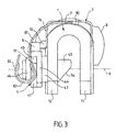
- the stirrup 1 has a cross-section through compared to axis 5, which is U-shaped.
- the stirrup 1 consists of two branches 11 and 12, which are substantially parallel to each other.
- the branches 11 and 12 are connected to each other by a connecting portion 21 which has substantially a circular half-crown section.
- Branches 11 and 12 and the connecting portion 21 constitute the housing 22 of the stirrup 1.
- the portion of connection 21 has an outer face 24 and a face 23, which constitutes the bottom of the housing 22 of the stirrup 1.
- the inner face 23 has a curvature substantially semicircular and of similar size of the circular section of the tree 2.
- Branch 11 has an outer face 17 and a face internal 19, while the branch 12 has a face 18 and an inner face 20.
- a housing 13 is arranged on the outer face 17, and a housing 14 is arranged on the outer face 18.
- Branch 11 is provided with a hole 15, which allows the passage of the screw 3, and the branch 12 has a hole 16 which constitutes the housing and the support of the nut of 4. Holes 15 and 16 are aligned next the clamping axis 6, which is substantially perpendicular to branches 11 and 12, and more precisely to the external faces 17 and 18 and to the faces internal 19 and 20.
- the tree 2 has a circular section with one face cylindrical 25 (see Figure 2).
- a first flat 27 and a second flat 28 are arranged on the shaft 2, and they are substantially parallel one by report to the other.
- the thickness of the shaft 2 between two flats 27 and 28 is substantially adjacent and slightly less than the distance between the two internal faces 19 and 20 of the branches 11 and 12.
- a third flat 26 is arranged on the shaft 2 so that this third flat 26 is substantially perpendicular to the first flat 27 and at the second flat 28.
- the clamping screw 3 has a body 33 with, at one from its ends, a head 31 provided with a collar 32.
- the body 33 is equipped a threaded portion 34 with a tip 35 provided with a transverse face 36.
- the hole 15, which is arranged in the branch 11, is sized to allow free passage the threaded portion 34 of the clamping screw 3, the collar 32 is applied against the face external 17 of the branch 11.
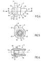
- the tightening nut 4 has a body cylindrical 41 which mounts in the hole 16 of the branch 12 of the stirrup 1.
- the hole 16 is sized so that the cylindrical body 41 fits correctly in said hole 16 of branch 12 which supports the tightening nut 4.
- the cylindrical body 41 is extended by an internal cylindrical end 43 which enters the housing 22 of the stirrup 1.
- the cylindrical body 41 is extended to the outside of branch 12 by a collar 42, which is applied against the outer face 18 of said branch 12.
- the clamping nut 4 is arranged in one of the two branches 12 of the stirrup 1; and the screw 3 crosses the other branch 11 of the stirrup 1.
- the tightening nut 4 is held in place in rotation and translation along the axis of tightening 6, when the clamping and locking assembly is in unlocked position. As shown on FIG. 9, holding in place in rotation and in translation is provided by an elastic element support antirotation 7 of the tightening nut 4.
- the tightening nut 4 is provided with a protrusion radial 9 which is disposed at its outer periphery.
- an axial prepositioning stop 10 is arranged so as to be secured to the stirrup 1.
- the radial protrusion 9 and the axial abutment of prepositioning 10 are designed and arranged to way that, when the radial outgrowth 9 of the tightening nut 4 is applied against the prepositioning axial stop 10, said nut of tightening 4 in a position partially removed along its axis 6 to authorize the commitment of the stirrup 1 on the end of the shaft 2.
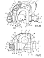
- the anti-rotation elastic element of support 7 is arranged so that at the end of tightening the screw of 3 in the tightening nut 4, said screw tightening 3 neutralises the antirotation function of the anti-rotation elastic element of support 7 (see Figures 12 and 13), to allow the nut to tightening 4 to escape the axial abutment of prepositioning 10 and come jam the caliper 1 on tree 2, as shown on the Figures 14, 2 and 15.
- the axial abutment of prepositioning referenced 101 is integrated with the stirrup 1.
- the axial prepositioning stop 10 is integrated to the elastic antirotation support element 7.
- the attachment portion 71 of the elastic antirotation support element 7 is shaped according to a U-section with two branches 75, 76 and a connection base 74 to to surround the outer part of the stirrup.
- Each of the two branches 75, 76 has a curved end 77, 78 who engages in a housing 13, 14 laid out on the corresponding branch 11, 12 of the stirrup 1.
- the connection flange 74 has two tabs bearing elastics 79 and 80, which are opposite one to the other in the axial direction.
- the antirotation portion of support 72 of the element elastic anti-rotation support 7 has two anti-rotation support tabs 83 and 84, which are connected to each other by an end base 82.
- the flexible link portion 73 of the element elastic antirotation support has two branches flexible 87 and 88 which are connected on the one hand to the connection base 74 of the portion 71 and on the other hand to the tongue corresponding support antirotation 83, 84.
- the axial prepositioning stop 10 is integrated into branch 76 of the snap portion 71 of the elastic support antirotation element 7.
- the clamping nut 4 has a threaded hole 57 which cooperates, with the threaded portion 34.
- a hole passage 56 allows the clamping screw 3 to engage in the tightening nut 4.
- the end cylindrical inner 43 has a cylindrical surface 55 which is eccentric with respect to said cylindrical body 41, so that said cylindrical end internal eccentric 43 is disposed on the opposite side to the shaft 2 relative to the clamping axis 6, when the clamping and locking assembly is in position unlocked (see Figures 8 and 9).
- This eccentricity is arranged so that end of tightening the clamping screw 3 in the nut of tightening 4, and after neutralization of the function antirotation of the antirotation elastic element 7, said clamping nut 4 can rotate around the clamping axis 6, and that the end cylindrical internal eccentric 43 come to rest against the flat 26 arranged on the shaft 2 (see Figures 14 and 15).
- the anti-rotation portion 45 is the extension axial of said cylindrical support base 44. Said anti-rotation portion 45 has two flats 47, 48 : the first flat 47 and the second flat 48 being substantially parallel to each other.
- the outer cylindrical end 46 extends axially the antirotation portion 45, and the transversal size of said end cylindrical outer 46 does not exceed the distance between the first flat 47 and the second flat 48.
- the cylindrical support base 44 has an outer face 51 against which come the two anti-rotation support tongues 83 and 84.
- the portion antirotation 45 has an outer face 52, which must be released at the end of tightening by the anti-rotation portion 72.
- the internal cylindrical end 43 of the nut 4 is eccentric to the body cylindrical 41, so that said end inner cylindrical 43 and said cylindrical body 41 have a common generator 58, which is arranged the opposite side to the shaft 2 with respect to the axis of tightening 6, when the clamping and blocking is in the unlocked position (see figure 9).
- the eccentric internal cylindrical end 43 of the clamping nut 4 is provided with an inclined face 54 relative to the clamping axis 6 to allow the engagement of the tree 2 following a direction parallel to the uprights 11, 12 of the stirrup 1.
- the stirrup 1 thus equipped is engaged on the shaft 2, as shown in Figure 7.
- the tree 2 pushes the inclined face 54 of the end internal cylindrical eccentric 43.
- the tightening nut 4 withdraws to the outside thanks to the flexibility of the elastic antirotation support element 7, and leaves to pass the tree 2 which comes to lean against the face internal 23 of the connecting portion 21.
- the nut clamp 4 then returns to the previous position in support against the axial prepositioning stop 10, as shown in Figure 8.
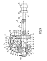
- the screw 3 is then presented along the axis of tightening 6 as shown in Figure 9.
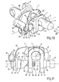
- the clamping screw 4 is then engaged in the branches 11 and 12 and in the through hole 56 of the tightening nut 4 until the flange 32 applies against the outer face 17. During this operation, the clamping screw 3 pushes back the nut tightening outside the stirrup 1, as is shown in Figures 10 and 11.
- the clamping screw 3 then screws into the threaded hole 57 of the tightening nut 4, which move closer to branch 12 until the support antirotation tongue 83 and 84 escape of the anti-rotation portion 45 of the clamping nut 4 (see Figures 12 and 13).
- This release is realized thanks to the action of the transverse face 36 of the end 35 of the clamping screw 3, which pushes back the end base 82 thus causing the anti-rotation support tabs 83 and 84.
- the clamping screw 4 then rotates the tightening nut 4 with its internal end 43, which comes against the flat 26 of the tree 2; and the tightening nut 4 turning, cleared its radial protrusion 9 of the abutment of prepositioning 10, as shown on Figure 14.
Landscapes
- Engineering & Computer Science (AREA)
- General Engineering & Computer Science (AREA)
- Mechanical Engineering (AREA)
- Chemical & Material Sciences (AREA)
- Combustion & Propulsion (AREA)
- Transportation (AREA)
- Clamps And Clips (AREA)
- Steering Controls (AREA)
- Mutual Connection Of Rods And Tubes (AREA)
Applications Claiming Priority (2)
| Application Number | Priority Date | Filing Date | Title |
|---|---|---|---|
| FR0103489 | 2001-03-14 | ||
| FR0103489A FR2822122B1 (fr) | 2001-03-14 | 2001-03-14 | Assemblage d'un etrier de colonne de direction avec un pignon de direction d'un vehicule automobile |
Publications (2)
| Publication Number | Publication Date |
|---|---|
| EP1241072A1 EP1241072A1 (fr) | 2002-09-18 |
| EP1241072B1 true EP1241072B1 (fr) | 2005-06-15 |
Family
ID=8861130
Family Applications (1)
| Application Number | Title | Priority Date | Filing Date |
|---|---|---|---|
| EP02290290A Expired - Lifetime EP1241072B1 (fr) | 2001-03-14 | 2002-02-06 | Assemblage d'un étrier de colonne de direction avec un pignon de direction d'un véhicule automobile |
Country Status (8)
| Country | Link |
|---|---|
| US (1) | US6575658B2 (OSRAM) |
| EP (1) | EP1241072B1 (OSRAM) |
| JP (1) | JP4023185B2 (OSRAM) |
| AT (1) | ATE297861T1 (OSRAM) |
| BR (1) | BR0200641B1 (OSRAM) |
| DE (1) | DE60204613T2 (OSRAM) |
| ES (1) | ES2240667T3 (OSRAM) |
| FR (1) | FR2822122B1 (OSRAM) |
Families Citing this family (23)
| Publication number | Priority date | Publication date | Assignee | Title |
|---|---|---|---|---|
| US7272566B2 (en) * | 2003-01-02 | 2007-09-18 | Dolby Laboratories Licensing Corporation | Reducing scale factor transmission cost for MPEG-2 advanced audio coding (AAC) using a lattice based post processing technique |
| JP2004278698A (ja) * | 2003-03-17 | 2004-10-07 | Koyo Seiko Co Ltd | 軸体と軸継手との結合構造 |
| FR2861041B1 (fr) * | 2003-10-21 | 2006-12-15 | Nacam France Sas | Systeme d'accouplement d'une colonne de direction sur le pignon de la cremaillere de direction |
| JP2005163866A (ja) * | 2003-12-01 | 2005-06-23 | Koyo Seiko Co Ltd | 自在継手用ヨーク |
| US20050169697A1 (en) * | 2004-02-03 | 2005-08-04 | Timken Us Corporation | Adjustable shaft connector |
| ES2257932A1 (es) * | 2004-08-24 | 2006-08-01 | Melchor Daumal Castellon | Conjunto de fijacion para ejes de transmision en horquillas de juntas universales. |
| JP4441600B2 (ja) * | 2005-02-17 | 2010-03-31 | 株式会社ジェイテクト | 誤組付防止具およびこれを含む自在継手 |
| JP4735974B2 (ja) * | 2006-03-30 | 2011-07-27 | 株式会社ジェイテクト | 自在継手のヨークとシャフトとの結合構造 |
| FR2904595B1 (fr) * | 2006-08-02 | 2008-10-17 | Renault Sas | Dispositif de liaison pour systeme de direction. |
| US8231476B2 (en) * | 2006-08-02 | 2012-07-31 | Koyo Machine Industries Co., Ltd. | Yoke for universal joint |
| EP2282920B1 (fr) * | 2008-05-16 | 2011-09-14 | ZF Systemes de Direction Nacam, S.A.S. | Dispositif d'ajustement de position d'une colonne de direction de vehicule automobile |
| US8246658B2 (en) * | 2010-10-29 | 2012-08-21 | Warsaw Orthopedic, Inc. | Spinal connector assembly |
| DE102012216167A1 (de) | 2011-09-13 | 2013-03-14 | Steering Solutions IP Holding Corp. | Zwischenwellen-Verbindungssicherung |
| US9290198B2 (en) * | 2012-06-19 | 2016-03-22 | GM Global Technology Operations LLC | Fully engaged joint assembly |
| US9086097B2 (en) * | 2012-11-21 | 2015-07-21 | GM Global Technology Operations LLC | Universal joint |
| US9663133B2 (en) | 2013-02-15 | 2017-05-30 | Steering Solutions Ip Holding Corporation | Intermediate shaft for steering column with bearing and lock sleeve |
| FR3006400B1 (fr) * | 2013-05-29 | 2015-06-19 | Zf Systemes De Direction Nacam Sas | Assemblage securise de deux pieces par vissage |
| US9545942B2 (en) * | 2014-07-16 | 2017-01-17 | Steering Solutions Ip Holding Corporation | Assembly detection means |
| CN108869560B (zh) * | 2018-08-29 | 2023-12-19 | 浙江正昌锻造股份有限公司 | 一种万向节叉 |
| US11305808B2 (en) * | 2020-06-22 | 2022-04-19 | Steering Solutions Ip Holding Corporation | Steering shaft clamp yoke with bolt blocking component |
| CN114619413B (zh) * | 2020-12-14 | 2025-02-14 | 博世华域转向系统(烟台)有限公司 | 一种转向系统的负游隙钢球式中间轴装配设备及装配方法 |
| US11407440B1 (en) * | 2021-02-26 | 2022-08-09 | Nissan North America, Inc. | Steering column assembly with protective clip |
| CN113212537A (zh) * | 2021-05-14 | 2021-08-06 | 神龙汽车有限公司 | 一种新型转向柱下节叉和转向机输入轴连接机构 |
Family Cites Families (8)
| Publication number | Priority date | Publication date | Assignee | Title |
|---|---|---|---|---|
| FR2547372B1 (fr) * | 1983-06-13 | 1985-08-30 | Nacam | Dispositif de detection de la position d'un arbre dans un element d'accouplement notamment une machoire de joint de cardan |
| FR2625538B1 (fr) * | 1987-12-31 | 1991-08-16 | Nacam | Dispositif d'accouplement et son application notamment a une direction d'automobile |
| DE4006787C1 (OSRAM) * | 1990-03-03 | 1991-09-19 | Etablissement Supervis, Vaduz, Li | |
| US5253949A (en) * | 1992-07-21 | 1993-10-19 | Trw Inc. | Fail-safe universal joint connection |
| US5503374A (en) * | 1994-05-25 | 1996-04-02 | Maclean-Fogg Company | Self-adjusting shim |
| US6155739A (en) * | 1997-07-02 | 2000-12-05 | Nsk Ltd. | Temporary connection device for universal joint |
| US6443650B2 (en) * | 2000-02-03 | 2002-09-03 | Nsk Ltd. | Connection structure of lateral insert type yoke and shaft |
| US6474917B2 (en) * | 2000-06-22 | 2002-11-05 | Jacques Gauron | Clip nuts |
-
2001
- 2001-03-14 FR FR0103489A patent/FR2822122B1/fr not_active Expired - Lifetime
-
2002
- 2002-02-06 EP EP02290290A patent/EP1241072B1/fr not_active Expired - Lifetime
- 2002-02-06 ES ES02290290T patent/ES2240667T3/es not_active Expired - Lifetime
- 2002-02-06 DE DE60204613T patent/DE60204613T2/de not_active Expired - Lifetime
- 2002-02-06 AT AT02290290T patent/ATE297861T1/de not_active IP Right Cessation
- 2002-03-06 BR BRPI0200641-3A patent/BR0200641B1/pt not_active IP Right Cessation
- 2002-03-11 US US10/093,823 patent/US6575658B2/en not_active Expired - Lifetime
- 2002-03-13 JP JP2002068674A patent/JP4023185B2/ja not_active Expired - Fee Related
Also Published As
| Publication number | Publication date |
|---|---|
| FR2822122B1 (fr) | 2003-05-23 |
| DE60204613T2 (de) | 2006-05-11 |
| FR2822122A1 (fr) | 2002-09-20 |
| ATE297861T1 (de) | 2005-07-15 |
| US20020131820A1 (en) | 2002-09-19 |
| ES2240667T3 (es) | 2005-10-16 |
| JP2002347633A (ja) | 2002-12-04 |
| BR0200641A (pt) | 2002-12-10 |
| US6575658B2 (en) | 2003-06-10 |
| EP1241072A1 (fr) | 2002-09-18 |
| DE60204613D1 (de) | 2005-07-21 |
| JP4023185B2 (ja) | 2007-12-19 |
| BR0200641B1 (pt) | 2010-06-01 |
Similar Documents
| Publication | Publication Date | Title |
|---|---|---|
| EP1241072B1 (fr) | Assemblage d'un étrier de colonne de direction avec un pignon de direction d'un véhicule automobile | |
| EP2496849B1 (fr) | Dispositif de fixation vissant auto-verrouillable et assemblage ainsi equipe | |
| FR2976987A1 (fr) | Dispositif de montage pour la fixation rotative et imperdable d'un element mecanique | |
| EP0800978B1 (fr) | Ensemble de colonne de direction à absorption d'énergie de choc, notamment pour véhicule automobile | |
| EP0086691A1 (fr) | Dispositif de fixation des deux ailes d'une chape de dérailleur de pédalier pour bicyclette | |
| EP0706929B1 (fr) | Dispositif de fixation d'un moyeu de volant de direction de véhicule automobile sur un arbre de direction | |
| EP0508856A1 (fr) | Dispositif de serrage de sécurité d'un organe mâle dans un étrier d'un organe femelle, utilisable notamment pour relier deux portions d'une colonne de direction de véhicle automobile | |
| FR2712049A1 (fr) | Dispositif de fixation d'un organe sur un arbre de direction notamment de véhicule automobile. | |
| EP0774399B1 (fr) | Dispositif de maintien en position d'un organe de serrage | |
| EP0296961B1 (fr) | Dispositif de fixation | |
| FR2815924A1 (fr) | Dispositif d'assemblage d'un etrier de colonne de direction avec un pignon de direction d'un vehicule automobile | |
| EP3683150B1 (fr) | Dispositif de liaison pivotante entre au moins deux pièces, aéronef comprenant un capot équipé dudit dispositif de liaison pivotante | |
| EP0821171A1 (fr) | Attache rapide à baionnette pour le raccordement de deux organes de direction, notamment d'un véhicule automobile | |
| FR2745609A1 (fr) | Attache rapide de type a baionnette | |
| EP0820915A1 (fr) | Dispositif de fixation d'un moyeu de volant de direction de véhicule, sur une extrémité d'un arbre de direction | |
| EP1258389B1 (fr) | Dispositif d'obturation d'un orifice traversant une paroi et destiné à la fixation d'un objet, tel qu'un siège de véhicule automobile | |
| EP1092880A1 (fr) | Système à rattrapage de jeu pour fixer deux pièces l'une à l'autre au moyen d'un organe de fixation du type à vis | |
| EP0470888A1 (fr) | Colonne de direction notamment de véhicule automobile | |
| FR2729113A1 (fr) | Dispositif de montage d'un volant de direction sur un arbre de direction par exemple de vehicule automobile | |
| FR2879694A1 (fr) | Systeme d'arret de satellite dans un differentiel | |
| FR2658878A1 (fr) | Dispositif de connexion rapide entre deux portions d'une timonerie, notamment pour vehicule automobile. | |
| FR2771143A1 (fr) | Dispositif de fixation d'une queue dans un etrier, notamment pour un ensemble de colonne de direction de vehicule automobile | |
| EP1637747B1 (fr) | Agencement de fixation d'un élèment d'équipement pour véhicule automobile | |
| EP0694705A1 (fr) | Dispositif de liaison d'un arbre notamment de direction d'un véhicule automobile et d'une fourche de cardan | |
| EP1043459B1 (fr) | Dispositif de fixation d'une commande d'ouverture extérieure d'une porte de véhicule automobile |
Legal Events
| Date | Code | Title | Description |
|---|---|---|---|
| PUAI | Public reference made under article 153(3) epc to a published international application that has entered the european phase |
Free format text: ORIGINAL CODE: 0009012 |
|
| AK | Designated contracting states |
Kind code of ref document: A1 Designated state(s): AT BE CH CY DE DK ES FI FR GB GR IE IT LI LU MC NL PT SE TR |
|
| AX | Request for extension of the european patent |
Free format text: AL;LT;LV;MK;RO;SI |
|
| 17P | Request for examination filed |
Effective date: 20020921 |
|
| AKX | Designation fees paid |
Designated state(s): AT BE CH CY DE DK ES FI FR GB GR IE IT LI LU MC NL PT SE TR |
|
| GRAP | Despatch of communication of intention to grant a patent |
Free format text: ORIGINAL CODE: EPIDOSNIGR1 |
|
| GRAS | Grant fee paid |
Free format text: ORIGINAL CODE: EPIDOSNIGR3 |
|
| GRAA | (expected) grant |
Free format text: ORIGINAL CODE: 0009210 |
|
| AK | Designated contracting states |
Kind code of ref document: B1 Designated state(s): AT BE CH CY DE DK ES FI FR GB GR IE IT LI LU MC NL PT SE TR |
|
| PG25 | Lapsed in a contracting state [announced via postgrant information from national office to epo] |
Ref country code: AT Free format text: LAPSE BECAUSE OF FAILURE TO SUBMIT A TRANSLATION OF THE DESCRIPTION OR TO PAY THE FEE WITHIN THE PRESCRIBED TIME-LIMIT Effective date: 20050615 Ref country code: IT Free format text: LAPSE BECAUSE OF FAILURE TO SUBMIT A TRANSLATION OF THE DESCRIPTION OR TO PAY THE FEE WITHIN THE PRESCRIBED TIME-LIMIT;WARNING: LAPSES OF ITALIAN PATENTS WITH EFFECTIVE DATE BEFORE 2007 MAY HAVE OCCURRED AT ANY TIME BEFORE 2007. THE CORRECT EFFECTIVE DATE MAY BE DIFFERENT FROM THE ONE RECORDED. Effective date: 20050615 Ref country code: IE Free format text: LAPSE BECAUSE OF FAILURE TO SUBMIT A TRANSLATION OF THE DESCRIPTION OR TO PAY THE FEE WITHIN THE PRESCRIBED TIME-LIMIT Effective date: 20050615 Ref country code: TR Free format text: LAPSE BECAUSE OF FAILURE TO SUBMIT A TRANSLATION OF THE DESCRIPTION OR TO PAY THE FEE WITHIN THE PRESCRIBED TIME-LIMIT Effective date: 20050615 Ref country code: NL Free format text: LAPSE BECAUSE OF FAILURE TO SUBMIT A TRANSLATION OF THE DESCRIPTION OR TO PAY THE FEE WITHIN THE PRESCRIBED TIME-LIMIT Effective date: 20050615 Ref country code: FI Free format text: LAPSE BECAUSE OF FAILURE TO SUBMIT A TRANSLATION OF THE DESCRIPTION OR TO PAY THE FEE WITHIN THE PRESCRIBED TIME-LIMIT Effective date: 20050615 |
|
| REG | Reference to a national code |
Ref country code: CH Ref legal event code: EP Ref country code: GB Ref legal event code: FG4D Free format text: NOT ENGLISH |
|
| REF | Corresponds to: |
Ref document number: 60204613 Country of ref document: DE Date of ref document: 20050721 Kind code of ref document: P |
|
| REG | Reference to a national code |
Ref country code: IE Ref legal event code: FG4D Free format text: LANGUAGE OF EP DOCUMENT: FRENCH |
|
| GBT | Gb: translation of ep patent filed (gb section 77(6)(a)/1977) |
Effective date: 20050725 |
|
| PG25 | Lapsed in a contracting state [announced via postgrant information from national office to epo] |
Ref country code: DK Free format text: LAPSE BECAUSE OF FAILURE TO SUBMIT A TRANSLATION OF THE DESCRIPTION OR TO PAY THE FEE WITHIN THE PRESCRIBED TIME-LIMIT Effective date: 20050915 Ref country code: GR Free format text: LAPSE BECAUSE OF FAILURE TO SUBMIT A TRANSLATION OF THE DESCRIPTION OR TO PAY THE FEE WITHIN THE PRESCRIBED TIME-LIMIT Effective date: 20050915 Ref country code: SE Free format text: LAPSE BECAUSE OF FAILURE TO SUBMIT A TRANSLATION OF THE DESCRIPTION OR TO PAY THE FEE WITHIN THE PRESCRIBED TIME-LIMIT Effective date: 20050915 |
|
| REG | Reference to a national code |
Ref country code: ES Ref legal event code: FG2A Ref document number: 2240667 Country of ref document: ES Kind code of ref document: T3 |
|
| PG25 | Lapsed in a contracting state [announced via postgrant information from national office to epo] |
Ref country code: PT Free format text: LAPSE BECAUSE OF FAILURE TO SUBMIT A TRANSLATION OF THE DESCRIPTION OR TO PAY THE FEE WITHIN THE PRESCRIBED TIME-LIMIT Effective date: 20051124 |
|
| NLV1 | Nl: lapsed or annulled due to failure to fulfill the requirements of art. 29p and 29m of the patents act | ||
| REG | Reference to a national code |
Ref country code: IE Ref legal event code: FD4D |
|
| PG25 | Lapsed in a contracting state [announced via postgrant information from national office to epo] |
Ref country code: CH Free format text: LAPSE BECAUSE OF NON-PAYMENT OF DUE FEES Effective date: 20060228 Ref country code: BE Free format text: LAPSE BECAUSE OF NON-PAYMENT OF DUE FEES Effective date: 20060228 Ref country code: LU Free format text: LAPSE BECAUSE OF NON-PAYMENT OF DUE FEES Effective date: 20060228 Ref country code: LI Free format text: LAPSE BECAUSE OF NON-PAYMENT OF DUE FEES Effective date: 20060228 Ref country code: MC Free format text: LAPSE BECAUSE OF NON-PAYMENT OF DUE FEES Effective date: 20060228 |
|
| PLBE | No opposition filed within time limit |
Free format text: ORIGINAL CODE: 0009261 |
|
| STAA | Information on the status of an ep patent application or granted ep patent |
Free format text: STATUS: NO OPPOSITION FILED WITHIN TIME LIMIT |
|
| 26N | No opposition filed |
Effective date: 20060316 |
|
| REG | Reference to a national code |
Ref country code: CH Ref legal event code: PL |
|
| REG | Reference to a national code |
Ref country code: FR Ref legal event code: ST Effective date: 20061031 |
|
| BERE | Be: lapsed |
Owner name: NACAM FRANCE S.A. Effective date: 20060228 |
|
| PG25 | Lapsed in a contracting state [announced via postgrant information from national office to epo] |
Ref country code: FR Free format text: LAPSE BECAUSE OF NON-PAYMENT OF DUE FEES Effective date: 20060228 |
|
| PG25 | Lapsed in a contracting state [announced via postgrant information from national office to epo] |
Ref country code: CY Free format text: LAPSE BECAUSE OF FAILURE TO SUBMIT A TRANSLATION OF THE DESCRIPTION OR TO PAY THE FEE WITHIN THE PRESCRIBED TIME-LIMIT Effective date: 20050615 |
|
| REG | Reference to a national code |
Ref country code: DE Ref legal event code: R082 Ref document number: 60204613 Country of ref document: DE Representative=s name: JOCHEN MUELLER, DE Ref country code: DE Ref legal event code: R082 Ref document number: 60204613 Country of ref document: DE Representative=s name: MUELLER, JOCHEN, DIPL.-ING., DE |
|
| PGFP | Annual fee paid to national office [announced via postgrant information from national office to epo] |
Ref country code: ES Payment date: 20120224 Year of fee payment: 11 |
|
| REG | Reference to a national code |
Ref country code: ES Ref legal event code: FD2A Effective date: 20140509 |
|
| PG25 | Lapsed in a contracting state [announced via postgrant information from national office to epo] |
Ref country code: ES Free format text: LAPSE BECAUSE OF NON-PAYMENT OF DUE FEES Effective date: 20130207 |
|
| REG | Reference to a national code |
Ref country code: DE Ref legal event code: R082 Ref document number: 60204613 Country of ref document: DE Representative=s name: MUELLER, JOCHEN, DIPL.-ING., DE Ref country code: DE Ref legal event code: R081 Ref document number: 60204613 Country of ref document: DE Owner name: ROBERT BOSCH AUTOMOTIVE STEERING VENDOME SAS, FR Free format text: FORMER OWNER: NACAM FRANCE S.A., VENDOME, FR |
|
| PGFP | Annual fee paid to national office [announced via postgrant information from national office to epo] |
Ref country code: GB Payment date: 20210225 Year of fee payment: 20 |
|
| PGFP | Annual fee paid to national office [announced via postgrant information from national office to epo] |
Ref country code: DE Payment date: 20210420 Year of fee payment: 20 |
|
| REG | Reference to a national code |
Ref country code: GB Ref legal event code: PE20 Expiry date: 20220205 |
|
| PG25 | Lapsed in a contracting state [announced via postgrant information from national office to epo] |
Ref country code: GB Free format text: LAPSE BECAUSE OF EXPIRATION OF PROTECTION Effective date: 20220205 |